sdroxide-brown
SDRoxide User Manual
SDRoxide is a PowerSDR/Thetis-style software-defined-radio transceiver. It gives you a panadapter and waterfall, dual VFOs, a full set of receive and transmit controls, FT8/FT4/FT2 digital modes with an integrated logbook, a wideband CW skimmer, and the ability to drive either a SoapySDR device or a CAT-controlled radio (such as a Xiegu, Icom, Yaesu, Kenwood, Elecraft, ELAD, an RS-HFIQ, or a QRP Labs QMX) with audio over a USB sound card. The same interface runs as a native desktop application, streams to a web browser, or connects to a remote sdroxide server.
Table of contents
- Feature overview
- Basic operation
- Digital modes (FT8, FT4, FT2, JT65, JT9, FST4, MSK144, FSK441, Q65, UVPACKET, JTTY, PSK31, RTTY, Olivia, THOR, FSQ, Hellschreiber, SSTV, RIFP, weather fax, JS8, RF Paint, WSPR, PI4, packet, APRS, ADS-B, NAVTEX, DSC, ACARS, VDL2, AIS, HFDL, AtCHAT NET)
- Skimmers (CW, PSK, RTTY)
- ISM band decoder (315 / 345 / 433 / 868 / 915 MHz devices)
- Settings
- Solar system 3D view
- Remote operation
- Web operation
- Spotting, awards, and QSL upload
- Winlink radio email
- Command-line reference
- Configuration files
- Troubleshooting
- Radio-specific notes
- Appendix: keyboard shortcuts, modes, bands
- Addendum: a headless station on a Raspberry Pi Zero 2 W
1. Feature overview
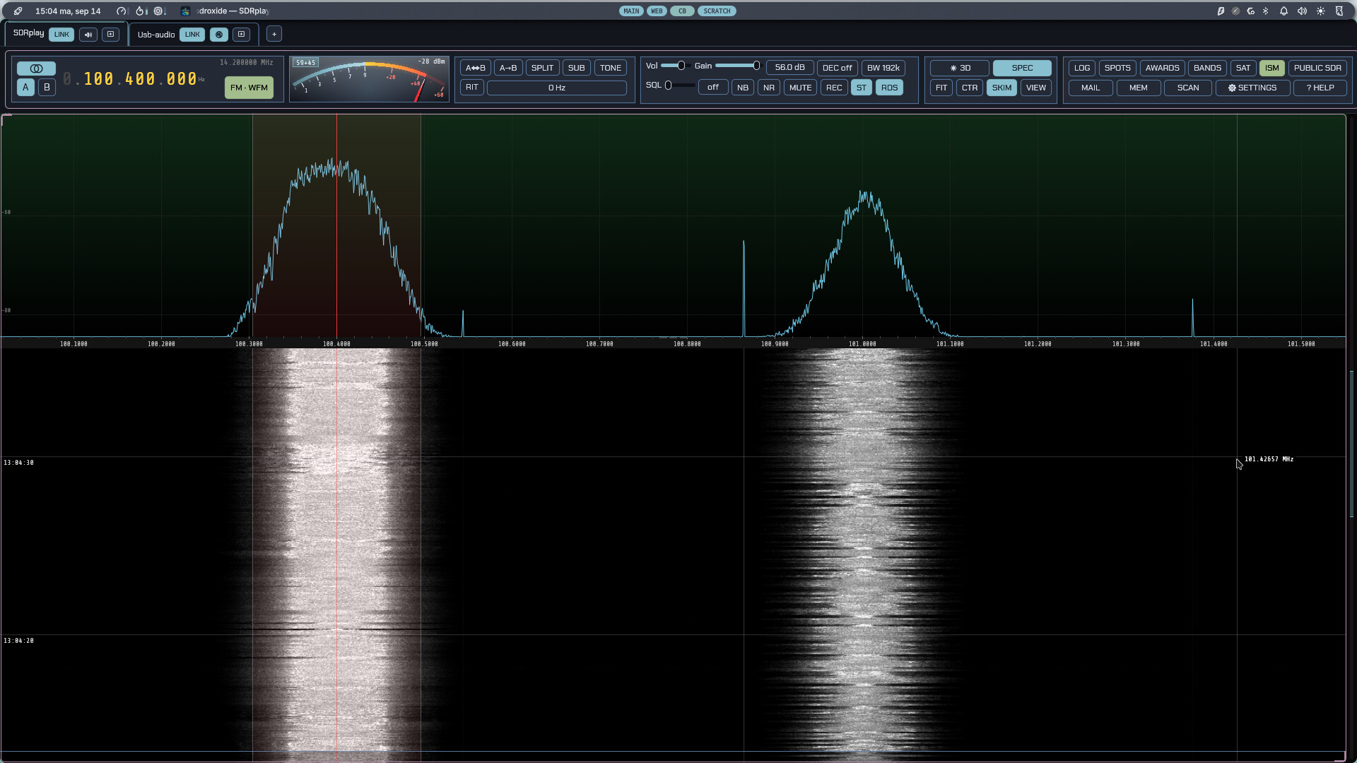
- Panadapter and waterfall with click/drag tuning, scroll-to-zoom, a draggable filter passband, a colour-coded band-plan strip, and eight selectable waterfall colour schemes (including an Icom-style palette).
- Dual VFO (A/B) with split operation, VFO swap/copy, and an independently tunable sub-receiver with its own mode and filter.
- All the common modes: LSB, USB, CW, AM, SAM, C-QUAM, NFM, WFM, DRM, HD Radio, DIGU, DIGL, DSB, ISB (independent sideband — two services on one carrier, one in each ear), a spectrum-only mode (SPEC), the automatic digital modes FT8, FT4 and FT2, the keyboard modes PSK31, RTTY, SYNOP/SHIP, Olivia, THOR and FSQ, the image modes SSTV, weather fax and RIFP (draft-dulaunoy-rifp-00, a packetised image protocol on its own FSK modem), the transmit-only RF Paint (spectrum-painting) mode, AX.25 packet on HF and VHF, and APRS — with a live map of every station heard, drawn with its own symbol, and messages you can send and answer. ADS-B decodes the aircraft overhead on 1090 MHz onto a radar display — see §3.13 — and AIS does the same for the ships on 162 MHz, onto a marine chart with the vessels drawn as hulls pointed the way they are heading (§3.16). HFDL reaches the aircraft that no VHF receiver can — the shortwave ground network airliners use over the oceans and the poles, one assigned channel at a time, with a decode log and a map of the positions it carries (§3.19). AtCHAT NET is a multi-station keyboard and file mode with dynamic master election, a shared roster, and block-CRC-ARQ file/image transfer alongside the chat (§3.17). HFDL decodes the HF aircraft datalink — ground stations across the shortwave band talking to aircraft over the ocean — into a decode log with an aircraft map (§3.19).
- Receive controls: AGC (Off/Slow/Med/Fast), volume, mute, squelch, an impulse noise blanker, an adaptive auto-notch (constant-tone canceller), noise reduction (five engines, three strengths each), front-end decimation (trade span for resolution, processing gain and CPU on any IQ radio), RIT, and a draggable filter passband. On NFM, the CTCSS tone or DCS stream under the signal is decoded and shown, and can be made a condition of the squelch. On WFM, broadcast stereo and RDS/RBDS are decoded automatically — the station name, programme type, radio text, what is playing, and the station’s clock.
- Transmit (on TX-capable rigs): PTT, TUNE, drive and tune-drive levels, mic gain, XIT, and a transmit meter (the rig’s ALC over power output, or over SWR where the rig has no power meter). A ham-band-only transmit lockout is on by default — on digital modes it vets the emission, dial plus offset, not just the dial — as is an SWR guard that stops the over and latches transmit out when the rig reports a bad match — with a looser limit and a five-second grace while you are tuning an ATU. While transmitting, the panadapter shows a monitor of your own signal: wideband IQ rigs display it at its on-air frequency in the full span; CAT rigs and digital modes show a narrow transmit-sideband scope (an approximation built from the outgoing audio).
- CW decode and keyboard sending — a Morse decoder that finds the speed, the threshold and the spacing for itself rather than being told them, with a waterfall cursor that picks the signal to copy (and the frequency to answer on), and a type-ahead keyboard that sends as you type. The same decoder drives the wideband CW skimmer.
- Repeater operation — a transmit shift (manual, or taken from the band plan as you tune), a CTCSS tone or DCS code sent under the voice, and the 1750 Hz burst that opens a carrier-access repeater — from a button, or at the start of every over. A memory stores the whole set-up with the channel.
- Voice keyer — ten recorded messages, transmitted from a button, a numpad
key, a MIDI pad or a Hamlib
send_voice_memcommand; works in the voice modes and in RADE digital voice. - QSO recorder — one button records both sides of the contact to an MP3: what you hear as the receiver delivered it, before the volume control, and what you send as it goes to the transmitter. Split into an ear each where a second receiver or a stereo broadcast is using both channels, centred where nothing is.
- FT8 / FT4 / FT2 with a live decode list, automatic QSO sequencing, a world map, a transcript, and automatic logging.
- Integrated logbook for digital and manual QSOs, with contest and QSL fields, a worked-before check, ADIF import/export and text export.
- Live spotting — a DX cluster (telnet) plus POTA, SOTA, PSK Reporter and FreeDV Reporter feeds shown as clickable markers on the panadapter and world map; click to tune and pre-fill a log entry.
- FreeDV Reporter — report your station to qso.freedv.org and see who else is on FreeDV, including callsign exchange in the RADE End-of-Over frame.
- Callsign lookup and QSL upload — QRZ/HamQTH name/QTH/grid auto-fill, and one-click (or automatic) upload to eQSL, QRZ Logbook, HamQTH, Club Log, World Radio League and the 11 m LOG11DX logbook, with LoTW ADIF export and confirmation download. Each service’s credentials can be tested against it from the settings, without logging anything.
- Award tracking — live DXCC / WAS / WAZ / grid tallies, worked vs confirmed.
- Winlink radio email — a native client for the amateur store-and-forward email network: B2F/FBB forwarding, LZHUF compression and the secure login, with a mailbox, compose and reply, and attachments (§11).
- Wideband skimmers — a CW skimmer plus PSK31 and RTTY skimmers that decode many signals at once and label them on the waterfall.
- ISM band decoder — reads the unattended 868 MHz traffic around you and lists each device with its readings in real units. See ISM band decoder.
- Zoom out past the I/Q — on a receiver that publishes a full-band spectrum as well as its I/Q (a KiwiSDR, a SpyServer, an RX-888), the main panadapter keeps widening past the streamed passband and draws those spans from the full-band bins. See §2.8.
- QO-100 beacon plugin — tracks the 10489.750 MHz narrowband beacon, measures how far your LNB is off, and (with AUTO) keeps correcting the converter offset as it drifts. In the SAT window’s QO-100 tab; see §2.22.
- Many radio backends: SoapySDR devices, OpenHPSDR (Hermes/Metis) Ethernet
SDRs, a TCI server (ExpertSDR3/Thetis), a SmartSDR radio (FlexRadio
FLEX-6000/8000), RTL-SDR, RX-888, Airspy HF+ and SDRplay RSP receivers over
USB, an Airspy R2 or Mini over USB, a HydraSDR RFOne over USB, a RigExpert
Fobos SDR over USB, a HackRF
transceiver over USB, an RTL-SDR
published over the network by
rtl_tcp, a PlutoSDR, or a CAT-controlled radio with audio over a USB sound card (demodulated audio or stereo IQ) — plus a USB audio radio: a handheld or walkie with no control port at all, reachable only through the sound card, keyed by its own VOX (§15.22). A DIY isolated FTDI + optocoupler interface puts a commanded PTT on such a radio too, e.g. the Luiton LT-310SDR (§15.23, experimental). - Several radios at once — each in its own tab with its own tuning, mode, panadapter and audio, sharing your memories, logbook and a station-wide transmit interlock. Multi-receiver hardware serves one tab per receiver from a single connection: a TCI rig’s RX2, an HPSDR Protocol 2 board’s DDCs, a 2R2T PlutoSDR’s second chain.
- One radio as another’s panadapter — give a CAT transceiver a real wideband display by lending it an SDR’s receiver, on the shared antenna or from the rig’s I.F. output (with a per-mode offset for a rig whose I.F. moves with the mode). The dial, mode and transmitter stay with the transceiver, and you listen to whichever of the two you choose.
- Memory channels and per-band memory of your last frequency/mode/filter.
- Solar system 3D view — the Sun, the Earth and the Moon, the other seven planets and eighteen of their moons with their orbits, live NASA SDO solar imagery, sunspot regions and CME trajectory cones, an arrival estimate when one is headed our way, the live auroral oval standing over the globe with a Kp forecast for tonight, live amateur-satellite orbits with click-through pass predictions, your FT8 contacts arcing between stations, a propagation panel with MUF, Kp/A, F10.7 and the current GOES X-ray level, and a bar chart of how open each band is right now.
- Spoken announcements: the radio reads itself out — frequency, mode, band, split, AGC, the transmit levels, band-edge warnings, the SWR while you tune up, and FT8/JS8 messages addressed to you — so it can be operated without seeing it. The voice ships with the program and runs on your own machine. The window is also exposed to NVDA, Orca and VoiceOver. See 6.3.
- Remote and web operation: run headless as a server and control it from a browser or from a second sdroxide instance over the network, behind a username and password. A station reached that way opens as a radio tab beside your own ones — enter its address on Settings → General and press CONNECT.
2. Basic operation
2.1 Launching
Start the native application with no arguments to use your configured radio:
sdroxide
To try the interface with no hardware, use the built-in signal generator:
sdroxide --siggen
See the command-line reference for all options.
2.2 The main window
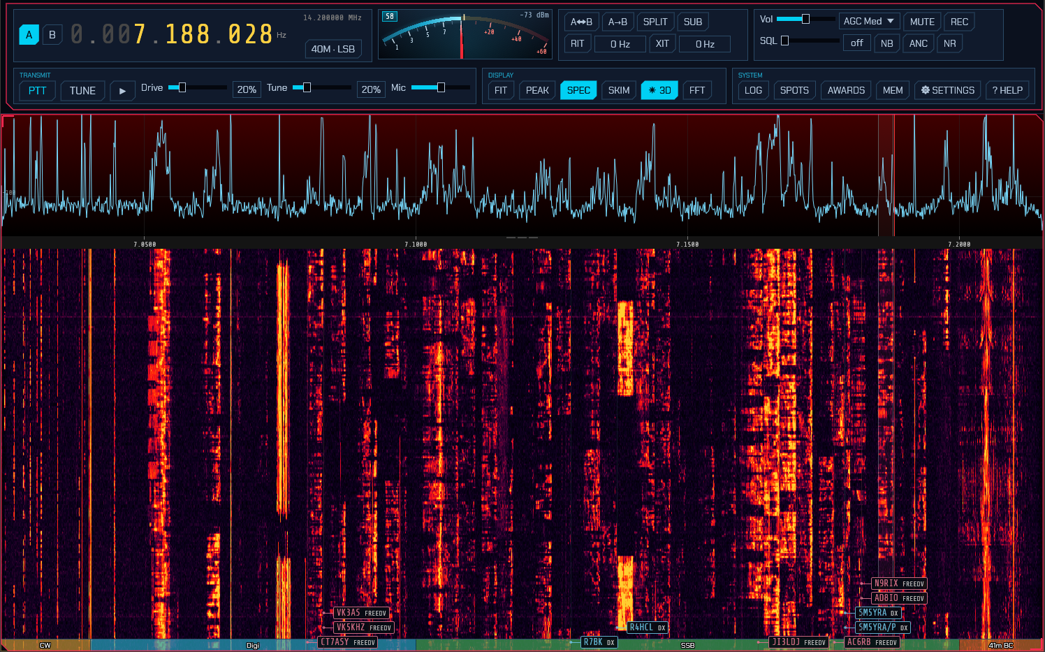
The window has two parts: a top control bar of captioned modules that reflow onto more rows as the window narrows, and the panadapter (spectrum plus waterfall) filling the rest of the window. In FT8/FT4/FT2 the lower part of the window is shared with the digital operating panel.

The control-bar modules, left to right, are: Frequency, S-meter, Band/Mode, VFO, RIT/XIT, Receiver + Filter/Noise, Rig (only on a radio with an aerial selector or a remote power switch), Transmit (TX-capable rigs only), Display, FFT, and System.
Copying a tooltip. Almost every control explains itself in a tooltip when the pointer rests on it. The text of a tooltip cannot be selected, so while one is on screen press Ctrl+C (⌘C on a Mac): its whole text goes to the clipboard, ready to paste into a translator, and a short Copied note appears by the pointer. With no tooltip on screen Ctrl+C does what it always does. This works in the desktop program and in the browser (the browser needs the page served over https to reach the clipboard); a phone has no Ctrl+C.
2.3 Tuning
The frequency readout is a ten-digit display. Hover over any digit and:
- Scroll the mouse wheel to tune that decade up or down.
- Click the upper half of a digit to increment it, the lower half to decrement it.
The smaller grey number below the readout is the inactive VFO’s frequency.
On the panadapter:
- Scroll the wheel to zoom in and out around the cursor.
- Press F to reset the view to the full receiver span.
- Left-click tunes the active VFO to the clicked frequency. Shift+click places the second receiver: the sub-receiver when SUB is on, VFO B otherwise. Unlike a plain click, it means the same thing everywhere — over a spot box it takes the spot’s frequency, and in FT8/FT4/FT2 it still tunes rather than moving the transmit offset.
- Left-drag grabs the spectrum and slides it (the tuning moves with the content). Drag past the end of the span the receiver is capturing — which, zoomed all the way out, is from the first pixel — and the receiver itself follows: the window slides across the band under your hand instead of stopping at its own edge, so on a wideband receiver such as the RX-888, where retuning costs nothing, you can drag from one end of HF to the other. The picture stops where the front end runs out of range. A rig whose I/Q output is its own dial (a transceiver on a sound card, an Icom sending its 12 kHz IF) has one synthesiser for both, so there the drag moves the window by moving the dial, as it always has. Let go while the pointer is still moving and the dial keeps turning, coasting to a stop like a weighted VFO knob — the faster the flick, the further it runs. A slow, careful drag lands exactly where you release it, and pressing anywhere on the panadapter catches a coasting dial and stops it dead (that press does not tune). The sub-receiver’s tuning drag has the same flywheel.
- Right-drag pans the view only, without changing tuning — and only inside the captured span, since moving the window means moving the receiver.
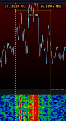
- Shift+drag measures bandwidth: a horizontal ruler with dotted vertical markers appears between where you pressed and the current pointer, showing the start and end frequencies at the markers and the frequency span (e.g. a signal’s width) below. It works on both the spectrum and the waterfall. When you release the button the measurement lingers and fades out over about five seconds, so you can read it after letting go. The same ruler works on the full-band strip (see WIDE in §2.8), where it measures in megahertz.
Keyboard tuning (ignored while typing in a text field):
- Left / Right arrow: ±100 Hz (with Shift, ±10 Hz).
- Up / Down arrow: ±1 kHz.
- Page Up / Page Down: ±10 kHz.
Each of these lands on a multiple of its own step, so a dial left on an odd frequency by a drag is put back on a round one by the next key press. Wheel tuning does the same, and one notch of the wheel is one step of it.
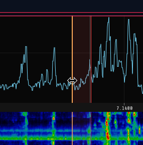
Band-plan strip. A colour-coded strip along the bottom of the waterfall (its top when the waterfall is flipped — see §2.8) labels the allocations. Zoomed out it shows coarse bands (ham, broadcast, CB, AM); zoomed into a ham band it splits into the CW / digital / SSB / beacon sub-segments, or an all-modes block where the plan gives one. When you zoom in close (a span of ~100 kHz or less), the digital sub-band is broken out into the individual popular modes — FT8, FT4, FT2, JS8, WSPR, QRSS, PSK, RTTY, SSTV, RIFP, FREEDV — each in its own colour.
Everything on the strip follows the IARU region on the General tab (6.1) — the ham blocks, their sub-segments, and the shortwave broadcast blocks that overlap an amateur band in one region and not another (3.900–4.000 and 7.200–7.300 are broadcasting in Regions 1 and 3 and amateur in Region 2).
Memory marks. Every stored memory whose frequency falls on the visible span
is labelled just inside the band-plan strip, reading Mem: folder / name — or
Mem: name for one that is not filed in a folder — on a thin green line drawn
at the frequency itself. Channels close together stagger into stacked rows
rather than overprinting; a name too long for its label is cut short with an
ellipsis, and anything that would need a fifth row is left out.
Click a mark to recall that memory — dial, mode and filter together, exactly as pressing it in the memory list does; the label brightens as you point at it. Shift-click one to put the second receiver on its frequency instead, as shift-clicking anywhere else on the panadapter does. §2.12 is where a channel is stored, renamed and filed.
2.4 Bands and modes
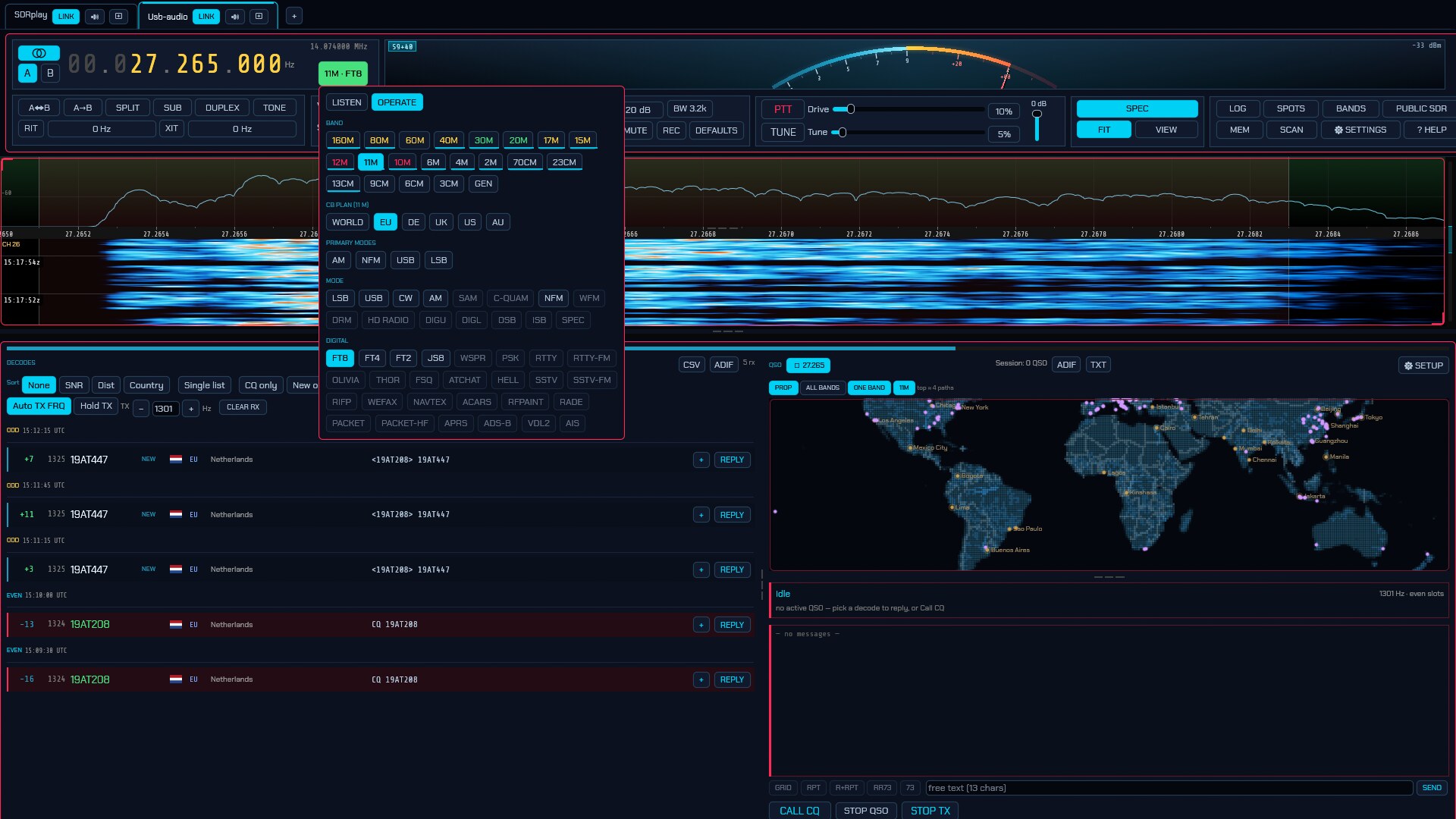
Click the Band / Mode button (which reads, for example, 20M · USB) to open
the band/mode popup. One list of every band and mode had grown past a screenful,
so it is split into two halves, chosen by the LISTEN and OPERATE tabs at
its top:
- LISTEN — the broadcast and utility bands, the metre bands, and every receive and digital mode. Nothing here is greyed for the band: a listener may want to try a decoder where the table would not put it, so the LISTEN tab offers every mode on every band.
- OPERATE — the amateur allocations, the CB plan, and the primary, analog and digital modes, with the band/mode rule enforced.
The band row of both tabs leads with HF · VHF · UHF · ALL. HF, VHF and UHF narrow which band buttons are shown — HF is everything below 30 MHz (longwave and medium wave included), VHF 30–300 MHz, UHF above that — and the lit chip toggles itself back to all. ALL is general coverage: it clears the band so the dial can go anywhere. The filter only hides buttons and never moves the dial.
On a desktop layout the popup’s DOCK chip keeps the selector open as a resizable column beside the waterfall rather than a popup that closes on the next click — handy while working a band plan or a set of channels. In the column, UNDOCK returns it to the popup and × hides it until the top-bar band chip brings it back; while docked, that chip toggles the column. Docking is offered on the desktop layouts alone: a window narrow enough to be a phone undocks and keeps the popup.
In the OPERATE tab a pair that cannot work is not offered: a mode that
does not apply on the current band is greyed, with the reason on hover. FM
broadcast is WFM alone, both airbands are AM, and 11 m is AM, NFM, SSB, CW and
the WSJT-CB digital exchange — so AM is dead on the FM broadcast band and
WFM is dead on 11 m. The engine refuses the same pair if a remote client
sends it directly. The amateur allocations and general coverage take any mode;
there, a band plan’s own segments are the only thing narrowing the choice.
Selecting a band is never blocked this way — it is how you leave a service
mode — and the band you pick adopts a mode that fits it, as the FM broadcast
band has always come up WFM. The LISTEN tab is deliberately exempt from the
rule: it offers every mode on every band, and the mode change goes through a
command that skips the band check, because exploring is what that screen is
for. Transmit legality is untouched — the band lockout and the TX rails still
decide what may be keyed, and a mode that cannot transmit simply does not.
The OPERATE tab’s rows:
-
BAND:
LW MW 160M 80M 60M 40M 30M 20M 17M 15M 12M 10M 11M 6M 4M FM 2M 1.25M 70CM
33CM 23CM 13CM 9CM 6CM SW
. (ALL, the general-coverage entry, is not in this run — it rides with the HF/VHF/UHF chips above.) Each band remembers your last frequency, mode, and filter. A band your region’s band plan does not have gets no button at all —4M(70 MHz) is an amateur allocation in IARU Region 1 only, so it is absent in Regions 2 and 3, and1.25M(220 MHz) and33CM(902 MHz) are Region 2’s alone, so they are absent in the other two.6CMreads5CMoutside Region 1, which is what the band plans there call it.11Mis the citizens’ band — a two-way band, used to the full here, with its own service rules rather than an amateur allocation. The generic ham lockout holds until the station opts in once with Allow transmit on 11 m (CB) (6.1).LW,MW,SWandFMare the broadcast services a short-wave listener tunes: longwave 148.5–283.5 kHz, medium wave 526.5–1606.5 kHz (530– 1700 in the Americas), the whole shortwave broadcast span 2.3–26.1 MHz, and VHF FM broadcast 87.5–108 MHz. None is an amateur allocation, so the same lockout applies, and each stays an ordinary band button: the dial jumps there (198 kHz AM, 1 MHz AM, 6.175 MHz AM, 100 MHz WFM), band stepping walks through them, and the band stack remembers what you last listened to. Picking a band always comes up in a mode that fits it: the broadcast FM band is WFM whatever the stack last held — an FM broadcast channel is nothing to listen to in AM — and any band whose stored mode no longer applies falls back to its own default the same way.SWdeliberately overlies the amateur HF bands, and the amateur band always wins the name — a frequency in a shared span reports as the amateur band,SWowns only the broadcast-only slice (6.1); the labels that make these bands usable are in §10.6. Tick SWL mode on the UI tab (6.3) and every transmit control disappears, for a clean receive-only radio. Once band conditions have been fetched the button are tinted by the published forecast — green Good, yellow Fair, pink Poor — and hovering one gives it in words. Bands the forecast does not cover (the broadcast bands among them) are left uncoloured; see §2.15. In a digital mode, the bands where that mode has a standard calling frequency carry a cyan underline; see §3.1. - CB PLAN (11 M):
WORLD EU DE UK US AU— which country’s channels the 11 m dial reads in. 11 m is not one band: the world shares the 40-channel CEPT/FCC table (EU), Germany adds a high band for 80 (DE), the UK’s 27/81 channels sit at their own frequencies (UK), and the US and Australia work the shared 40 in AM and SSB.WORLDis the permissive default — the 40 shared channels plus the high band, any mode. The plan decides the channels, the channel the band opens on, and theCH nnreadout on the panadapter; it does not move the band’s edges, so switching never changes what receives or transmits. The same choice is on the General tab (6.1). - MODE:
AM NFM USB LSBfirst — the four a CB or short-wave operator reaches for — then a divider and the rest:CW SAM C-QUAM WFM DRM HD DIGU DIGL DSB ISB SPEC.FMhere is NFM (narrow); the broadcast band’s own button comes up WFM (see below). - DIGITAL MODES: a dropdown that shows the mode in force when a digital one
is chosen, otherwise reads Digital modes. It opens onto the full list —
FT8 FT4 FT2 JT65 JT9 FST4 MSK144 FSK441 Q65 UVPACKET JTTY JS8 WSPR PSK RTTY
RTTY-FM OLIVIA THOR FSQ ATCHAT HELL SSTV SSTV-FM NAVTEX DSC RIFP RFPAINT RADE
PACKET PACKET-HF APRS
and a Wideband groupADS-B VDL2 AIS HFDL DAB(see Digital modes). A dropdown rather than three dozen chips on the face: a mode is picked once, but it has to be visible as a choice.
On a desktop or tablet layout the popup carries a DOCK chip. It moves the selector into a resizable column beside the waterfall so it stays open while you tune, instead of closing after every choice. UNDOCK in the column’s header returns it to the popup, and × hides the column — the Band / Mode button then shows and hides it. The column is 180 to 320 points wide and always leaves the waterfall at least 600, so docking needs a window of about 780 points or more, and never happens on a phone layout. In a narrower window the column is hidden and the Band / Mode button opens the popup again; widen the window and the column comes back.
See the appendix for what each mode is.
2.5 VFOs, split, and the sub-receiver
The VFO module has:
- A / B select buttons in the Frequency module (the active VFO is highlighted).
- Above them, the ⛓ link button: the same LINK switch the radio’s tab on the strip carries (see §2.17), lit while sdroxide’s link to the radio is open. It is on the main window so that a single-radio session — which has no tab strip — can still put its radio down and pick it back up. On the compact layouts, where the frequency box has no room to stack it, it is the first thing in the VFO menu instead, labelled in words. It is not the radio’s power switch: that is PWR (§2.7).
- Swap VFOs — exchange A and B.
- Copy A to B — copy the active VFO to the other.
- SPLIT — transmit on one VFO and receive on the other.
- SUB — enable a second receiver, routed to the right ear.
Each VFO keeps its own mode, its own filter width, and its own antenna. A VFO is a whole listening position rather than just a number — CW on A while B sits on an SSB net is what the pair is for — so switching between them puts the receiver into the mode that VFO was left in and back on the socket it was heard on, exactly as the A/B button on a transceiver does. Swap and Copy A to B move all of it along with the frequency: after a swap each VFO holds what the other one had, and after a copy B is A in every respect.
The antenna is remembered per band as well (6.2), and the two memories divide the work by what you have just done. An A/B press that stays inside one band keeps each VFO’s socket — Antenna A on a broadcast station and Antenna B on the amateur allocation below it is one band and two sockets, which the band memory alone cannot express. Crossing a band edge recalls the band’s socket instead, whether you got there by the dial or by pressing A/B onto a VFO parked on another band: which aerial hears 2 m is a fact about the station rather than about a VFO. Choosing a socket by hand is what writes the band’s entry, so the band always holds your last explicit choice on it.
Both VFOs, the mode and socket each was left in, and which of the two was
selected are remembered per radio in session.json, so a station left listening
on B — or set up for split, with the other VFO on the DX’s transmit frequency —
comes back the same way at the next start rather than with B collapsed onto A.
--freq and --mode still override the dial and the mode for a run, and they
apply to whichever VFO was active.
The sub-receiver tunes independently of A/B: swapping VFOs or turning the dial leaves it where you parked it. Switching it on reveals a SUB module in the top bar with everything it has of its own:
- Frequency — type it in MHz, or drag the field to tune in 10 Hz steps.
- ←DIAL / DIAL← — send the sub to the main dial, or bring the main dial to whatever the sub has found.
- Mode and Filter — the sub demodulates independently of the main receiver, so you can listen to CW on one and SSB on the other. (Audio modes only: the digital modes decode on the main receiver.)
- Vol / MUTE — the sub’s own level in the right ear.
On the panadapter the sub is drawn in violet, with the same passband wash,
draggable filter edges and tuning line the main receiver has, labelled SUB.
Drag inside its passband (or on its tuning line) to tune it — that drag moves
the sub instead of panning the view, so each receiver is tuned by dragging its
own filter area. Released mid-motion it coasts on like the main dial, stopping at
the edge of the receiver’s span. Shift+click anywhere sends the sub straight
there.
Both receivers are tuned by DDCs on the same IQ stream, so the sub can reach anything inside the receiver’s span and nothing outside it. A band change that moves the hardware out from under the sub re-parks it on the inactive VFO.
2.6 RIT and XIT
The RIT / XIT module offsets receive (RIT) and, on TX-capable rigs, transmit (XIT) without moving the dial. Toggle RIT (or XIT) on, then set the offset in the adjacent field (±9999 Hz in 5 Hz steps).
When either is enabled, the offset is drawn on the panadapter: RIT shows a dashed grey dial reference line (the receive marker and passband already sit at dial + RIT) with a blue labelled bracket back to the dial, and XIT shows a green TX marker line with a green labelled bracket from the transmit base to dial + XIT — so you can see at a glance how far RX and TX are shifted.
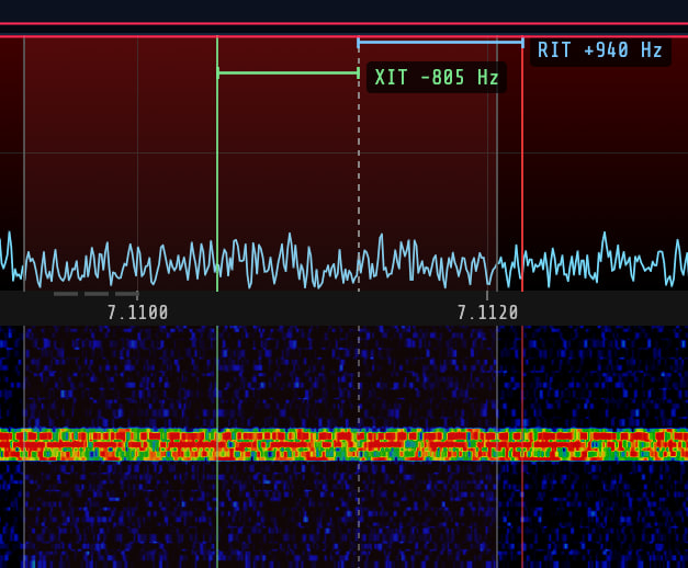
On an SDR, all three offsets — RIT, XIT and split — are software: the receiver and transmitter are tuned inside the IQ stream and the hardware never moves. A CAT radio has no such stream, only its dial, so sdroxide puts them on the dial instead: it sits on your receive frequency (VFO + RIT) while you listen and moves to the transmit frequency (the other VFO when split is on, plus XIT) for the length of each over, then comes straight back. The radio’s frequency display follows, which is also how you can see it working. sdroxide switches the radio’s own RIT, XIT and split off when it connects, so an offset left over on the rig can’t quietly add itself to the one you set here.
The same box carries the DUPLEX and TONE buttons — the fourth thing that moves the transmit frequency, and what has to ride under it. See 2.18 Repeater operation.
2.7 Receiver controls
The receiver and its filter/noise controls share one box of two rows. Which row a button lands on is not fixed: the top row carries the level controls the radio offers — the volume, a front-end gain rail where there is a gain to set, decimation where there is a span to throw away, the AGC where the mode has one — and on a rig with few of those, the buttons from the row below move up to fill it rather than leave half the box empty and the box itself twice as wide as the strip can afford. So the same button can sit on the top row on a CAT rig and on the bottom row on an SDR with a gain slider, and it moves when you change mode. What is in the box never changes; only where the two rows are cut does.
-
AGC — a drop-down:
Off,Slow,Med,Fast. Not shown in NFM, WFM or DRM, where there is no AGC at all: an FM detector’s output level is set by the transmitter’s deviation, not by signal strength, and a DRM decoder hands you the audio at the level the broadcaster mixed it to, so in both there is nothing to level and an AGC would only pump on the noise between overs.It is a listening control and nothing else. The decoders are fed from a tap taken ahead of it, on a level that takes seconds to move and so cannot change inside a transmission — which is what a modem needs and what an AGC, attacking in two milliseconds, is the opposite of. So whatever you set here, FT8 sees the same signal.
- Man — the fixed audio gain the receiver runs on while the AGC is
Off, shown only then. Unlevelled audio is whatever the band delivered, and a weak SSB signal can sit tens of dB below anything the volume control can reach, so “AGC off” means this gain rather than no gain at all. Switching the AGC off seeds it from the level the AGC was holding at that moment, so nothing jumps; from there it is yours to set, and it stays put however the signal moves. - Vol — audio volume.
-
DEC — front-end decimation: keep the middle
1/Nof the span the radio streams and throw the rest away, before any of it reaches the receiver. Click to cycleoff / 2 / 4 / 8 …; the button reads what is running (DEC /8), and hovering it tells you the span you are left with.It shows on any radio that delivers IQ and has bandwidth to spare, and applies to all of them equally — a dongle at 2.4 Msps, a HackRF at 2 Msps, an RSP, a Pluto. A radio already streaming a narrow span (an HPSDR at 48 kHz, say) offers no button, because there would be nothing left to decimate to. The floor is 48 kHz: that is one receiver channel, and below it the waterfall stops being a band display.
What you gain:
- Resolution, everywhere at once. The same FFT spread over an eighth of the bandwidth is eight times finer, across the whole span rather than only the part you have zoomed into. (Zooming gets its own resolution without this — see the FFT control in §2.8 — so this is no longer the only way to a detailed picture, but it is still the way to a detailed picture of everything you can see.)
- A quieter noise floor. Every halving throws away half the noise power
with half the bandwidth: 3 dB per step, 9 dB at
/8. The signal you are listening to is unchanged, so this is real processing gain, and weak signals stand further out of the grass. - CPU. Everything downstream — the FFT, both receivers’ downconverters, the skimmers, the IQ a TCI client is being fed — runs at the reduced rate. On a small machine this is the difference between a 2.4 Msps dongle being comfortable and not.
What you give up is the band either side of the kept span. The dial still tunes anywhere: as you tune past the edge the radio simply moves its LO and the narrower window follows you. Nothing is reconfigured in the hardware — the radio keeps streaming exactly as it was — so the setting takes effect on the next block of samples, with no gap in the audio and no risk of a device refusing it. The sub receiver still has to live inside the span, so if it was parked outside the new one it is moved back in.
- BW — the receive filter as a number. The chip reads the passband width
the receiver is running (
BW 2.7k,BW 500), and clicking it opens the width, the two edges and the mode’s standard filters as fields you can type into. The panadapter’s grips are the quick way to place a passband by eye against what is on the band; this is where an exact figure — 2200, 2700, 3000 — is entered, which a drag can only creep up on (issue #371). See 2.7 for what the numbers mean in each mode. In WFM it sets the channel filter in front of the FM detector — narrow it to keep a strong station 100 kHz away out of a weak one, at the cost of stereo and RDS first and audio distortion after; it will not go below 20 kHz (issue #414). - MUTE — mute the receiver (keyboard shortcut M).
- REC — record what you hear and what you send, or the raw spectrum to an MP3 file, and choose whether it is written in two channels or one. See 2.21.
-
SQL — squelch; below the open threshold it reads
off.On a radio that hands sdroxide audio it has already squelched — a CAT rig on a sound card, an Icom sending AF over the network — this rail sets the radio’s own squelch over the control link instead, and reads as a percentage of the radio’s scale (
openat the bottom). That is the gate the audio actually passes through: a threshold applied on this side could only close further on what the radio already let by, and could never open up a weak station the radio had muted. The level is read from the rig when the control link opens, so the rail starts where you left the knob rather than imposing a remembered figure on it, and a keyboard or MIDI binding on the squelch action follows the same rail. Every other front end — anything sending sdroxide I/Q — keeps the dBFS threshold, which is the honest one there: the whole passband arrives and sdroxide does the gating.The dBFS rail runs from fully open up to full scale, and hovering it says what the passband is reading now so you can put the threshold between the noise and the signal instead of hunting for it. That number is not the S‑meter’s: the meter has the front end’s gain taken out and your calibration offset put in, and on a rig that reports its own meter it is the rig’s reading rather than a measurement made here. It matters most on a stream that arrives with the radio’s AGC already in it — an Icom’s 12 kHz IF over the network is a levelled IF, so its noise sits far higher on this scale than an SDR’s raw baseband, above where the rail used to stop, and the gate would not close at any setting you could ask for (issue #394).
- NB — impulse noise blanker on the raw signal (keyboard shortcut N).
- ANC — automatic notch: an adaptive filter that cancels constant tone elements — heterodynes, carriers, and tuner-uppers — while leaving voice and noise. Toggle it on when a steady whistle is spoiling a voice signal. (Like NR, it affects only what you hear, not the digital decoders; leave it off for CW and data modes, whose signals are tones.) It is not offered in AM, SAM, WFM or DRM: on broadcast audio the sustained notes of the programme are exactly what it cancels, so it took the station away with the whistle (issue #434).
- NR — noise reduction on the audio, with five selectable engines. The button
always reads just
NRand lights when noise reduction is in circuit — that is all it tells you, and it never changes width under the buttons beside it. Click it for a picker with an Engine row and a Strength row, which is where you both read back what is running and change it, so any setting is two clicks away; hovering the button names it too. A keyboard or MIDI binding cycles the strength within whichever engine is selected — Off → Low → Med → High → Off — and never changes the engine underneath you.- RNN — a neural RNNoise denoiser. Trained on speech, it recognises the voice and mutes everything else, so it clears non-stationary junk that spectral NR can’t — babble, wind, keyboard/shack noise, fluttering hiss — with little of the underwater warble. Cheap, and the safe default. The three strengths are a wet/dry depth: High is the full effect, Low a lighter touch.
- DFNR — DeepFilterNet3, the strongest of the five. It adds a learned complex filter over the low bins on top of a band gain, so it recovers speech the others have already given up on. It also costs the most CPU by a wide margin, and the model is loaded the first time you select it — expect a short break in the audio at that moment. The strengths are the most attenuation it may apply: 6, 12 and 24 dB.
- SPEC — a Rust port of libspecbleach’s adaptive denoiser. Spectral, but with a psychoacoustic model deciding where suppression would be audible, and a whitened noise floor: rather than carving the residue into birdies it flattens what is left into even hiss. Good on steady static where the neural engines sound processed.
- NR2 — a Rust port of WDSP’s NR2 (
emnr.c), the noise reduction behind the NR2 button in PowerSDR and Thetis, and the one a great many operators already have an ear for. Ephraim-Malah suppression driven by a minimum-statistics noise estimate, with WDSP’s artefact filter smoothing the mask across frequency so hard settings do not ring into birdies. It runs at WDSP’s own settings; the three strengths are a layer on top, telling the gain rule there is progressively more noise than there is and limiting how far any one bin may be pulled down. Roughly 11, 17 and 23 dB off a broadband noise floor. It uses a longer analysis window than the others, so it adds a little more delay — about 32 ms at 48 kHz. - NR — the built-in spectral noise reduction, whose engine button keeps the bare name the button has always worn: it suppresses the stationary noise floor while letting the changing, speech-like parts through. Fast and predictable on steady static and hiss.
All five make voice quieter to listen to and easier to copy with less fatigue. Higher strengths remove more noise but can add faint artefacts on weak signals, so pick the lowest that cleans the audio; on a noisy voice signal, start with DFNR Med, and drop to RNN Med if the machine is struggling. (NR affects only what you hear; the FT8/FT4/FT2/PSK/RTTY decoders still receive the untouched signal, and a steady unmodulated carrier — a heterodyne — is treated as noise and suppressed. Any NR engine also forces WFM to mono — see ST below.)
-
BIN (CW and SSB) — binaural audio: the receive passband spread across the two ears, so that a signal’s pitch becomes a direction. Whatever sits at the middle of the filter is in the middle of your head, anything above it moves to the right, anything below it to the left, and tuning a station floats it across from one ear to the other. Wear headphones: most of the effect is the difference in arrival time between your two ears, which a pair of speakers largely throws away.
In CW that separates a pile-up into several places you can attend to one at a time, instead of one crowded note. In SSB a voice fills the passband rather than sitting at a point in it, so stations do not separate that way — but the noise still spreads across the image while the station stays in the middle of it, which makes a long listen on a noisy band less tiring. The cost is that the voice itself is spread out, low notes towards one ear and sibilance towards the other; try it on a long session and see whether you like it.
The image follows the filter, not the mode, so narrowing the passband spreads the same left-to-right image across less of the band — and the same note lands in a different ear in CW and in SSB, because the middle of a 500 Hz CW filter and the middle of a 2.7 kHz voice filter are not the same frequency. Nothing downstream can tell it is on: the decoders read the audio before this stage, recordings are written from the same tap, and a remote client is sent the mono downmix, which binaural leaves untouched.
The button greys out while the sub receiver is running, which claims the right ear for a second receiver — an explicit second signal outranks an effect on the first.
-
ST (WFM only) — broadcast stereo. It lights when the station’s 19 kHz stereo pilot is locked, and needs nothing from you: mono and stereo stations are handled automatically, at the same volume, so there is no jump when one hands over to the other. Click it to force mono.
On a weak station sdroxide blends back toward mono by itself. That is not a compromise — the difference channel is recovered from a 38 kHz subcarrier, high on FM’s noise slope, so it carries roughly 20 dB more hiss than the mono sum. Clean mono beats noisy stereo, and the blend is gradual enough that you will not hear it switch. Forcing mono is still worth doing on a marginal signal you want to listen to for a long time.
-
RDS (WFM only) — the data the station carries beside its audio: what it is called, what it is playing, and what else it wants you to know. The button lights when data is actually arriving, so it answers “does this transmitter carry RDS?” without your opening anything. Click it for the window.
The station name appears in about a second, the radio text in a few more, and the rest as it comes. Decoding runs the whole time you are on WFM, whether or not the window is open, so it is already filled in when you do open it.
What the window shows:
- The name — the eight characters the station calls itself. Some broadcasters abuse this field by scrolling a message through it a word at a time; sdroxide only shows a name it has seen twice running, which stops a fragment of somebody’s advertisement being displayed as the station’s name, but on those stations the name will still change as you watch. That is the station doing it, not the receiver.
- Identity — the programme identification code, a number that is the station’s real name as far as the standard is concerned. In North America it spells out the call letters, and those are shown beside it.
- Programme — one of 32 categories. Which 32 depends on the standard: the same five bits mean Education in Europe and Rock in the United States. See the selector below.
- Radio text — 64 characters the station can put anything in, and usually the artist and title. Where the station tags them properly (RadioText+), they are lifted out and shown on their own line under the name.
- Traffic — whether this station carries traffic announcements at all, and whether one is on the air right now.
- Station clock, and also on — the other frequencies carrying the same programme, which is what a car radio follows when you drive out of range.
RDS or RBDS — the selector at the top. They are the same signal; the difference is which table of programme types to read it against, and whether to spell the identity code out as call letters. Auto decides from the country code the station sends, which most stations outside North America do. Where one does not, auto still guesses the table from the identity code — that guess can be wrong, so set the selector by hand when the programme type reads like nonsense — but it will not name the station from it. The call-letter range overlaps identity codes that are perfectly ordinary elsewhere: a Finnish or Danish station’s identity decodes to a plausible American call sign, and four invented letters sitting where the station’s name goes look like fact in a way a wrong category does not. Select RBDS by hand to name a North American station that sends no country code.
Nothing is re-decoded when you change it: the raw codes are already here, so everything on screen re-labels itself at once.
DIAGNOSTICS, the second tab, is for when the first one is empty or flickering. It shows whether the decoder is in sync, how many groups have arrived, what fraction of blocks failed their check, and a running log of the groups themselves. The block error rate is the number to watch: it counts repaired blocks as errors on purpose, so it starts climbing before anything visibly breaks, and a station sitting at a few per cent is one that will drop out when a lorry goes past. A station sending no group 2A sends no radio text — the group list will tell you that, where the blank field cannot.
FRONT END OVERLOADING — the station is too strong, the converter is clipping, and the distortion lands right across the multiplex including on the 57 kHz subcarrier the data rides. Nothing you can hear will tell you, and that is the point of the warning: the whole distance between clean RDS and none is about a decibel, and across all of it the audio stays clean and the stereo light stays on. Turn the RF gain down or switch in an attenuator. The S-meter shows
OVLfor the same reason (2.9).One thing is deliberately not shown: traffic message channel data is decoded by nobody here. The messages are numeric references into a licensed location database, and without it “event 108 at location 12345” is all there is to say.
- DRM (DRM only) — how the Digital Radio Mondiale decoder is getting on. The button lights only when audio is actually being decoded, not merely when a carrier is present, so it answers “is this station coming through?” at a glance. Click it for the window, which is where to look when the answer is no: it shows how far up the chain the decode got. Full detail is in 2.19.
- HD (HD Radio only) — how the HD Radio (NRSC-5) decoder is getting on. Like the DRM button it lights only when audio is actually being decoded, not merely when the OFDM frame is locked, so it answers “is this station coming through?” at a glance. Click it for the window, which is where to look when the answer is no: it shows how far up the chain the decode got and the error ratios of both digital sidebands. Full detail is in 2.20.
-
Tone (NFM only) — the CTCSS tone or DCS code under the signal. Analog FM systems carry a sub-audible tone below the voice so a receiver can ignore traffic that is not theirs, and the button shows what is arriving:
88.5for a CTCSS tone, orDCSfor a digital coded squelch stream. On an idle or toneless channel it just readsTONE.It takes about a second of signal to appear. That is not slowness for its own sake: the closest pair in the standard table is 67.0 and 69.3 Hz, and telling 2.3 Hz apart takes about a second however it is measured. Expect the tone roughly a second after a repeater keys up, and expect it to stay for about half a second after it drops.
Clicking the button opens the tone squelch picker: choose a tone and the audio only opens when that tone is present, which is how you sit on a busy shared channel and hear one system. USE 88.5 arms whatever is being received right now, which is usually what you want; OFF goes back to plain carrier squelch. While a tone squelch is armed the button turns yellow, and it lights when the required tone actually arrives. Note that the ordinary SQL slider still applies — tone squelch is an extra condition on the same gate, not a replacement.
DCS is reported as
DCSwithout its three-digit code. The code travels in a cyclic error-correcting codeword, so every one of the 23 possible word boundaries decodes to a valid code and picking the wrong one yields a different, equally plausible answer; without a transmitter to check against, a code shown here would be a coin toss between two of them. That the signal is DCS, on the other hand, follows from the data repeating exactly every 23 bits, which needs no such assumption. Arming tone squelch on ANY DCS opens on any DCS-coded signal.The sub-audible tones no longer reach the speaker: NFM audio is high-passed at around 250 Hz, as it is in any FM receiver, so what used to arrive as a low rumble under the voice is now decoded instead of heard.
Two things turn stereo off on purpose: switching on the sub receiver, which claims the right ear for itself, and switching on NR or ANC, which delay the audio in a way the stereo matrix cannot survive. Neither buys anything on a broadcast signal.
The receive filter is set by dragging the passband edges directly on the panadapter: two vertical grip lines mark the filter’s low and high edges (they brighten to orange when you can grab them). Drag an edge to widen or narrow the passband. The grips work on both the spectrum and the waterfall.
For an exact figure, use the BW chip in the receive box instead — it reads
the current width and opens three things: this mode’s presets (2.4k,
2.7k, 500, …), a width field in hertz, and the two edges, each of
them typeable. A drag can only creep up on 2700 Hz; the field is where it is
said. Changing the width keeps the passband where it is rather than moving the
signal inside it: a channel about the carrier grows either side of it, CW and
RTTY grow about the tone they are centred on, and on a sideband the cut nearest
the carrier stays put while the far edge moves — which is what a transceiver’s
own bandwidth control does. The presets are taken as written except in CW,
where they are re-centred on your own sidetone pitch, so a 250 Hz filter is
250 Hz about the note you copy at rather than about somebody else’s 700.
In AM, SAM, DSB, ISB and the FM modes the two edges move together: the passband is a channel carved out about the carrier, both halves carry the same signal, and narrowing one alone would throw away half the audio while letting the interference on the other side straight through. So whichever grip you take sets the half width and the other edge mirrors it — which is also why every filter preset these modes offer is symmetric. In SSB, CW and the data modes the passband sits to one side of the carrier by definition and each edge stays yours to place on its own.
Hold Ctrl (Cmd on a Mac) while you drag and the mirroring is suspended
for that drag: the grip you have hold of moves and the other stays where it is,
even in the modes that normally pair them. That is the answer to a station
splattering on one side of an AM carrier — close the passband on that side and
leave the other open, trading half the audio for none of the interference. The
figure beside the grip tells you which rule is in force: ±3000 Hz while the
edges are paired, -3000 Hz while the one you are holding moves alone.
ISB is the odd one in that list. Its two edges move together like AM’s, but what they set is the width of each sideband rather than of one shared channel — the preset marked 2.7k gives you 2.7 kHz on each side, so 5.4 kHz of spectrum. The two sidebands are separate transmissions and are demodulated separately: the lower goes to your left ear and the upper to your right, the way they sit on the waterfall, and the ST indicator lights to say the two ears really are carrying different things. A residual carrier on the dial is notched out rather than let through as a hum in both. Noise reduction and the auto-notch turn ISB back into mono for as long as they are on, for the same reason they do to WFM stereo: they run on one channel of the pair and the delay would collapse the other into a comb filter. ISB is receive only — transmitting it needs two modulators feeding one linear amplifier, which is a station rather than a setting.
The volume, AGC mode and manual gain, the squelch, the noise reduction and the
decimation are remembered in session.json and restored the next time you
start, along with the front end’s own gain stages
(§6.2.1). They are
settings you arrive at by ear against your own antenna and noise floor, so
sdroxide brings the receiver back up where you left it rather than on defaults.
The RIG box: the radio’s own aerial and power switches
A transceiver with an aerial selector, a separate receiving antenna, or a power switch sdroxide can reach over the control link, gets a RIG box of its own on the control bar — next to the receive controls on a desktop layout, and behind a RIG button in the menu strip on a narrow window. Like DIV and SUB, it appears only for hardware that has what it drives; a radio with one socket, no receive aerial and no remote power never sees it.
- ANT — the socket the radio is receiving on, as a button you click to step
to the next one:
ANT1→ANT2→ANT1on an Icom, and round the ports of an RSPdx or a LimeSDR in the same way. It is the radio’s own setting, the same one as the ANT button on its front panel, and it is remembered per band like every other antenna choice in sdroxide — so this is the control for changing your mind, and the band memory is what saves you from having to. It appears only where there is a choice of sockets: an IC-7300MK2 has one, and shows RX ANT alone. -
RX ANT — the radio’s separate receiving antenna, switched into the receive path or out of it, lit while it is in. Not a choice of socket: it is an extra input — a loop, a beverage, a preamplifier — and the aerial on the main socket stays on transmit throughout. An IC-7300MK2’s RX ANT IN/OUT, an IC-7610’s RX ANT.
Unlike the socket above, sdroxide does not remember this one. The radio holds it per band itself, so sdroxide asks the radio again after every band change and shows what it answers; clicking the chip is the only thing that moves it. The one thing that will not reach the chip is the RX ANT button on the radio’s own front panel pressed without changing band — it catches up at the next band change.
- PWR — ON and OFF switch the radio itself, over the control link. This is the one true on/off in sdroxide; the LINK switch in the tab strip is sdroxide’s own end of the connection and leaves the radio running (2.17). Two buttons rather than a switch, because a radio that is off answers nothing and there is no position to read back.
These are the same controls that live under Settings → Radio (§6.2.2), where the longer explanation of what each one needs from the radio is; they are here so that changing bands and reaching for the other aerial do not mean opening a dialog.
Per-mode settings (the reset chip)
The settings in this box are a matter of taste, but not the same taste in every mode: a little noise reduction helps a weak SSB voice and only gets in the way of an FT8 decoder, and a slow AGC is kinder to a signal sitting in the noise than the fast one that sounds right on a strong local. So each mode carries a set of starting values for AGC, Man, SQL, NR, ANC, BIN, WFM’s ST, and the receive tone and LOUDNESS of the EQ popup, and selecting a mode — here, or on a CAT rig’s own controls — lays its own on the receiver. The tone and LOUDNESS are off in every mode until you switch them on, so ticking LOUDNESS for a broadcast in AM leaves your SSB and FT8 exactly as they were.
The built-in defaults are deliberately plain. A slow AGC on the weak-signal digital modes, whose whole point is signals near the noise, and the stock medium everywhere else. Noise reduction off in every mode: it is the setting most dependent on your taste, it carries a make-up gain and can add artefacts, and changing mode should not change how loud the radio is — set it in the modes where you want it and it is remembered there. The squelch open and the notch off everywhere, the notch because it cancels constant tones and in CW, RTTY and the other FSK modes the signal is one. Nothing is re-applied to a mode you are already in, so a rig reporting its own mode back never disturbs a setting you have just made.
Change any of them and the change is remembered for the mode you were in,
not globally: turn the noise reduction up on 20 m SSB and FT8 still comes up
with it off. Put a setting back to the mode’s default and it stops being an
override on its own. On the first start after upgrading to a version with
per-mode settings, what you had set becomes the values for the mode you were
in, and every other mode starts from its own defaults. When anything in the current mode has been changed, a
chip with a circular arrow appears at the end of the filter/noise row:
hovering it names what differs, and clicking it puts the mode’s own values back
and forgets what you had set. Its place in the row is kept while it is hidden,
so the box does not change width — and the strip does not rearrange itself — as
it comes and goes. A station’s per-mode values live in modeprofiles.json beside its
other per-radio files and travel with Settings → Import/Export; Settings
→ General → Per-mode settings has a RESET EVERY MODE button that clears
them all at once.
2.8 The display and FFT controls
Display module:
- ☀ 3D — open the solar system 3D view: a second window in the native app, a second browser tab in the web client.
-
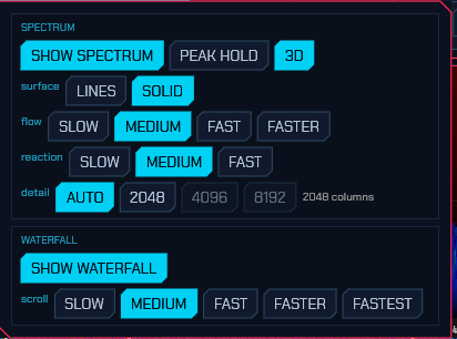
SPEC — opens the panadapter popup, which holds everything the panadapter is drawn by, in two boxes: one for the spectrum line across the top, one for the waterfall under it. The button is lit while both layers are shown.
In the Spectrum box:
- SHOW SPECTRUM — draw the spectrum line, or leave the height to the waterfall.
- PEAK HOLD — trace the highest level each column has reached over the live line, decaying back down.
- FILL — colour the band under the spectrum line. The colour is set in Settings → UI → Spectrum line. Off by default; not drawn on the 3D surface.
- 3D — draw the spectrum as a receding surface instead of a flat line, with the newest spectrum across the front. See The 3D spectrum below.
- surface — how that surface is drawn: LINES or SOLID. Greyed until 3D is switched on.
- flow — how fast it flows away from you, and so how much time the surface holds. Greyed until 3D is switched on.
- reaction — how quickly the line follows the band: Slow, Medium or Fast. Slower averages more frames into each other, which steadies the line and holds a weak carrier still long enough to read. The waterfall is not touched by it — those rows get every frame either way. It steadies the 3D surface by the same amount, which is built from the same numbers.
- detail — how many columns the panadapter and its waterfall are drawn with; the width in force is named beside the button. See Panadapter detail below.
- line — how the FILL colour is shaded: FIXED (one colour throughout), GRADIENT (full at the bottom, fading out towards the top) or MIXED (full in the lower half, fading across the upper half). Greyed until FILL is switched on.
In the Waterfall box:
- SHOW WATERFALL — draw the scrolling waterfall, or leave the height to the spectrum line.
- scroll — how fast it scrolls. See Waterfall scroll speed below.
- DECODE LABELS — mark every decoded station on the waterfall with its callsign, at the frequency it was heard on, in FT8, FT4 and the other slotted modes. On by default. A good opening puts thirty boxes across the span twice a minute, over the very traces you are reading; switching them off leaves the waterfall as the band alone, and the decode list beside it still has every callsign. The CW skimmer’s own boxes are separate — they are switched under SKIM.
The two SHOW switches are independent, so all four displays are available — spectrum only, waterfall only, both, or neither.
- With one of them off the other takes the full height, with the frequency scale still along its edge; dragging that scale brings the hidden layer back at the split you drag to. Skimmer and spot boxes move onto the spectrum while the waterfall is off.
- With both off there is no panadapter at all. In a mode with an operating panel under it — the digital modes, and CW — the panel takes the whole height; in the other modes the area is simply left empty. The SPEC button is the way back.
Detail and the two speeds are this screen’s own preference rather than the radio’s: a remote client picks its own, and neither the station nor another client is touched. They are remembered between sessions.
-
WIDE — show or hide the full-band strip: a shallow second waterfall above the panadapter covering everything the receiver can see at once, with a blue outline around the slice the panadapter is receiving and an amber line on the tuned frequency. A scale along its top labels round frequencies across the band and both of its limits — the lowest and highest frequency the strip covers, named in MHz at the two ends, so it is always clear what the strip is showing. Click anywhere on it to tune there. Hovering it shows a crosshair and the frequency under the cursor, and shift+drag measures a span across it, both exactly as on the main waterfall. The button appears only on receivers that produce a full-band view — a direct-sampling front end such as the RX-888, a KiwiSDR, a SpyServer; on an RTL-SDR, HPSDR or TCI radio the panadapter span is all the hardware delivers — and the setting is remembered between sessions.
On such a receiver the main panadapter can be zoomed out into the strip’s window too, past the I/Q the front end is streaming: keep zooming and it goes on widening until it covers everything the strip does, drawing those spans from the same full-band bins. That matters most where the I/Q is a narrow window onto a wide band — a KiwiSDR sends about 12 kHz of I/Q and a picture of the whole 0–30 MHz, and without this the panadapter could only ever show the 12 kHz. The picture coarsens at the moment it crosses over, because the full-band bins are all there is out there; zoom back in and the I/Q’s own resolution returns. A window too narrow for those bins to resolve is never drawn from them — a KiwiSDR’s are 29 kHz apiece, and a few kilohertz pooled out of one of them would be a flat line — so the I/Q keeps the picture wherever it has anything to say.
Zooming back in somewhere else brings the receiver with you. On these front ends the panadapter is the receiver — there is no looking without listening — so a zoom onto a signal you spotted while zoomed out is read as a request to hear it, exactly as clicking the strip would be. Without that the panadapter would go on drawing from the coarse full-band bins however far in you zoomed, because out there those really are the only bins covering what you are looking at. Panning about while still zoomed out never retunes anything. The strip is not shown in the digital modes, whose layout gives the height to the operating panel instead.
- FIT — keep the waterfall floor and ceiling set for the best contrast. Lit, the levels are refitted by themselves: when you change band, once a pan or zoom has settled, and whenever what the band is doing has drifted far enough that the waterfall has gone flat or blown out. An automatic refit is eased in over about five seconds, aimed at a rolling average of the levels, so a station coming up for a moment doesn’t move the contrast — and no more than one refit is started every five seconds. Switching FIT on fits at once, which is also how to ask for a one-off fit: click it off and on again. Switching it off leaves the levels wherever you set them (the floor and ceiling in the VIEW popup are yours to keep only while FIT is off, and so is the level slider beside the waterfall — see Waterfall level).
-
CTR — keep the tuned frequency in the middle of the panadapter. Lit, the window slides under the dial every time you tune and every time you zoom, so the marker stays put and the band scrolls past it. It is off for a new station, and a radio keeps whichever way you leave it. With it off the window holds still and the marker travels across it until the dial leaves the span, at which point the picture jumps a whole window at once.
Zoomed in this costs nothing: the window is a viewport onto a wider captured span, and the receiver is never disturbed. Zoomed all the way out there is nowhere left to slide, so the receiver’s own centre follows the dial instead — the same thing a drag that reaches the edge of the picture already does. A radio whose centre is its dial (a transceiver on a sound card, an Icom sending its 12 kHz I.F.) is centred to begin with and has nothing to do.
Switching CTR on centres at once, which is also how to ask for a one-off “put me back in the middle”: click it on, and off again if you would rather pan and zoom where you like. A pan is still left where you put it — only tuning and zooming bring the marker home.
- SKIM — opens the skimmer popup (per-skimmer on/off and squelch); lit while any skimmer runs. See Skimmers.
- SCAN — opens the scanner window; lit while a scan is running, green while it has stopped on a signal. See Scanning.
VIEW module:
- floor / ceil — the waterfall’s dB range, one slider each. Bring the floor up until the noise just darkens and the ceiling down until the strongest signal you care about reaches full colour; FIT above does both at once from what is on screen, which is the quicker answer when a band change has moved the whole picture. The same two numbers are on the level slider beside the waterfall, for a quick drag without opening this popup.
- FLIP — scroll the waterfall upwards, newest row at the bottom, instead of the default top-to-bottom. The V key does the same.
-
FFT size —
2048,4096,8192,16384,32768,65536or131072. This is the FFT over the whole of what the radio streams, and the panadapter grows it with the zoom until it runs out.A word on what the larger sizes buy. The transform is pooled down to the panadapter’s own columns — 2048 of them by default, more on a screen that can show more (Panadapter detail, on the SPEC popup) — so up to that width a bigger FFT is more columns, and past it, it is sharper ones: each column becomes the strongest of more bins, so a weak carrier stands further out of the noise instead of being averaged into it. That is why the largest sizes are worth having on a wide front end and do nothing at all on a narrow one, where the size is capped by the rate regardless (a transform may not cover more than a tenth of a second of signal, which on an Icom’s 24 kHz I.F. is 2048 whatever is lit). Past that, zooming in gets a window of its own: the visible span is mixed down and decimated to its own width before it is analysed, so the detail you see follows the window you are looking at rather than how wide the front end happens to be. It matters most on a receiver that streams a lot — an RX-888 asked for 8.1 MHz has 247 Hz to a bin even at
32768, which used to draw a 60 kHz window out of 240 numbers and step visibly. Nothing to switch on, and nothing is given up: the rest of the band is still there when you zoom back out.Two side effects worth knowing. Narrower bins hold less noise, so the noise floor drops as you zoom in — FIT keeps up with it, and with FIT off you may want to re-set the floor. And a fine window takes longer to fill (resolving a hertz needs a second of signal, on any receiver ever built), so a very deep zoom scrolls more slowly than a wide one.
That second one used to be paid twice over. Asking for a finer picture also asked for a longer one, because the transform that drew a point under every column had to cover however many seconds of band that resolution needed — and on the narrow windows the digital modes are watched in, that was several. Each row of the waterfall was an average of the last few seconds, so an FT8 transmission drew as one unbroken bar with no beginning and no end, and turning the FFT size up made it worse. The two are separate now: how much signal a transform looks at is chosen from the window on screen — about a third of a second on the FT8 sub-band, which is what WSJT-X’s own waterfall uses — and the size you pick decides how many points that answer is drawn on. A deep zoom still gets every bit of the resolution it asks for; what it no longer gets is the smear that came with it.
- FLIP — scroll the waterfall upwards (keyboard shortcut V). The newest line is drawn at the bottom and history flows up off the top, the way several other SDR programs draw it. The minute gridlines, the skimmer / FT8 boxes, the cluster-spot boxes and the band-plan strip all follow the flip, so the fresh decodes stay next to the fresh signals and nothing covers the newest lines. The setting is remembered between sessions.
- FLATTEN — level the noise floor across the band. A radio’s own noise is rarely the same everywhere, and the FIT chip sets one floor for the whole picture, so a quiet stretch of band goes black under a level that was fitted to the loud half. FLATTEN raises those quiet stretches towards the floor their neighbours sit at, and a weak signal on a busy band becomes visible again. Two things it deliberately does not do, both on the chip’s hover: it only ever raises, so a carrier is never pushed down toward the floor and signal is never flattened away to make a picture prettier; and it never raises by more than 20 dB, so a stretch of spectrum genuinely below your radio’s own noise is not pumped up until it looks like signal. The spectrum trace above the waterfall is left exactly as measured, and the lift eases in over about a second rather than snapping, so it does not flicker with a neighbour keying. On by default; click it off for the bare measurement.
The waterfall colour scheme and the spectrum background gradient are set
on the UI tab of the Settings window (see
§6.3). The colour scheme is one of
Classic, Viridis, Gray, Icom, Neon, Synthwave, Matrix, Tron,
Amber, or Rainbow;
the gradient fills the spectrum area from a top colour down to a bottom colour
(default dark red → black) and can be turned off. The same tab also themes the
UI itself — colour theme, button shape and window shape — independently of the
waterfall’s palette; the screenshots in this manual show the Default theme.
The frequency-scale strip between the spectrum line and the waterfall is both a divider and an axis, and a drag on it picks one the moment it has a direction: up and down resizes the split between the two layers, sideways slides the band along under the picture. The sideways drag moves the window and never the dial — it is how to look somewhere else without leaving the frequency you are listening to — and once the view is the whole span it takes the receiver’s own centre with it, so it keeps going rather than stopping at the edge. Either layer can also be hidden altogether from the SPEC popup in the Display module.
The scale carries a labelled frequency every hundred points or so with unlabelled ticks between them, so a wide panadapter gets more markers to read against than a narrow one rather than the same handful stretched across it.
Waterfall level
A thin vertical slider sits on the right edge of the panadapter, beside the waterfall: the SDR-style level control, without opening a popup.
- Drag it, or scroll over it, and the floor and ceiling move together — the picture brightens or darkens and the contrast is left alone.
- Shift-drag or shift-scroll moves the two ends apart or together, which sets the contrast.
- Moving it turns FIT off: a hand on the level is a manual override, and an automatic fit would otherwise walk it back. Click FIT to hand it back.
- Hover it to read the floor and ceiling in dB.
It writes the same db_floor and db_ceil as the VIEW popup’s sliders and the
keyboard bindings, so all of them agree. On a window too small to spare the
column — a phone, or a very narrow pane — it is not shown, and the popup
sliders are still there.
Panadapter detail
How many columns the panadapter and its waterfall are drawn with, on the detail row of the SPEC popup. AUTO is the default and is what nearly everyone should leave it on: it reads this machine’s graphics — the largest texture it will hold, whether it is drawing on a real GPU or in software, which renderer is in use, whether the radio is across a network — together with how wide the panadapter actually is in pixels, and picks the most the machine can carry. The number it settled on is shown beside the buttons.
The steps are 2048, 4096 and 8192 columns. 2048 is what every sdroxide before this one drew, and about what a 1080p panadapter can show; 4096 is one column per pixel of a 4K panel, which is the point of the setting; 8192 is two per pixel, which keeps a carrier sharp while the view is panned off the pixel grid. A step this machine cannot hold is shown greyed, with the reason on hover — a Raspberry Pi, an older graphics chip, a browser without WebGPU and a machine drawing without a GPU at all are all held to 2048, because a wider waterfall there costs the frame rate and buys a picture the renderer cannot draw anyway.
AUTO stops at 4096 even on a very large screen; 8192 is there to be chosen. AUTO also stays at 2048 when the radio is on the other end of a network, because every column is a byte in every frame — 4096 columns at 60 fps is about a quarter of a megabyte a second — and there is no way to measure the link from this end. On a LAN, set it by hand.
Detail costs memory on the graphics card: 8 MB per radio tab at 2048, 16 at 4096, 32 at 8192. Changing it restarts the waterfall’s history from black, once.
The 3D spectrum
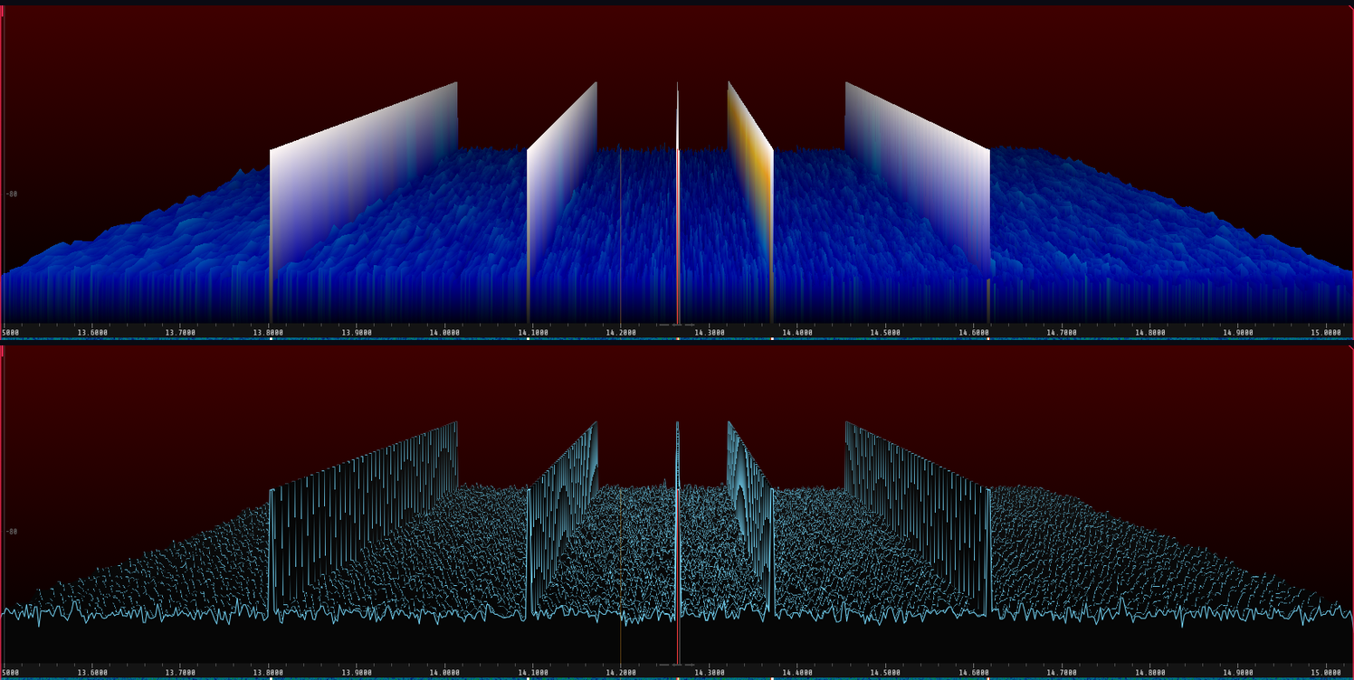
The 3D button in the SPEC popup swaps the flat spectrum line for a receding surface: the newest spectrum lies across the front at full width, and the ones before it flow away from you, narrowing towards a vanishing point. The last few seconds of the band are on screen at once as a landscape — how many is the flow row below — so a carrier that comes and goes reads as a ridge with a length to it rather than as a line that twitches, and a signal a couple of dB out of the noise is a bump you can follow backwards in time. The waterfall says the same thing in colour; this says it in shape.
The surface row picks between the two renderings:
- SOLID fills the surface and colours it by the same palette the waterfall uses, so the level is in the colour as well as in the height and the two halves of the panadapter agree about what a strong signal looks like. Change the palette in Settings › Display.
- LINES draws one trace per remembered spectrum in the flat line’s own colour: the shape without the levels. It strokes a line over the same surface SOLID fills, so a column costs it more — and because both renderings are held to the same drawing budget, it is given fewer of them. That makes it the coarser of the two across the band, and the cheaper of the two to draw.
The flow row sets how fast the surface travels: Slow (6 rows a second), Medium (12), Fast (24) or Faster (48). The surface is a fixed 48 rows deep, so this is also how much band it holds — eight seconds at Slow, one at Faster — and the two ends of the row are two different instruments. Slow is a memory: a signal that came up once in the last few seconds is still on screen to be looked at. Faster is a motion display: the surface moves visibly, which is what makes a fade or a keying pattern something you watch rather than something you infer. The rate is in rows a second and not rows a frame, so the picture is the same on a browser client at 30 fps as on a desktop at 60; past the frame rate the extra rows are copies, which is why the buttons stop where they do. The waterfall keeps its own scroll rate, and neither touches the other.
Both hide what is behind them, which is what makes the picture read as depth: a strong signal in front stands over the band it is covering, and a flat stretch in front lets the rows behind it show over the top. The dB scale down the left edge belongs to the front row — the newest spectrum — and so does everything else drawn on the spectrum: the passband wash, the filter edge grips and the tuning lines are kept to the front of the surface rather than cut through rows the filter was never set on. The flat grid and the PEAK HOLD trace both describe a single line and are not drawn at all while the surface is; the surface brings its own floor and its own amplitude axis instead.
This is drawn on the client — the browser client has it too, on the same buttons — and it is off by default. It is not free, and it is the one display here that can double the client’s own processor load: measured against the flat line on the same band, at 60 frames a second and a 1696-point-wide panadapter, 35% of a core for the flat line, 70% for the solid surface and 52% for the line one. Nothing reaches the radio, though — no extra work is asked of the engine, and nothing more goes over the link to a remote station, so a client that is struggling cannot slow the station down.
Waterfall scroll speed
How fast the waterfall scrolls, in lines a second, on the scroll row of the SPEC popup: Slow (5), Medium (28), Fast (56), Faster (112) or Fastest (224). Faster trades screen time for vertical resolution, which is what you want when a CW or FT8 trace is smearing into the line above it; Slow keeps several minutes of band on screen at once.
The two fastest settings are past the rate any screen redraws at, and that is deliberate: the radio clocks the waterfall’s lines itself rather than one per redraw, so 224 a second is 224 different lines rather than 56 of them drawn four times. Each line is also the strongest thing its slice of time contained rather than a snapshot at the end of it, so a CW dot or the edge of a burst that is shorter than the gap between two lines still gets drawn instead of falling between them.
What limits it is the receiver, not the screen. A line can never show more
than one transform of the FFT, and a front end produces sample rate ÷ half
the FFT size of those a second — an RX-888 at 8 MHz through a 32768-point
window makes about 500, so it can feed any of these settings, while a 24 kHz
I.F. through the same window makes under one and repeats lines at every
setting. Two costs worth knowing: the waterfall keeps a fixed number of
lines, so history shortens as the rate rises (73 seconds at Medium, 9 at
Fastest), and to a remote client every line is a byte per column on the
link.
2.9 The S-meter
The S-meter reads S0 (−127 dBm) through S9 (−73 dBm) and beyond, turning red
past S9. It shows the S-unit (for example S9+20) and the level in dBm.
S-Meter calib (Settings → Radio, under Antenna is) corrects a meter that reads too high or too low, per radio: −5 to +5 S-units of 6 dB, 0 being the meter as measured. A noise floor shown at S5 where it should be S2 wants −3. Only the reading moves — the needle, the S and dBm figures, the level a reception report starts from and the spoken S-meter. The signal, the squelch, recording and the decoders are not touched. It is saved with the radio on the machine it is attached to and takes effect at once.
Where the dBm normally sits you may instead see OVL in red. That is the
converter clipping: the signal reaching it is bigger than it can represent, and
everything downstream is reading a distorted version of it. The dBm is taken
away rather than shown beside the warning because it is no longer a
measurement — a clipped carrier reads lower than it really is, so the number
would be arguing with the warning next to it. Turn the RF gain down, or switch
in an attenuator, until it goes.
It is worth taking seriously even when nothing sounds wrong, because on FM almost nothing will: the audio stays clean well past the point where the data riding above it has already gone. See the RDS diagnostics tab (2.7) for the same warning where its effects show first.
OVL answers to two different measurements, and either one lights it. The
first is what sdroxide measures here, from the samples the radio sends: how many
of them sat at full scale over the last meter window. The second is the radio’s
own overflow flag, on the few front ends that report one — a Hermes Lite 2
does. That second one matters on a direct-sampling radio, where the converter
takes a whole band at once and then hands over a narrow slice of it: a
broadcaster three bands away can be driving the ADC into its rails while every
sample that reaches sdroxide sits at a tenth of full scale, so only the board
can tell you. A Hermes Lite 2 can also be left to fix it by itself — see
Overload protection in 6.2.3.
Board temperature. A radio with a temperature sensor of its own has the reading in the meter’s bottom-left corner, in degrees Celsius — a Hermes-Lite 2 is the one this driver meets that reports one, on every face and in receive as well as transmit. It is grey in normal use, amber past 55 °C and red past 70 °C. Those are attention thresholds and not limits the radio enforces: it is the board’s own sensor beside the output stage, so it lags a key-down by some seconds and reads below the transistors themselves. What it is good for is the slow half — an HL2 running FT8 all afternoon heats up and stays hot, and this is where that shows. A radio with no sensor shows nothing here.
Clicking the meter cycles three faces:
- Needle (the default) — an analog moving-coil instrument. The needle has a little inertia, so it swings into a reading and settles the way a real movement does.
- Bar — a horizontal gradient bar with a graduated scale beneath it and a peak-hold marker that falls back after a moment.
- Trace — the last fifteen seconds plotted as a scrolling graph, which is the one to watch for fading and QSB.
The face you pick is remembered. It belongs to the screen rather than to one
radio — it is written to smeter_style in the [ui] table of config.toml the
moment you click, so it survives a restart however the last session ended, and
every radio comes back up wearing it.
On transmit all three switch to a transmit meter, stacked in two rows. The top row is ALC. On a rig that reports its own ALC over CAT — Icom CI-V rigs do — that is the rig’s figure, which is the one that answers “am I overdriving it”; on anything else it is sdroxide’s own drive level, which is how hard the audio being sent is driving the modulator. The two are different measurements, and on a CAT rig driving an external radio only the rig’s says anything about whether the audio is too hot for it.
The lower row is whichever meter the rig actually gives us. Where the rig reports a power-output meter it goes there, as a percentage of the rig’s own full scale rather than in watts — Icom calibrate that meter’s face in percent, with no calibrated wattage behind it, and the relation to watts moves with band, mode, supply voltage and drive, so a wattage would look measured without being so. It answers what the drive slider cannot: the slider is what the rig was asked for, and this is what it is delivering. The two part company whenever the rig folds back — heat, a high SWR, or an ATU still hunting. The ramp carries no red, because a rig at full output is doing what it was asked; what you are watching for is the needle falling while drive stays put.
Where there is no power meter but there is an SWR bridge, the lower row is SWR instead, on a logarithmic scale with 1:1 at the left stop, 3:1 at mid-scale and everything past 3:1 in red. Either way the SWR keeps its place as a number in the header button. Rigs with neither show the drive row alone, grown to fill the space.
Hover the meter and it says what it is showing. The face is dense — a chip, a figure, one or two bars and a scale — and a needle sitting at 50 during an over does not say by itself whether that is half the power, half the modulation or something else. The tooltip names each quantity and its units, and on transmit it says outright when the radio measures nothing: an SDR that sdroxide modulates itself — a HackRF, a Pluto, a LimeSDR, an RTL-SDR-class transmitter — has no SWR bridge and no power sensor at all, so those rows are absent because there is nothing to put in them rather than because a reading has gone missing. SWR and forward power appear when the radio measures them: a rig over CAT, TCI or a LAN link, or an HPSDR board.
Where the reading comes from depends on the interface. An SDR delivers IQ and
the receiver measures the signal in its own passband, calibrated to dBm by
cal_offset_db in config.toml.
cal_offset_dbstarts at 0, which means an SDR’s meter starts out reading dBFS — how loud the signal is against the converter’s full scale — with a dBm label on it. On a receiver with plenty of gain ahead of an 8-bit converter, an RTL-SDR among them, its own noise sits high enough on that scale to read S9 with nothing plugged into the antenna socket. Nothing is wrong with the receiver; the scale has not been told where zero is. Setcal_offset_dbto the difference between what the meter shows and a level you know — a signal generator, or a band-noise reading you trust — and it will read in dBm from then on. It is one number for the station, so where two radios differ, set it for the one you judge signals on. Changing the front end’s gain moves the reading with it, exactly as an attenuator ahead of a real receiver would.Except on an SDRplay RSP, which is the one front end here that reports what its own gain currently is. That figure is taken off before the reading is shown, so the meter is referred back to the antenna socket: it stays put when the gain moves, and it stays put while the RSP’s own AGC — on by default — moves it for you. What that costs is that the numbers are tens of dB lower than the same RSP showed before, because they no longer have the front end’s 20 to 60 dB of gain in them. They are the more honest number, and
cal_offset_dbset for an RSP before this has to be set again. See 15.15.The same applies with a knob more in the way when the I/Q arrives over a virtual audio cable from another program (PowerSDR, HDSDR): what the meter measures is the level that program is writing into the cable, which it has already put through its own gain and AGC. A reading tens of dB above the S meter in the program feeding it is that offset and not a fault — set
cal_offset_dbto the difference and the two agree.
A CAT rig on a sound card sends audio it has already demodulated and levelled, so there is nothing left on this side to measure: Icom rigs are asked for their own S-meter over CI-V instead, which is the reading on the radio’s front panel, and rigs whose CAT dialect has no meter read fall back to the level of the audio itself — that one follows the signal but is not calibrated in dBm, being whatever the rig’s AGC left.
2.10 Transmit
On a TX-capable rig the Transmit module appears:
- PTT — key the transmitter.
- TUNE — send a carrier at the tune-drive level for tuning an ATU.
- Drive — transmit drive (0–100%). One number for every band; if your amplifier makes a different power on each, calibrate it once in Transmit drive by band (Settings → Radio, 6.2) rather than resetting this on every band change.
- Tune — the (lower) drive level used by TUNE.
- Mic — microphone gain.
-
TX audio — how loud a digital mode is handed to a radio that modulates it itself, in dB below full scale. It stands in the Mic rail’s place, and only in the modes where the microphone is not what goes on the air: select FT8, RTTY, PSK or CW-as-MCW on a CAT rig and the rail changes from
Micto a dB reading; go back to SSB and Mic returns. The two can never both apply — in a digital mode the microphone is drained and discarded, so a Mic slider there would move nothing — and the strip has room for one rail, so it shows the one that works. (FreeDV RADE is the exception on both counts: the microphone is the payload there, so RADE keeps Mic and reaches this level from the TX menu.)This level is kept per mode. FT8, RTTY, PSK and MCW do not load a transmitter the same way, and the figure you are setting is where your waveform sits against the radio’s ALC — so each mode remembers its own, saved as you set it. A mode you have never touched starts from the level for the carrier it goes out on, which is also what a mode added in a later release inherits, so nothing ever comes up at full scale behind your back.
The adjustment on sideband is: bring it down until the rig’s ALC is barely moving, then set the power at the radio. ALC riding on a constant-envelope digital mode is what splatters. On FM — VHF packet, APRS, RIFP — the same control is the deviation instead: an FM transmitter turns audio level into frequency swing and has no ALC to catch it, so full scale into a data input set for voice over-deviates, which sounds completely normal to anyone listening and decodes for nobody. Turn it down until other stations report you, or set the level at the radio.
The same control is in each mode’s setup window, where there is one, and the radio’s own input level is the other half of it either way.
On a radio sdroxide modulates itself — a Pluto, an HPSDR board, an SDR — none of this applies and the rail does not appear: there the modulator and Drive own the level.
Transmit EQ (Settings → Radio, above the per-interface section, since it applies the same way whichever radio interface is selected) is a 3-band parametric equalizer on the microphone audio, ahead of the modulator: Low shelf (cuts/boosts rumble and handling noise), Mid peak (presence, a narrow bump or dip somewhere in the voice band), and High shelf (brightness/de-ess). Each band has its own frequency and gain (dB), and the mid band also has a Q (how narrow the bump is) while the two shelves have a Slope instead (how sharply they roll off). Off by default, and flat (0 dB every band) the first time you turn it on, so enabling it changes nothing until you actually move a slider. Voice modes only (SSB/AM/FM); digital modes and CW carry synthesized or keyed audio that never reaches it. Applies immediately, like the IARU region setting: there is no Apply step — including while you are transmitting, so you can set it by ear against the transmit monitor.
It sits after Mic gain and before whatever modulates the audio, on every interface: a radio sdroxide modulates itself, and a rig that modulates its own audio (a CAT rig over its sound card, TCI, Icom LAN, SmartSDR) alike. Boosting a band therefore raises the level going into the transmitter, and there is nothing behind it but a limiter at full scale — on a transmitter, clipping is splatter on your neighbours’ frequencies. After boosting anything, watch the ALC/TX meter and take the same amount back off Mic gain. Cutting is free; a cut band and a little more mic gain gets the same tone with none of the risk.
Transmit safety: by default sdroxide refuses to transmit outside the amateur bands (
tx_ham_only), and stops the transmission if the radio reports a high SWR (swr_guard, below). Transmit hardware gains start at minimum and the tune drive defaults low. Raise drive deliberately. The one exception built in is the 11 m citizens’ band — a transmitting service, but not an amateur one — which opens when the station switches on Allow transmit on 11 m (CB) (confirmed once); it opens 11 m and nothing else. The general band lockout can otherwise only be lifted from the command line, one run at a time, with--oob-tx(12).
The SWR guard stops the over when the antenna system is not what it should be — a feeder that has come off, a coax switch left on the wrong port, a dipole leg that has parted in the wind. It is armed by default at 2.5:1 and is set in Settings → General (6.1).
- It needs a rig that measures SWR and reports it over CAT or TCI. On an IQ radio there is no such reading, and the guard is inert rather than approximate.
- It does not wait for high power. A rig with SWR foldback answers a bad match by dropping to a few watts, so a power threshold would gate out exactly the emergency; the first fifth of a second of each over is ignored instead, on the clock, to ride out the key-up transient.
- When it fires the transmitter stops and transmit stays locked out until you press Acknowledge on the warning bar. That is deliberate: a latch you can clear by pressing PTT again is not a latch. Turning the guard off also clears a standing trip.
- The banner names the SWR that fired it, so you know whether you are looking for a bad connector or a completely disconnected antenna.
TUNE is treated differently, because feeding a mismatch is the whole point of it. An antenna tuner has nothing to work on until the rig keys into the very mismatch the tuner exists to remove, and a sweep that begins at 10:1 is what tuning looks like. So a tune gets double the limit — 5:1 with the default 2.5:1 setting, shown next to the figure in Settings so you never see a number you cannot find — and about five seconds before the guard applies at all, instead of a fifth of one. What survives is the case worth keeping: a feeder that is simply not connected still reads at the top of the scale once the tuner has had its five seconds, and still stops the carrier.
A manual tuner can easily take longer than five seconds to find a match. That is the one case the guard gets wrong, and the answer is to turn it off for the session rather than to raise the limit — you are deliberately sitting at a high SWR for as long as it takes, which is the situation the guard exists to end.
On a rig with its own power control — a TCI rig, or a CAT rig on any of the three dialects — Drive and Tune command the rig’s output power directly rather than scaling anything on this side, and the slider adopts the rig’s own setting when sdroxide connects: a level set in ExpertSDR3, or on the radio’s front panel, carries over instead of being overwritten. The level that applies is asserted before every over, including a CW message handed to the rig’s own keyer — which is the one place where the rig’s power is the only transmit control there is, the sound card having no part in CW at all. After a TUNE the operating level is put back, so the radio is not left at the tune level for the next call.
The level is asserted behind the mode, not only when you move the slider, because a rig keeps its output power per mode: a radio set to 100 W in USB and 25 W in USB-DATA transmits at whichever of the two the mode command last left it in, and one put into AM is held to a quarter of its rated power on top of that. So a mode command and a power command go out in that order at every key-down, and the level lands in the register the over will actually transmit on. This matters most on a quadrature rig, where sdroxide demodulates the I/Q itself and the radio only learns which mode to transmit in when the transmitter comes up: there every over changes the rig’s mode, and so the register its power comes out of.
On a CAT rig the power is a fraction of what the radio can do. Icom carries it that way natively; Yaesu and Kenwood take a number of watts and have no way to say how many they have, so their sliders are read against 100 W — right for nearly every rig those dialects cover, and low (never high) for the few that go above it, such as an FTDX101MP or a TS-480HX. Elecraft takes watts too but can be asked: the option-module query at connect says whether there is a KPA3 or a KXPA100 on the end of the cable, which is the difference between a slider that spans 110 W and one that spans a KX2’s 12.
Drive and the hardware’s TX gain are not the same control. On an IQ radio — a Pluto, an HPSDR board, an SDRplay or a SoapySDR device — Drive is digital: it scales the modulated baseband on its way to the converter, with a hard limiter at digital full scale so it cannot overflow. The radio’s own output level is a separate slider on the Radio tab (TX gain, or whatever that device calls it), and the two multiply. Set TX gain once for the antenna and the amplifier you are feeding, and use Drive as the level you actually work with; the sensible starting point is Drive near the top and TX gain low, not the other way around, because backing off in the digital domain throws away converter resolution and Drive is the one with the limiter behind it.
What Mic gain does depends on the mode. In SSB it sets how hard the microphone drives the modulator, so Drive and Mic between them decide both level and how much the limiter is working. In FM it sets deviation — sdroxide’s FM modulator is constant-envelope, so Drive changes the power and does nothing to the audio, while Mic gain alone decides how wide the signal is. 50% is unity gain, which puts a full-scale recording at the ±5 kHz peak deviation NFM wants; higher over-deviates and distorts however low Drive is. In FreeDV RADE it sets how hard the microphone is fed to the vocoder, the same 50% being unity. In every other digital mode it does nothing at all — the burst is synthesized and the microphone is discarded — which is why the rail becomes TX audio there.
CESSB — more average power for the same peak. The CESSB rail is controlled-envelope single sideband, David Hershberger W9GR’s 2014 technique. It is the second vertical rail in the Transmit module, standing beside Mic on a desktop window, and a rail in the TX menu on a tablet or a phone. The thing an amplifier runs out of is the envelope — the magnitude of the sideband signal — and that is not the audio waveform, so a limiter on the microphone does not limit what the amplifier sees. The envelope of clipped speech overshoots by a long way, an SSB transmitter has to be backed off for peaks nobody hears, and the average power reaching the far end is a fraction of the transmitter’s rating.
CESSB works on the envelope directly: it clips it, filters the resulting splatter away, and then removes the peaks the filter put back by subtracting a band-limited copy of the excess — a subtraction rather than a gain, which is what keeps the transmission inside your own filter instead of spreading it to twice the width. The measured result here is about 3.8 dB more average power at the same peak at 9 dB of compression, with out-of-band energy at the arithmetic’s own floor.
The control is one number: how many decibels the voice is driven into the processor, 0 being off, which is where it starts. 6 dB is a sensible first try and 9 dB is about as far as most voices want to go — past that it starts to sound like a processor rather than like you. It is set by ear, remembered per radio, and it does not touch Drive: what leaves the processor is still held at full scale, so your power setting means what it did before.
It applies where sdroxide makes the sideband itself — an HPSDR board or Hermes Lite 2, a Pluto, a LimeSDR, a SoapySDR device. A transceiver that modulates the audio from its own sound card is making the envelope in its own DSP, where this cannot reach it. The rail is drawn where it can do something and nowhere else, so on such a radio — or in any mode but voice USB and LSB, whose payload is the envelope this flattens — there is no CESSB rail to find.
2.11 Voice keyer
The ▶ button in the Transmit module opens the voice keyer: ten recorded messages you can put on the air with one press — a CQ call, your callsign, a contest exchange, a 73.
Each row is one slot:
- Type a name for the slot (optional; it is just a label).
- REC records from your microphone. Press it again to stop and store the message; recordings stop by themselves after two minutes.
- PLAY plays the message back through your speakers so you can check it. Nothing is transmitted, and it replaces the receive audio while it runs.
- TX keys the transmitter, sends the message and unkeys at the end. STOP ends it early — so does pressing PTT, TUNE, or Abort transmit.
- ✕ erases the recording.
Recordings are stored as plain 48 kHz mono WAV files in
~/.config/sdroxide-brown/voice (see 12. Configuration files),
one per slot, so you can also record a message in an audio editor, name it
slot3.wav, and drop it in.
Triggering a message. Out of the box the digits 1–9 and 0 play slots 1–10 and − stops one; on a full keyboard those are the numpad keys (the platform reports numpad and top-row digits identically, so either works). Like every other binding these can be changed — or moved onto a MIDI pad or footswitch — on the Controls tab; see 6.4. A key over an empty slot does nothing at all, which is why the digits can ship bound when PTT deliberately does not.
External programs can trigger the keyer too: with the built-in Hamlib server
running (6.9),
\send_voice_mem <1–10> plays a slot and \stop_voice_mem stops it.
NOTE: The keyer is available in every voice mode and in RADE digital voice, where the message is fed to the codec exactly as a live over would be. The other digital modes generate their own transmit audio, so the button is hidden there (and the window closes if you switch into one). Recording is refused while you are transmitting — it is the same microphone.
2.12 Memory channels
Open MEM (System module) for the memory channels window. Type a name and press Store to save the current frequency and mode. Each saved row has a RCL (recall) button, an EDT (edit) button and a DEL (delete) button.
EDT turns the row into an editor: the name, the frequency in MHz and the mode, with SAVE to keep the change (Enter does it too, from the name field) and ✖ to abandon it (so does Escape). It is the same channel afterwards — same place in the list, same folder — so correcting a typo, or a frequency that has moved, costs one edit instead of a delete and a fresh store from that frequency. The filter follows the mode: change the mode and the channel takes the new mode’s default passband, leave the mode alone and a filter you chose yourself is kept.
On a receiver with more than one antenna port the editor has an antenna drop-down as well: which socket this channel is listened to on. Storing a memory captures whichever socket the radio was on at the time, and this is where you say it should have been another — the wire for a 40 m net, the beam for a 2 m repeater. The dash (—) is not the first port: it means leave the antenna alone, and it is what every channel stored on a single-socket receiver holds, so working down a list that never mentioned antennas never moves a relay. The socket is shown in square brackets at the end of the row. A receiver with one antenna has nothing to choose and gets no drop-down.
The editor also carries a RPT button, which folds out the repeater set-up
stored with the channel: the shift and its offset, the CTCSS tone or DCS code
to transmit, and whether every over opens on the 1750 Hz burst. A channel that
already has one comes up with the section open. Storing a memory captures
whatever the DUPLEX and TONE controls are set to at the time — including plainly
simplex with no tone, which is what lets the next recall take a shift back
off rather than leaving the last repeater’s on a simplex channel. Every
recall sets DUPLEX and TONE, including a channel from a memories.json
written before this existed and one whose RPT section was never opened: those
are read as plain simplex with no tone, because that is what the list is
showing you. The list shows what is stored beside the mode, so two memories on
one dial read as the different channels they are. See
2.18 Repeater operation.
Importing and exporting a channel list
IMPORT reads a channel list from a CHIRP CSV file (.csv) — the format
CHIRP writes and the one every repeater directory hands out. RepeaterBook
exports it by county, most national societies publish their machine lists in it,
and the marine, PMR and aviation channel tables circulate as it too, so a list of
local repeaters is usually one download away rather than four hundred stores.
Each channel brings its frequency, its mode, the repeater shift and offset, and the CTCSS tone or DCS code to transmit. A channel already on the list — same frequency, same mode — is skipped, so re-importing an updated directory adds what is new instead of doubling what is not; the names of the channels you already have are left alone. A line the file’s own format cannot account for (a blank row, a trailing note, a frequency that is not a number) is skipped and counted rather than failing the import, and the network log at the bottom of the window says how many channels were read and how many lines were not.
The columns are matched by name, from the file’s header row, so a file that carries only some of them or carries them in another order still reads. A file with no header row is refused — its first line would be a real channel, and mistaking one for a heading would silently lose it.
EXPORT writes the list back out in the same format, to load into a handheld
or to keep as a backup. Not everything survives the trip: CHIRP’s format has no
place for a folder, an RTTY modem setup or an antenna socket, and its Mode
column is the modulation, so a channel stored in a digital mode exports as the
sideband it rides on. The frequency, the name, the shift and the tone all do.
The Sort row above the list says what order it is drawn in — Stored (as
stored, the historic order), Name (ignoring case), Freq, or Band
(each band’s channels together, general coverage last, by frequency inside
each) — and the ▲ button reads that order backwards. It is a preference of
this screen, remembered in config.toml under [ui]: the store keeps its
channels in the order they were stored, a memory scan works through them in
that order whatever the list shows, and somebody at another screen on the same
station sorts the same memories their own way.
Memories can be filed into folders. Type a name into the second field and press New folder, then drag a memory row onto the folder to file it under that folder — and drop it on the area below the folders to take it out again. Every folder header has a REN button (rename in place — Enter or clicking away keeps the new name, Escape abandons it) and a DEL button, which deletes only the folder: the memories filed under it move back to the top level. Folders collapse and expand with the arrow at the left of their header, and a memory scan works through every memory regardless of the folder it sits in.
Every memory on the visible span is also marked along the bottom of the
waterfall, as Mem: folder / name — see
2.3 Tuning.
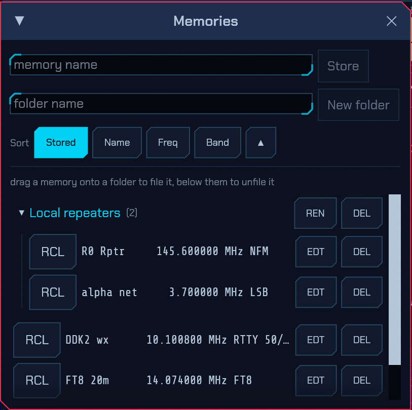
2.13 Scanning
Open SCAN (System module) to work through channels and stop where somebody is transmitting. Two kinds:
- MEM — the stored memory channels, each in its own mode and filter. Mark any of them SKIP to pass it over; a channel that is always busy with something you do not want to hear is what that is for.
- RANGE — a slice of a band on a channel grid. Give it a From and a to in MHz, a Step (5 / 6.25 / 8.33 / 10 / 12.5 / 25 kHz) and a mode.
A range scan is fast, and not in the way a handheld scanner is. A scanner has one receiver and has to visit each channel in turn, which is why sweeping 2 m takes minutes. Here the FFT that already draws the panadapter sees over a megahertz at once, so the radio moves one span at a time and reads every channel in that span together — the whole of 2 m in well under a second. A CAT rig feeding demodulated audio has no such span, so it falls back to visiting channels one at a time, and behaves like the handheld.
A memory scan stops on each channel in its own set-up. Stopping on a channel sets the mode, the filter and the DUPLEX and TONE stored with it, so a scan across a mixed list leaves you on a repeater channel with its shift and tone on and on a simplex one with both off. That matters more here than on a recall, because a scan hands you whichever channel called and you answer it by reaching straight for the PTT — a shift left standing from the last stop would put the over 600 kHz away from the station calling you. A channel stored before the set-up existed counts as plain simplex with no tone, exactly as a recall reads it (2.12). The antenna is the one thing a stop does not touch, unlike a recall: a scan is not worth a relay per channel.
A memory scan can be pointed at chosen folders. With folders in use (2.12) a Folders row appears above the channel list: ALL, then one button per folder with the number of channels in it, and Unfiled for the top level. Pick one or several and the scan runs over those alone — the marine channels while you are on the water, the local repeaters while you are not — and the list below narrows to the channels it will actually visit, so what you are looking at is what the scan will do. ALL is not every button lit: it means no selection, which is also where a folder you make tomorrow lands, so a new folder is scanned rather than silently left out. A folder you delete drops out of the selection with it, since its channels are back at the top level by then. The row is not drawn at all until there is a folder to choose.
FAST reads the list off the spectrum. A memory scan normally does what a handheld does: tune to each channel, listen, move on — a settling time apiece, so a hundred channels is fifteen seconds a lap. Press FAST and a receiver with I/Q of its own instead puts every channel that falls inside one window on the same transform the panadapter is already made from, and only tunes to the ones something is on. A list that fits in one window then costs one tune a lap however long it is, and a list spread over four bands costs four. The scan still listens on each candidate before it stops, so what makes it stop is unchanged.
It is off by default and worth knowing why. The sweep measures a channel through the FFT rather than through the receiver’s own filter and AGC, so a Stops at level that was right for the slow scan is not automatically right for this one — if a fast scan stops on nothing, raise it; if it stops everywhere, lower it. Two kinds of channel are never judged from the sweep at all and always get a listen: one out at the edge of the window, where the anti-alias filter makes everything read low, and one sitting exactly on the receiver’s centre, where a zero-IF front end’s own local oscillator is. A CAT rig feeding demodulated audio has no spectrum to read, so the button is greyed there and its memory scan visits every channel as before.
Stops at is how loud a channel has to be. Either give a level directly, or
press SQL to use the receiver’s own squelch, which makes the scan stop
exactly where the audio would have opened — one control instead of two. Note
that with the squelch slider at off the scan will stop on the first channel it
looks at, since every channel then counts as busy. The squelch is one of the
per-mode settings (see Per-mode settings (the reset chip)), so SQL uses
the squelch of the mode being scanned: a frequency scan in NFM started from
SSB stops at NFM’s squelch, which is open until you set one there, and a memory
scan judges each channel by the squelch of the mode it was stored in. Set it
once while the scan is running in that mode and it is remembered for next time.
Listens for is how long it stays on a candidate before judging it. Below about a tenth of a second the level meter has not settled and weak signals get missed; the default 150 ms is a reasonable balance.
Resumes decides what ends a stop:
- CARRIER — carry on once the signal drops, plus a grace period. The grace is what keeps you on a conversation through the gaps between overs; two seconds is a good starting point.
- TIMED — carry on after a fixed time whether or not the signal is still there. Useful on a channel somebody is sitting on.
- MANUAL — stay until you press NEXT.
While a scan is running, NEXT moves on now and SKIP moves on and adds the channel to the skip list. Touching the dial, changing band, recalling a memory or transmitting all stop the scan where it is — as on any scanner, and so that the radio is not fighting you for the VFO.
SKIP works in a range scan too, and it is remembered. There is no stored channel to mark, so the frequency itself goes on a skip list shown under the range — a row of buttons, one per channel, with CLEAR to empty it. The list is saved with the rest of the settings, so a data channel, a pager or a birdie dismissed once stays dismissed for the rest of the evening and for every later run over the same range, instead of costing a stop every pass. Click a button to put its channel back into the scan.
The list belongs to the range it was taken in: change the From, the to or the Step and it is emptied, because a channel dismissed on 2 m says nothing about 70 cm — and a scanner quietly refusing to stop somewhere you do not remember dismissing is worse than one that stops too often.
The SCAN button in the System module lights while a scan is running, in cyan
while it is sweeping and green while it is stopped on something, so you can
close the window and still see what it is doing. Settings are remembered in
scanner.json.
2.14 CW: decoding and keyboard sending
Choose CW from the Band/Mode popup and the panadapter gains a cursor and a panel underneath it. CW is not a digital mode — the tone stays audible, the waterfall stays on the whole band, and nothing about the way you tune changes — but a decoder reads what you are listening to, and a keyboard sends.
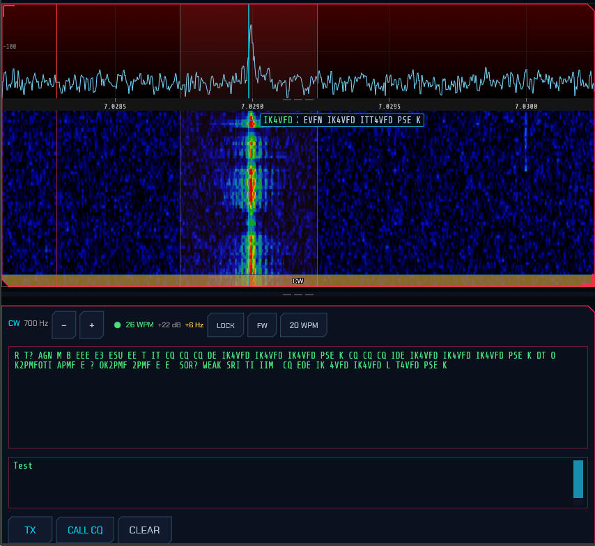
The cursor is the frequency. The cyan line on the waterfall marks the tone being copied. It is also the tone you transmit on, because in CW those are the same frequency: you answer a station where you heard it. Everything follows the cursor together — the passband moves with it, so what is decoded is always what is audible.
- Click a signal on the waterfall to bring it to the cursor. This tunes the dial so the signal lands at your pitch, which is what you want and what a bare click-to-tune does not do: the dial in CW sits a sidetone-pitch below what you hear, so tuning a signal onto the dial itself is the one place it is guaranteed to be inaudible.
- −/+ in the panel header move the cursor 10 Hz at a time. This is your sidetone pitch, a personal preference; you will set it once.
- Clicking a CW skimmer box (4) does the same thing, so a station spotted across the band is one click from being copied.
- The MHz figure after the pitch is the frequency you are working — the dial plus that pitch — and it is what to log and what to give on the air. The logbook’s + NEW ENTRY (3.2.8) fills itself in from the same figure, not from the dial.
-
QRG in the panel header puts the big readout on that figure too. Left off — which is what every other radio does, and the default — the big readout at the top of the window is the dial, a sidetone-pitch below the signal, so with a 700 Hz pitch it reads 700 Hz low against the station you are copying; and the red tuning line sits at the edge of its own passband rather than in it. Switched on, the readout is the frequency being worked, the tuning line moves onto the signal where the passband is already centred, and the two numbers on screen agree. The Q-code is the one you would use to ask another operator the same question.
Only the numbers move. The dial is still the dial: tuning, memories, band-edge checks and the frequency
rigctldpublishes (6.9) all go on using it, so synchronising another radio over Hamlib still lands a sidetone away. And a click on the waterfall rounds to Click-tune rounding (6.4.2, 10 Hz by default) before the pitch is taken off, so a coarse step leaves the signal off the cursor by up to half of it — which was always true, and only shows now that the readout is claiming an exact number. The setting belongs to this screen and is remembered. - On a transceiver that keys its own transmitter, that same figure is what
the radio’s VFO reads. It has to be: the rig makes the carrier itself, on
its VFO, so leaving the VFO on sdroxide’s zero-beat would answer every station
a sidetone low. sdroxide puts the VFO on the contact and tunes the pitch out
on its own side, so the two readouts differ by exactly your pitch and both are
right. Radios that shift their own I.F. in CW instead — a K3 on
CONFIG:CW WGHT: VFO OFS, a QMX sending I/Q — have already done that themselves and are left alone.
What the header tells you. A CW decoder cannot fail quietly the way a framed digital mode does — fed noise, a naive one produces confident nonsense — so the panel says how sure it is:
- The lamp is lit while the decoder is actually copying: its timing fit is good and holding steady from one look at the signal to the next. Unlit, it says “listening” and prints nothing at all, which is the correct output for an empty frequency.
- WPM is the speed read off the signal, not a setting. It is worth watching: a decoder locked at the right speed is a decoder you can trust.
- dB is the signal-to-noise in 500 Hz — the same bandwidth a signal report is quoted in, so it is directly comparable with what another operator would tell you.
- A ±Hz figure appears when the signal is more than a few hertz off your cursor. The decoder tracks it (and keeps copying), but the passband does not follow, so nudge the cursor if it grows.
- CLEAR RX empties the copy window without disturbing anything else — the decoder carries on, and an over already going out is untouched.
Sending. Type in the lower box. Characters go out as you type rather than a line at a time, and the ones already on the air turn green — so when you pause you can watch the sending catch up.
- Typing keys the transmitter by itself; you do not have to press TX first.
- TX holds the key down between characters so nothing you type waits. It releases itself once there has been nothing left to send for as long as IDLE says — five seconds out of the box — so a transmitter is never left holding the frequency.
- CALL CQ loads and sends a CQ built from your callsign; CLEAR stops and drops whatever has not gone out.
SEND ON RETURN changes that bargain: nothing leaves the box until you press Return, and then the whole line goes out in one piece. Type at your own pace, correct what you like, and commit it when it reads right. The line break is keyed as a word space; Shift+Return breaks a line without sending it; and TX commits the box the same way if you would rather press it than reach for Return. Transmit then releases as soon as the line has gone out, rather than after the IDLE hang above — that hang is there to bridge the gaps between typed characters, and there are none to bridge when the line was composed before it was sent. The setting is shared with the keyboard modes (3.3).
Message buttons — your own text, one press. Under the sending controls is a
row of buttons you write yourself: a contest exchange, a reply with your name
and QTH, TNX 73 GL, the standard calls — whatever the session needs. Press
MSG to open the editor window and fill in as many as ten rows; each has a short
button label (what the chip says) and the sends text (what goes on the
air). Leave the label empty and the chip names itself from the first few
characters of the text.
- One press sends the whole message in one piece, exactly as SEND ON RETURN does for a typed line — which is the point of them on a transceiver that keys itself from text: one hand-off to the rig’s keyer instead of one per word.
- F1–F9 press the first nine, so long as nothing on screen has the keyboard — no caret in the transmit box, no field being typed into anywhere else. That exclusion is deliberate: an operator part-way through a callsign has a key down in a text field, and a function key firing a message from under them would put the wrong thing on the air. Click somewhere outside the box first, or use the buttons.
{MYCALL}and{MYGRID}are filled in as the message goes out — the same placeholders the FT8 message templates take — so one row keeps working when the callsign in use changes.{DX}is not among them: CW here is a free-text keyboard mode with no sequencer holding the other station’s callsign, so there would be nothing true to put in its place.- The panel’s WPM and Farnsworth settings apply to what a button sends, because it goes out through the same keyer as everything else.
- The buttons belong to the station rather than to the screen: they are saved with the rest of the digital-mode configuration, so they survive a restart, they reach a remote client with everything else, and Settings → General EXPORT carries them to another machine.
- The keyboard modes — PSK, RTTY, Olivia, THOR — have the same MSG row and editor, on a list of their own, so a CW abbreviation and a PSK sentence each stay where they belong (3.3).
It is off by default, because sending as you type is how a CW operator sends: the first letter of a callsign is on the air while the rest is still being typed. Turn it on if you are keying a transceiver’s own keyer — the usual case for a CAT radio in CW (6.2.2). There, every hand-off to the rig is a transmit-receive cycle of its own, so a line committed whole switches the relay once where typing it live switches it once per word. Set the rig’s break-in delay long enough to bridge the characters as well, or it will drop out between them however the text arrives.
Speed and spacing are set from the buttons at the right of the header:
- WPM — your keying speed.
- FW — Farnsworth: send the characters at full speed and stretch only the gaps between them, so they are heard at the right rhythm but arrive slowly enough to write down. Choose the overall speed to stretch to, or Off.
- LOCK — decode at your own speed instead of reading the speed off the signal. Worth turning on for a signal too weak for the speed search to settle when you already know how fast the other station sends.
- IDLE — how long transmit is held after the last character, or after the straight key comes up, before the carrier drops: Off (drop at once) through 10 s, five seconds out of the box. The hang is what makes typing feel like sending and what a hand key rests on between elements, but five seconds is a long time to sit on a frequency that is otherwise quiet, so it is yours to set.
- SIDETONE — play the keyed tone through your own speakers as well as sending it. On out of the box. It matters most on Sound card (MCW) (6.2.2), where the tone goes to the rig’s sound card and nowhere else and you would otherwise send in silence. Turn it off where the rig’s own monitor already does the job, or the two will double.
- NEURAL / TIMING — which decoder copies the receive window. NEURAL is
DeepCW, the default: it reads several dB further down and copes with hand
sending that a timing fit will not accept. TIMING reads the keying
envelope and looks the elements up in the Morse table, which costs almost
nothing — and is the only one that copies the accented letters ITU‑R
M.1677‑1 lists (Ä, Å, Ç, È, É, Ñ, Ö, Ü). The neural model has no output class
for them, so on NEURAL they simply do not appear. Sending them works
either way: type
ä,ö,å(oræ,ø,à, and the Polish and Esperanto letters that share their codes) and the keyer sends the code.
The keyboard as a straight key. KEY, beside TX in the sending row, turns a key on your keyboard into a hand key: the carrier is on while you hold it and off when you let go, and the timing is entirely yours — WPM and Farnsworth do not apply. Switching it on drops whatever the keyer still had queued, so a half-sent message never surfaces between your elements, and locks the transmit box so a space cannot type into it.
Which key. The space bar, unless you say otherwise: it is the CW straight key action in Settings → Controls (6.4.1), so you can put it on any key you like. A space bar’s travel is long for keying, and a key with a shorter throw is easier to send a decent fist on.
A MIDI key. The same action can be bound to a MIDI note — the key-down note of a keyer or paddle interface — in Settings → Controls (6.4.3). The note keys while it is on, whatever button mode the binding has, and its first press switches KEY on by itself. A keyer that also sends a PTT note can have it bound to PTT: in CW, PTT keys the transmitter with no carrier of its own and holds it — no idle hang — while the key note sends inside it, and releasing PTT ends the over at once. Without a PTT binding the key note keys the over by itself, as above.
- The first press keys the transmitter; there is no need to press TX. Between elements the transmitter holds the frequency the way TX does, and releases itself once the key has been up for as long as IDLE says.
- What you send is read back to you. The characters your hand produces are
decoded from the keying itself and printed where a typist sees their typed
text, so the straight key is not sent blind. It is a separate decoder from the
one copying the band — it follows your fist rather than the speed the
receive decoder is tracking — and it prints a character as soon as the gap
after it says the character has ended, rather than waiting to be sure. An
element run with no letter in the Morse table prints as
�. CLEAR RX empties it along with the receive window, and CLEAR in the sending row does the same while the key is on. - The bound key is only the key while nothing on screen has the keyboard — a caret in any text field means you are typing — and only on the radio that holds the keyboard, so in a split view the key never reaches the radio beside it. While KEY is on, that key is also taken from the key bindings: a hold-to-talk bound to the same key (6.4.1) does not key a carrier under your hand as well.
- A key held down for 30 seconds is taken as a lost key-up — a stuck key, a client that went away — rather than a hand: the carrier drops, transmit switches off, and a yellow WATCHDOG chip says why. Press the key again to carry on.
- Switching to another radio tab or another window lifts the key, and so does a remote client disconnecting. KEY itself stays on.
- A key-down the station refuses — outside a band you may transmit in, another radio already on the air — lifts the key and leaves KEY on, so the next press tries again.
- Changing mode switches KEY off.
It works wherever sdroxide makes the CW signal itself: an IQ radio, or a CAT radio keyed as MCW audio. A CAT radio sending text through its own keyer has nothing a hand key can drive: KEY is greyed out there, and says so on hover along with the setting that changes it.
Transmitting on an IQ radio (SoapySDR, HPSDR, TCI, SmartSDR) is the keyer building its own sideband signal. On a CAT radio the keyer transmits by the route the CW keying setting picks: text handed to the rig’s own keyer with the rig in CW, or the keyed tone as audio (MCW) with the rig held on a sideband (§6.2.2).
A paddle on the radio. Settings → CW chooses where the key comes from:
the keyboard’s CW straight key binding, or a USB paddle — a keyer box that
reports its two contacts, with the app making the iambic timing. Pick the
device, the key type (Straight, Iambic A or Iambic B), the
REVERSE switch the paddle carries, and the keyer speed. With KEY THE
TRANSMITTER on, the CW panel’s KEY arms the key and the paddle sends: it is
the same manual-key path the keyboard straight key uses, so the band lockout and
the 30 s watchdog apply unchanged. A rig that keys itself from text refuses
hand-keying by design — set Settings → Radio → CW keying to Sound card
(MCW) for a rig keyed by audio or VOX. With the transmitter off, the paddle
drives only the trainer’s SEND drill and never keys anything. A USB paddle
pane is desktop Linux only.
Two settings on the radio then decide whether any of it reaches the air, and neither is on this page:
- The radio must be on a sideband — USB — not in CW. See above: a radio in CW ignores its own sound card, so MCW is silent on the air while the tone, the decoded send and the transmit indicators all look correct. This is the one to check first if a paddle keys and transmits nothing.
- VOX on, and the rig’s mic gain set so the audio arriving from the computer does not overdrive it.
A straight key plugged into a paddle box works without any of the above changing: a box with a straight key in it reports that key on a single contact — the middle one where the box has a middle jack, the dit contact where it does not — and sdroxide reads whichever it reports.
Learning Morse (the trainer). The TRAINER chip in the CW panel opens a learning tool, not a sending one: it plays Morse through this computer’s speakers only and never keys the radio, so it works on a receive-only set and in SWL mode. TRANSLATE converts text to Morse and back with the same ITU alphabet the decoder and keyer use — letters, digits, punctuation and the common prosigns. PRACTICE plays a message at your own pace, with the tone, the character speed and Farnsworth spacing: the letters go out at full speed and the gaps are stretched, so a beginner hears the letter as a whole before they can send it that fast. LEARN is the Koch drill — it starts with two characters, plays each three times, and a run of ten correct answers adds the next; the score and how far the set has unlocked are remembered between sessions.
Sending with a real paddle (SEND). The fourth pane reads a paddle that is plugged into the computer’s USB — a keyer box that reports its two contacts (often, to the computer, as the buttons of a mouse that does nothing else). Pick it from the list, press START KEY, and key the character on the target: NEW asks for another, REVERSE swaps dit and dah for the switch on the paddle, and the tone and speed controls are the practice pane’s. The keyer makes clean dits and dahs from your two contacts — you choose the paddles and the pauses — so a beginner’s rhythm cannot turn a dah into a dit; this is where you learn the characters before the timing.
While START KEY is on the paddle is taken exclusively, so its contacts cannot also click in other windows; it is released when you stop, leave the pane, or close the window. This pane is desktop Linux only: it reads the kernel input layer directly, and the browser and the other systems have no equivalent. It plays through this computer’s speakers and never keys the radio.
2.15 Band conditions
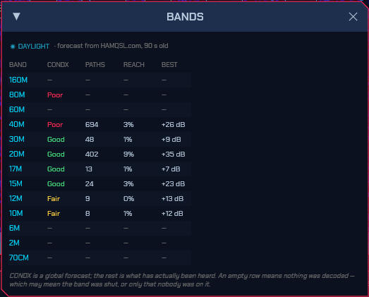
The propagation heat map answers “what has got
through”. The BANDS window (the BANDS button in the System box) puts that
next to a second, different answer: the calculated band conditions published
by N0NBH at hamqsl.com, which are a forecast from the
solar indices rather than a measurement of anything.
| Column | What it is |
|---|---|
CONDX |
The published verdict — Good, Fair or Poor — for this band, for whichever half of the day it is at your QTH |
WSPR |
Global WSPR activity on the band over the last 15 minutes, from wspr.live: how many reception reports the world’s WSPR network produced. A measurement that needs nobody at your receiver. Shown brighter the busier the band is; hover for the report, transmitter and receiver counts |
PSK |
The same figure for the activity modes, from PSK Reporter: FT8, FT4 and the CW/RTTY reporting that WSPR’s beacons do not cover, including the freeband reporters on 11 m. Same shape, same brightening, same hover |
PATHS |
Decayed count of receptions in this band’s field: how much got through |
REACH |
Share of the world with evidence on it: how widely it got through |
BEST |
Best decode margin anywhere in the band, dB above the mode’s own floor |
PATHS and REACH are both there because either alone misleads: a contest
pile-up is a great many paths through one small piece of sky, and a band quietly
open everywhere is the reverse.
WSPR, PSK, PATHS and REACH are all measurements, but of different things:
WSPR is the whole world’s WSPR network, PSK is the activity modes from
PSK Reporter, and PATHS/REACH are what this station (and the Reverse Beacon
Network, when it is on) actually heard. WSPR and PSK are never blank merely
because your own antenna is deaf to the band.
The same verdicts colour the band buttons in the band/mode menu, so choosing a band shows its forecast where you are already looking. Green is Good, yellow Fair, pink Poor. Hovering gives the verdict in words along with its source.
Three things this deliberately does not do.
- Bands with no published verdict stay blank. The feed covers four groups —
80/40 m, 30/20 m, 17/15 m and 12/10 m — and nothing else. 160 m, 60 m and
every band above 10 m have no
CONDXand no button colour, and never will: filling them in from a neighbouring group would be inventing data. 60 m sits inside the published frequency range and is still not covered, and what opens the microwave bands — rain scatter, aircraft, the troposphere — is not something a solar-flux verdict knows anything about. - A band with no paths is not called closed. An empty row means nothing was decoded, which may mean the band was shut or only that nobody was on it. Those two look identical from here.
- The forecast is global, not yours. It is computed from the solar indices for the whole planet and says nothing about your antenna, your noise floor or any particular path. Where it and the measured columns disagree, the measurement is right.
Day or night is worked out from the Sun’s elevation at your own locator, so the correct half of the published table is read wherever you are.
Where the numbers come from. hamqsl.com, fetched in the background once an hour for as long as the program is running. This is the one exception to the rule that sdroxide’s space-weather requests happen only while the 3D view is open: the band menu is always there, so these have to be too. It stays one request an hour — the two share a cache, so with the 3D view open the second one comes back “not modified” — and hourly is the interval the publisher asks for.
The WSPR column is a second request, to the public wspr.live database, fetched every ten minutes for as long as the program is running. It asks for one thing — the reception-report count per band over the last fifteen minutes — and is cached on disk like the rest.
The PSK column is PSK Reporter’s receive-side: the reports in the same fifteen-minute window for 160 m through 10 m — and the 11 m citizens’ band, which wears the same code, so freeband FT8 is counted where the operator is actually working — one request every ten minutes, cached and interpreted exactly like the WSPR one. PSK Reporter asks its clients to query no more than once every few minutes, so ten is comfortably inside it.
The document is cached on disk, so the last verdicts are on screen immediately at startup and survive being offline. Everywhere they appear they are labelled with their age.
Meteor showers
At the foot of the BANDS window is the one propagation forecast that has nothing to do with the ionosphere: the annual meteor showers currently active, from the International Meteor Organization’s working list. A shower’s window and its radiant are fixed, so nothing here is fetched — it is a table and a clock.
Each active shower shows its name and IMO code, its peak ZHR (the meteors an observer would see with the radiant overhead under a perfect sky — a brightness, not a count to expect), a green PEAK on the peak date, and whether the radiant is above your horizon right now, with its altitude and compass bearing from your locator. Hover a row for the parent body and the geocentric velocity.
The radiant’s altitude is the part that changes: a shower is worth listening for when its radiant is up, because a radiant below the horizon sends its trails up through the Earth. A fast shower (above about 40 km/s) leaves longer-lived ionised trails, which is what makes meteor scatter work on 6 m and 2 m and what gives the brief 10 m and 11 m openings their seconds-long returns.
The dates are the shower’s published activity window, not a fitted rate curve: inside the window the rate is the peak figure, outside it there is nothing.
IBP beacons
Below the showers is the NCDXF/IARU International Beacon Project — eighteen beacons on five bands, on a schedule that is entirely deterministic: a three-minute cycle of eighteen ten-second slots, aligned to UTC midnight, in which exactly one beacon is transmitting on each band at any instant. Nothing is fetched here either.
Each band’s row shows the metre band, the frequency, the callsign now transmitting, its location, and the compass bearing and distance from your own locator. The header counts down to the next beacon, and the whole list refreshes every second, so it stays live while the window is open. A beacon you can hear is a path that is open, measured rather than forecast — and the 10 m beacon at 28.200 MHz is the closest amateur-band proxy there is for 11 m conditions, which is why it is worth watching from a CB or SWL station.
Every beacon, whatever its proper name, works every band once per cycle: at the start of a cycle the 20 m beacon is the first in the list and the higher bands are showing beacons that started three, six, nine and twelve seconds earlier.
2.16 Satellite operation (SAT)
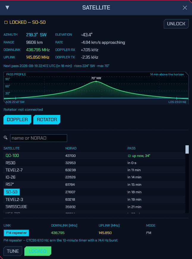
The SAT button in the System box opens the satellite window: pick a bird, lock on, and every voice and digital mode works through it with Doppler corrected continuously. The button glows green while a lock is running, because the correction keeps being applied whether or not the window is open.
The window has three tabs. SATELLITES is the picker and the live lock described below. PASSES lists every pass over the next 24 h or 48 h, soonest first, from every satellite with frequencies on file (tick all satellites for the whole list, which takes longer to search): when it rises in UTC and local time, how long until then, how long it lasts, how high it peaks, and which way it rises and sets. PEAK ≥ hides the low ones — 10° by default. Click a row to pick that satellite on the SATELLITES tab, with its pass diagram and links. QO-100 is the beacon calibration (2.22) — a geostationary bird needs no Doppler, but it does need its LNB offset measured, and that is the whole of working it. Either tab carries a dot while its own work is running, and the SAT button glows for both.
And a locked satellite labels your panadapter. With a lock running, the satellite’s downlink transponder segments are drawn along the frequency scale with their own labels — “CW beacon” as a mark, “linear transponder” as a bounded span — so a passband reads as where the CW segment ends and the SSB begins instead of an unexplained slab. They move with the Doppler correction, so they stay on the signals they name. Only downlinks: a transponder’s uplink is on another band, and a label here for it would point at a frequency you are not listening to. If you have your own frequency table for a bird it wins over the built-in one, as it does everywhere else.
The picker lists every satellite the station tracks — the amateur group
subscription, anything you pasted into the TLE tab
(6.10), and the curated set — with
a search box and, once your grid locator is set, live elevation and the next
pass for each. Pass times are worked out in UTC and shown in UTC with your
own local time beside them (13:08 UTC (14:08 local)). Pick one and its
published links appear: transponders,
repeaters, beacons, each with its passbands and mode, inverting transponders
marked inv. TUNE just sets the dial and mode to the link, nothing more.
LOCK ON is the mode itself. An SSTV link — the ISS lists both its 70 cm
(437.550 MHz) and 2 m (145.800 MHz) SSTV downlinks — tunes and locks in
SSTV FM, so the picture is decoded with the Doppler corrected.
What a lock does. The engine — not the screen — propagates the orbit with SGP4 a few times a second and:
- Corrects receive Doppler in the DSP. The dial and the waterfall stay on the published frequency; the receiver quietly follows the moving signal. A NOAA APT pass, which sweeps several kilohertz, holds still on the waterfall while the correction readout sweeps instead — through zero exactly at closest approach.
- Derives your uplink from the transponder. Tune anywhere in the downlink passband and the transmit frequency follows the published mapping — reversed across an inverting transponder, with the sideband flipped for SSB, fixed for an FM bird. Split and VFO B are ignored while locked; XIT still works as a manual trim on the mapped uplink.
- Pre-corrects transmit Doppler, and keeps correcting during the over — the shift rides the transmitted IQ, so a long SSB over or an FT8 burst stays on frequency at the satellite from key-down to key-up.
- Steers the antenna, if a rotator is configured (2.16.1): tracks above your horizon, swings onto the rise azimuth in the last minute before AOS, parks after LOS.
The window shows it all live: azimuth and elevation with a compass point, range and range rate, both corrections in hertz, the nominal downlink and the computed uplink, and the pass in progress or the next one. Locks survive stale elements gracefully — corrections are suspended (never frozen) and resume by themselves when a TLE refresh brings a fresher set.
The 3D view joins in: the locked bird is highlighted with a line drawn from your QTH to it — the sightline your antenna points along — and with AUTO the camera flies to frame you and the satellite together and holds the shot through the pass. The pass window there gets a LOCK ON button of its own, so a satellite found by searching the globe is one click from being operated.
QO-100 and anything else behind a converter. The dial is the published frequency throughout, so a station hearing the 10 GHz downlink through an LNB sets that LNB as its Converter offset and locks on exactly as it would on a low-orbit bird — the transponder mapping then derives the 2.4 GHz uplink from wherever the dial sits. What it also needs is the Transmit row beside that offset (6.2) set to what is in the transmit line, or transmit stays switched off: for the usual QO-100 station that is its own offset, of nought.
Locking needs your grid locator (Settings ▸ General) and current element sets (Settings ▸ TLE). On a CAT rig the lock still tracks, predicts and steers the rotator, but Doppler stays uncorrected — riding a serial dial a few times a second is not something most rigs enjoy; an IQ front end does it for free in the DDC. And if satellite software is steering the dial through the built-in rigctld server at the same time, the window warns you: two Doppler corrections is one too many.
2.16.1 Rotator control
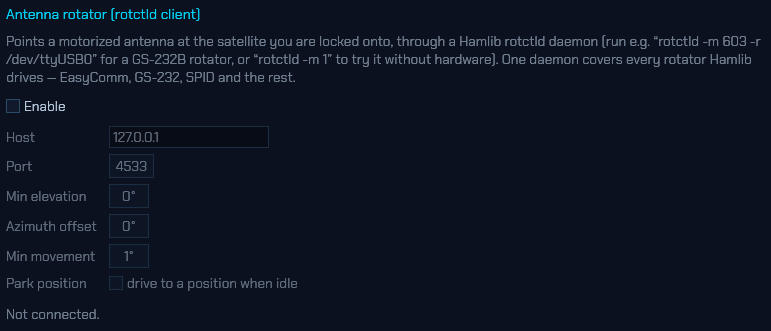
sdroxide points motorized antennas two ways, chosen in Settings ▸ Servers.
A Hamlib rotctld daemon (the default) — run it next to the hardware:
rotctld -m 603 -r /dev/ttyUSB0    # a Yaesu GS-232B interface
rotctld -m 202 -r /dev/ttyUSB0    # an EasyComm II controller (SatNOGS-style)
rotctld -m 1                      # Hamlib's dummy rotator, for trying it out
One daemon reaches everything Hamlib drives — GS-232, EasyComm, SPID, AlfaSpid and the rest — so this is the route to reach for first.
A controller on a serial port directly — EasyComm II or Yaesu GS-232A/B, for
a station that would rather not run a daemon. Pick the connection, then the
port (e.g. /dev/ttyUSB0) and baud (9600 on most controllers). These land the
same commands the daemon would and are offered for convenience; the rotctld
route above is the one exercised here, so treat the serial paths as not yet
proven against real hardware.
The shared settings are a minimum elevation below which the rotator parks (set it to your local roofline), an azimuth offset for a rotator whose north is off, the smallest movement worth commanding (motors last longer not chasing tenths of a degree), and an optional park position.
The ROTATOR window — open it from 🪟 WINDOWS ▸ Antenna rotator (or Settings ▸ UI) — is the manual side. A compass shows the hardware’s own reported bearing against the one you have asked for; drag or click the dial to point, type a bearing, or pick a DX country and the beam swings to its bearing from your own locator. STOP halts where the antenna is, PARK drives to the park bearing, and AUTO hands the antenna back to the satellite lock. While the satellite lock is steering, a manual point takes over and the lock will not drag the beam off it — re-affirm the lock (AUTO, or its ROTATOR switch) to hand it back.
You can also point the beam from where you are working. On the FT8/FT4 map a right-click aims the antenna at that spot; a decode row’s BEAM chip (on the station card) aims it at the station’s locator. Both need a rotator configured and your grid locator set.
PSTRotator works too: choose it under Program, with the host it runs on and its UDP control port (12000 unless you changed it). In PSTRotator, turn on UDP Control in Setup. sdroxide takes over from PSTRotator’s own tracking when it starts pointing, and asks where the antenna is once a second; PSTRotator answers on the next port up (12001), which must be free on the machine sdroxide runs on. Until it answers the status line says so — PSTRotator stays silent while it has no controller connected — but the pointing commands still go out.
2.17 Running more than one radio
SDR Oxide can run several radios at once — an HF transceiver and a VHF dongle, a network rig at the station and an RTL-SDR on the desk, or two receivers inside the same box. Each radio is complete and independent: its own interface, its own tuning, mode and band, its own panadapter and waterfall, its own receive audio, its own sub-receiver, digital modes and scanner. They appear as tabs, and with a single radio configured — the way every installation starts — the tab strip stays out of the way entirely and the window looks exactly as it always has.
Adding a radio. Open Settings → Radio. Across the top of the tab is a row of buttons, one per radio, ending in +. Press + and a new radio is created and focused, with the dialog already open on its (empty) Radio tab. A new radio deliberately starts with no interface — silent, rather than grabbing the first device it finds, which is usually the device another radio is already using. Pick its interface, configure it, press Apply / reconnect, and it is on the air. From then on the same strip appears across the top of the main window as well.
While a station somewhere else is also open in a tab (8.2), the same + asks where first: On this computer, or On that station. The two are as different as plugging a dongle in here and plugging one in at the remote site — one radio appears in this machine’s roster, the other in that station’s, where its engine runs and where its settings are saved. A radio added on a station comes back as a tab of its own within a second or so, with the Radio page already open on it, exactly as a local one does. The + on the main window’s tab strip always means this computer; the choice lives in Settings → Radio, which is where the two rosters are side by side.
The + only acts on the press when the radio is going on the computer you are sitting at. Where it would go on a station instead — which is always the case in the browser client (8), since a browser has no hardware of its own — it names the station and asks first. Creating a radio is not something to do to somebody else’s machine by accident: it opens a configuration there and starts an engine, and everyone else connected to that station gets a tab for it.
Rearranging the strip. The buttons in Settings → Radio can be dragged into any order you like: pick one up, and a cyan caret shows where it will land. The main window’s tab strip follows the same order, and it is remembered between sessions. A short drag that never really moves is still a click, so switching radios costs exactly what it did before.
What the order does not change is which radio is the station’s first. That one holds the shared network services, takes the command line’s settings and the configuration paths every earlier version used, and is the one radio that cannot be closed — wherever on the strip you put it. Connections to other stations can be dragged about too, but they are in no roster here, so they come back at the end of the strip next time.
Adding somebody else’s station. A radio in a tab does not have to be attached to this machine. Settings → General takes the address of an sdroxide server and gives it a tab of its own, exactly like a local radio (8.2) — the engine stays where the antenna is, and what crosses the network is the spectrum, the audio and the commands. Such a tab is closed from the roster like any other, which hangs up and changes nothing on the server.
Closing a radio that lives on a station. Hanging up and closing a radio are different things, so the × on a connection’s button asks which you meant:
- Close this tab — hang up. The radio stays exactly where it is, and comes back the next time you connect to that station. This is what × on one of this computer’s radios does straight away, without a menu.
- Close it on station — take the radio out of that station’s roster. The same menu says what that means and you have to press again, because it reaches across the network.
Closing a radio on a station does what closing a local radio does here: the
roster entry goes, its configuration stays on that machine, its engine stops and
its device is released, and every client on that station — not just this one —
sees the radio leave. A station’s first radio is never offered: it runs the
station-wide services and answers at the plain /ws that every client arrives
at. A station that does not allow this at all — one whose sdroxide was not
started as a server, or an older one — offers only “Close this tab”.
Radios you did not mean to create live on the station, not on the screen that made them, so closing their tabs is not enough — they are announced again on the next connection. Close it on station is what removes them. If you want to know when they appeared, the server logs each one:
journalctl -u sdroxide | grep "radio added to the roster".
The tab strip. Each radio gets a tab of its own, and the open one is joined to the page below it. Click anywhere on a tab — not just its name — to switch to that radio; the small buttons a tab carries keep their own clicks. Everything else keeps running behind the radio you are looking at — audio keeps playing, digital modes keep decoding, skimmers keep skimming, the scanner keeps scanning. Besides its name, each tab carries:
- ● TX — this radio is transmitting. Visible from every tab on purpose: it is the one thing worth knowing about a radio you are not looking at.
- ⚠ — this radio has a problem (typically: its device is unreachable and it is retrying in the background).
- 🔊 / 🔇 — mute this radio’s speaker audio. Muting is only the speaker: decoding, skimming, recording and everything else continue, so a muted background radio still fills its FT8 list and still spots.
- ⊞ — open this radio in a split view of its own, or close the one it has (see below).
- LINK — open or close sdroxide’s link to this radio (see below). The chip is lit while the link is open, like every other chip in the program.
Closing a radio is deliberately not on the strip — that lives in Settings → Radio, behind a dialog rather than one stray click away.
Putting a radio down. A station does not always have every radio it is set up for plugged in. Each tab carries a LINK switch — lit while sdroxide’s link to that radio is open, dark when it is not — and pressing it changes that. With the link closed, the radio’s interface is closed with it: no device claimed, no CAT port held, no network rig dialled, and no reconnecting in the background. Everything it is configured as stays exactly where it is. The tab stays too, with its name greyed, and its whole Settings → Radio page is still there to be read and edited. Press the switch again and the radio opens where it left off.
It says LINK rather than on and off because it is sdroxide’s switch rather than the radio’s, and the difference matters on a station with more than one rig on it. On/off in sdroxide means one thing and one control: PWR, which throws the set’s own switch over the control link (2.7). What it lets go of is this end of the connection — the USB device, the serial CAT port, the LAN session — so sdroxide is demonstrably no longer holding that radio: the dongle can be unplugged, the port is free for another program, and the rig’s network session is hung up. A transceiver with a power switch of its own is not touched by it and stays on, receiving into its own speaker; sdroxide has no way to press that switch and, having pressed it, no way to press it back. What is guaranteed is the transmit side: a radio that is off has no transmitter as far as sdroxide is concerned, so nothing — not PTT, not TUNE, not a digital-mode sequence, not a program on its built-in server — can key it until it is switched back on. That is on top of the station-wide interlock below, which applies to every radio that is switched on.
The same switch is in the roster at the top of Settings → Radio, which is where the choice is easiest to see across all the radios at once — and on the main window itself, as the ⛓ link button above the A/B selector in the Frequency module (at the top of the VFO menu on a tablet- or phone-width layout), which switches whichever radio the pane it sits on is showing. All three are one switch: press any of them and the others follow. There are three because a single-radio station has neither a tab strip nor a roster switch — the button in the Frequency module is the only one it gets — while a station with several wants it on the strip, next to the radio it belongs to. It is remembered: a radio switched off is still switched off after a restart, and sdroxide never touches its device at start-up. That is what makes it the right place to leave the rig that is boxed for the summer, or the dongle somebody has borrowed — rather than deleting the radio and setting it up again later.
A radio that is switched off has no mute button (there is nothing coming out of it) and shows no ⚠: it is not reaching for a device and failing, it has been told not to reach. Its spectrum and waterfall hold the last picture they drew and stop scrolling — the waterfall’s vertical axis is time, and rows repeated while nothing is being received would be time that never happened. The first radio is not treated specially here — the station’s own radio can be switched off like any other, and its shared services keep running. One tab has no switch: a receiver lent out as another radio’s panadapter, whose front end is the borrower’s to hold. With a single radio the strip stays out of the way entirely and the Settings roster offers no switch — the Frequency module’s power button is then the one place the radio is switched off and back on.
A radio at a station. The switch works the same way over a connection, from a native remote client and from the browser client alike: pressing it asks the station to switch that radio, and what comes back is the station’s answer — so the button shows where the switch really stands, not what this screen asked for a moment ago. Everyone connected sees it move, including whoever is sitting at the station. This is how a headless station’s radio is put down at all: with no screen of its own, the browser is the only place its switch exists. A station running an older sdroxide than this screen offers no switch, and none is drawn rather than one that would be quietly ignored.
Split view. The ⊞ toggle gives a radio a pane of its own: toggle it on a second radio and the main area splits into two equal columns, side by side; a third radio makes three. Every pane carries its own copy of the radio strip, so any pane can be switched to any radio that is not already on screen — a radio is never shown twice, and its name is greyed out in the other panes’ strips while it is up. Keyboard shortcuts and MIDI go to one pane at a time: the one whose open tab carries the accent outline, and clicking anywhere in a pane moves them there. Close the split views (or their radios) and the last pane left takes the whole window back.
Naming. A tab names itself after its radio’s interface — PlutoSDR, TCI, HPSDR — so a strip full of different hardware needs no housekeeping to be readable. To name one yourself, use the Name box under the button row in Settings → Radio; clear the box and the tab goes back to naming itself.
The first radio is the station. The first tab is where the shared, station-level things live: the spot feeds (DX cluster, POTA, SOTA, PSK Reporter, FreeDV Reporter), WSPRnet, TLE refresh and the antenna rotator all run on it, because a station has one of each of those no matter how many radios it has. Its configuration also lives where a single-radio installation keeps it, so adding and removing other radios never touches it. It is the one tab that cannot be closed. The spots it collects are shown on every radio’s waterfall and SPOTS list, not only its own (issue #410).
One transmitter on the air at a time. The radios share a station-wide transmit interlock. Keying any radio — PTT, TUNE, a digital-mode sequence, the voice keyer, or a program connected to one radio’s built-in server — claims it; while it is held, a key-up on any other radio is refused with a notice naming the radio that is on the air, and nothing on the refused radio changes state. The interlock releases on unkey.
What is shared and what is per-radio. Memory channels, memory folders, band stacks, the digital-mode operator settings (callsign, grid, templates), the saved profiles (6.12), the logbook, spots and awards belong to the operator, and are shared: save a memory on one radio and it appears on the others. The dial, mode, filter, session restore, scanner setup and the built-in servers (TCI, rigctld, WSJT-X) belong to each radio. Each radio’s servers have their own configuration precisely so two radios can serve two copies of WSJT-X on two ports — which also means an additional radio’s TCI server starts disabled, because the default port would collide with the first radio’s; enable it and pick a free port in §6.8.2.
Background tabs. A hidden radio’s waterfall freezes — the pixels are only drawn for the tab you are watching — and resumes with a clean gap when you switch back; the spectrum data underneath it never stops. Keyboard shortcuts and MIDI controls go to the focused tab only.
Closing a radio. The × beside the radio’s name in Settings → Radio shuts the radio down and removes it from the strip. Its configuration directory is kept on disk — a closed tab is not a request to destroy the configuration behind it — but a radio added later starts fresh rather than inheriting it.
Several receivers from one box. Some hardware carries more than one receiver on a single connection, and each of those receivers can be a radio tab of its own. Configure two radios with the same address and they share the connection rather than fighting over it — closing either tab leaves the other streaming, and the transmitter belongs to the first receiver’s radio:
- TCI — a rig with two receivers (a SunSDR2DX) serves one radio on RX1 and another on RX2, independently tunable, from one WebSocket. See §6.2.4.
- HPSDR Protocol 2 — the board’s DDCs are independently tunable receivers; run one radio per DDC on different bands from one Ethernet connection. (Protocol 1 boards have a single receiver.) See §6.2.3.
- PlutoSDR — a 2R2T-capable board (a Pluto+, or a rev. C unlocked to two channels) serves a second radio from its second receive chain. The AD9361’s chains share one local oscillator, so this is a second antenna on the same spectrum — retune either radio and both move. See §6.2.7.
One radio can receive for another. A transceiver with no wideband output — a CAT rig on a sound card — can borrow another radio’s receiver and use it as its panadapter, on the same antenna or fed from the rig’s I.F. socket. The two then behave as one radio: the spectrum, the waterfall and the sub receiver come from the receiver, the dial, the mode and the transmitter stay with the transceiver, and you can listen to whichever of the two you prefer. A radio that has been lent out this way leaves the tab strip — its front end belongs to the radio that borrowed it — and stays in the roster in Settings → Radio, marked 🔗, which is where it is configured and where the pairing is undone. See §6.2.15.
A server serves every radio in the roster, each on an address of its own —
--server brings up the same radios the GUI would (8.1).
A native client that dials such a station gets all of its radios as tabs,
the same as if they were plugged into this machine
(8.2) — one connection per radio,
made for you. That is the same mechanism that lets one screen hold this
machine’s radios and somebody else’s at the same time. A browser tab holds one
radio at a time and picks it with ?radio=<id> (9.1).
2.18 Repeater operation (DUPLEX and TONE)
A repeater listens on one frequency and answers on another, so working one means transmitting where you are not listening — and usually proving who you are on the way in, with a sub-audible tone under the voice or a whistle at the start of the over. Both live in the DUPLEX and TONE buttons in the VFO/RIT module, beside split, RIT and XIT: the other three things that decide where this station transmits relative to where it listens.
Everything here is per radio and is remembered across a restart, and a memory channel stores the whole set-up with the frequency (2.12).
The shift — DUPLEX
Press DUPLEX for the shift controls.
- SIMPLEX / − / + — which side of the dial to transmit on. The offset magnitude is kept when you go back to simplex, so switching a repeater off and on again does not cost the figure you set for it.
- Offset — how far, in kHz. Whole kilohertz for anything published; the field takes a shift to the hertz for a machine that needs one.
- AUTO — take the shift from the band plan as you tune. It only speaks inside a repeater output sub-band: everywhere else it leaves the radio simplex, so the calling channels stay simplex. Touching the direction or the offset by hand switches AUTO off, because otherwise the next turn of the dial would put it straight back.
Underneath, the popup shows the receive and transmit frequencies as they now stand. The DUPLEX button lights amber whenever the two differ, and the panadapter draws the transmit frequency the way it draws XIT — a marker line and a labelled bracket when it is on screen, and just the label when it is not, which on 70 cm (a 7.6 MHz shift in Region 1) it never is.
NOTE: The built-in shifts are transcribed from published band plans and have not been checked against a repeater. They cover the sub-bands whose shift is settled across a whole region — 10 m, 6 m and 4 m in Region 1, 2 m and 70 cm in all three (in Regions 2 and 3 alike, outputs above 147 MHz take their inputs 600 kHz up), 1.25 m and 33 cm in Region 2, 23 cm — and say nothing anywhere else, deliberately: a missing entry leaves you simplex, which is obvious the moment nobody comes back, while a wrong one transmits confidently onto somebody else’s channel. Set the region under Settings → General (6.1), and set the shift by hand wherever your local plan differs.
On a CAT-controlled rig, sdroxide owns the shift. These controls work by moving the radio’s dial for the length of the over — the same way RIT, XIT and split do on a rig whose VFO is its whole frequency control — so the radio’s own duplex setting has to be off, or the two would be added together and the over would go out a shift away from where you asked for it. sdroxide therefore puts an Icom back to simplex whenever the dial moves — on HF once per band, and on VHF and up every time the dial moves at all, including into the transmit frequency at the start of an over.
That matters on a radio that puts a duplex setting back by itself. An IC-9700 remembers one per band, so switching to 70 cm or 23 cm recalls whatever that band was last left on, normally DUP−; and the auto-repeater function fitted to several regional versions arms on the frequency, so simply tuning from one 2 m channel to the next puts a shift back without ever crossing a band edge. Set the shift here rather than on the radio; the radio’s own DUP button will be overridden the next time the dial moves.
The tone — TONE
Press TONE for what goes out under the voice, the 1750 Hz burst, and the receive tone squelch — the three things a repeater directory’s one line about tones actually asks for.
- OFF / CTCSS / DCS, then the tone or the code. CTCSS is the 50-entry standard table; DCS is the 104 standard codes in either polarity (NORMAL / INVERT).
- 1750 Hz burst — EVERY OVER opens each transmission with it, and SEND sends one now. Pressed while you are transmitting it plays over the microphone; pressed on receive it keys the transmitter, sends the burst and lets go again, which is what the burst button on a European mobile does. The length is next to it (100–2000 ms; 500 is a good default). It is also an action — 1750 Hz tone burst — so it can go on a key, a mouse button, a MIDI pad or a footswitch (6.4).
- Receive tone squelch — the same control as the tone button in the receiver module (2.7), with a MATCH TX shortcut that arms on receive whatever this station transmits.
The sub-audible tone is sent on NFM only — it is a slice of an FM channel’s deviation budget and means nothing on a sideband — and the transmitted voice is high-passed and trimmed while it is on, so an over with a tone under it occupies the same channel width as one without. The settings can be arranged in any mode; they simply take effect when you are in FM.
NOTE: On a radio that modulates its own audio — a CAT rig fed through its microphone or data input, or a TCI rig — a sub-audible tone has to survive that input’s own high-pass filter, and most microphone inputs are built to keep exactly this sort of thing out. sdroxide sends it regardless, because where the input passes it (a data or line input, or a rig fed at baseband) it works. If the repeater will not open, use the rig’s own CTCSS encoder, set at the radio. The 1750 Hz burst is in-band and passes either way.
NOTE: DCS is a data stream rather than a tone, and the bit order it is encoded with here is transcribed from the standard rather than measured against a repeater — the same ambiguity that stops the decoder naming which of the 104 codes a signal carries (2.7). If a machine will not open on DCS, try the other polarity, and then CTCSS, which has no such ambiguity.
2.19 DRM (Digital Radio Mondiale)
DRM is digital shortwave broadcasting: a few hundred OFDM carriers filling 9 or 10 kHz, carrying AAC-coded audio together with the station’s name, a scrolling text message and the broadcaster’s clock. Where a shortwave AM signal fades into mush, DRM either arrives as clean audio or does not arrive at all.
It is a broadcast mode, so it works like WFM rather than like the digital
modes in section 3: there is nothing to transmit, no QSO to sequence and no
transcript. Select DRM on the MODE button and listen.
Tuning. Put the dial on the channel centre, not on one edge and not on a sideband. DRM’s carriers sit symmetrically around the frequency the broadcaster publishes, so the published figure is the number to dial. The passband shading shows the default 10 kHz channel; the filter presets offer the six widths the standard allows (4.5, 5, 9, 10, 18 and 20 kHz), which affect what the display shades and what the S-meter reads — the decoder reads the real width out of the transmission itself and does not need to be told.
It is not instant. DRM spreads each frame over 400 ms or two full seconds before transmitting it, and the receiver has to collect all of that before it can decode any of it. Expect a few seconds between landing on a signal and hearing anything, and a second or two of standing delay after that. Nothing here reacts the way an AM signal does, and that is the transmission rather than the radio.
The DRM window (the DRM button, 2.7) is what to read while tuning one in. Across the top is a row of indicators for the stages of the decode, in the order they lock:
| Stage | What it means |
|---|---|
| IO | Samples are reaching the decoder. |
| TIME | Symbol timing has been recovered. |
| FRAME | Transmission frames have been found. |
| FAC | The Fast Access Channel decoded — the transmission has said what it is. |
| SDC | The Service Description Channel decoded — it has said what its services are. |
| AUDIO | Audio frames are decoding. |
They fill in left to right, and where they stop is the diagnosis. Nothing lit
at all means no signal on this frequency. TIME and FRAME lit with FAC dark
usually means the signal is there but too weak or too distorted to read — DRM
needs a genuinely clean channel, and about 15 dB SNR for a reliable 10 kHz
decode. Everything lit except AUDIO means the multiplex is being read but its
audio is not decoding, which usually means a signal too intermittent to carry
audio through even though the control channels are getting through. If instead
the DRM window says the codec is not decodable, that is a different problem
with a fix — see Codecs below.
Below the indicators, once the signal is locked:
- SNR and MER — how good the channel is. MER is the honest one for a digital signal: it measures how tightly the received constellation sits on its ideal points.
- MODE — the robustness mode (A to D) and the channel width. A is for a ground-wave path and carries the most data; D is for a badly scattered sky-wave one and carries the least. Most international broadcasts are B.
- INTERLEAVE — 400 ms or 2 s, the trade the broadcaster made between riding out deep fades and being quick to acquire.
- PROTECTION — the error-protection levels of the multiplex’s two parts.
- OFFSET — residual sample-clock error against the transmitter. A large, steady figure means your receiver’s reference is off rather than anything being wrong with the broadcast.
- DOPPLER / DELAY — how fast the path is moving and how far apart its echoes arrive, when the channel estimator has enough to say. High Doppler on a long-haul path is what robustness modes C and D exist for.
Then the service itself: the station’s name, its country and language codes, the codec, the bit rate — typically 8 to 25 kbit/s, which is why DRM sounds like speech radio rather than like FM — and whether it is mono or stereo. Underneath is the text message the audio stream carries, which broadcasters use for the programme name, a website or a contact address, and the broadcaster’s own clock where the multiplex carries one.
More than one service. A few multiplexes carry two programmes, or a programme alongside a data service. When they do, a row of numbered buttons appears; click one to decode that service instead. Most broadcasts carry one and the row does not appear.
QUALITY plots SNR and MER over the last minute. Two traces on one scale, because the gap between them is the reading: SNR is what the receiver measures of the channel, MER what the demodulator actually achieved on it. On a clean path they track each other. MER falling away from SNR means something the noise figure does not describe — multipath, a drifting transmitter, an overloaded front end — is costing the decoder margin, and that is a different problem from a weak signal. The trace restarts rather than joining across a dropout, so a gap in it is a real loss of sync and not a slow patch.
CONSTELLATION is the picture of how well the signal is being decoded, as opposed to whether it is. It plots the equalised symbols of one of the three logical channels — FAC, SDC or MSC, chosen with the buttons — against faint rings marking where an ideal symbol would land. The MSC is the one to watch: it carries the programme, and it uses the densest constellation, so it runs out of margin first.
Read it by shape:
- Tight clusters on the rings — margin in hand. Points are drawn green when they sit comfortably inside their own decision region, amber as they approach the boundary, and red past it, where a symbol would have been read as its neighbour had the error correction not caught it. A signal that decodes cleanly is mostly green with a scattering of amber.
- Clouds grown until neighbours touch — the decoder is at its limit. This is what a rising error rate looks like before the audio starts breaking up, so it is the earliest warning you get that a station is about to go.
- A ring, or a cloud rotated off the rings — not a weak signal but an equaliser that has not resolved the channel’s phase. Check the tuning: a carrier well off the channel centre does this.
- A tight cloud in the middle only — nothing decoded yet.
The number of clusters is the constellation’s order, which the transmission chooses: 4-QAM is four, 16-QAM sixteen, 64-QAM the sixty-four you will usually see on the MSC. The FAC is always 4-QAM, because it has to be readable before anything has said what the rest of the multiplex uses.
The MSC carries a couple of thousand cells per frame; the plot shows 512 of them, taken evenly across the whole frame rather than from the front, so fading spread across the frame shows up rather than being cropped out. The decoder is only asked for them while the window is open — on a remote link that is a few hundred numbers several times a second, worth carrying while you are watching and pure waste when you are not.
Audio. The decoder’s output goes to the speaker in place of the demodulated signal, and the AGC is bypassed — what you hear is the level the broadcaster mixed, not a level the receiver invented. If a station is stereo, it is played in stereo.
Codecs. AAC is built in and needs nothing. xHE-AAC, which most of the surviving DRM30 broadcasters have moved to, is decoded through libfdk-aac if that library is on the system — it cannot be built in, because its licence and this program’s are incompatible, so it is looked up when the radio starts and used if it is there. Install it and restart:
| Debian / Ubuntu | sudo apt install libfdk-aac2 |
| Arch | sudo pacman -S libfdk-aac |
| macOS | brew install fdk-aac |
| Windows | put libfdk-aac-2.dll beside sdroxide.exe |
Opus is not part of the DRM standard — it is an extension a few experimental transmissions use — and decodes if libopus is installed, the same way.
When a station’s codec cannot be decoded, the DRM window says so in place of guesswork: the codec is named, followed by not decodable, and the panel tells you which library is missing. The DRM button in the top bar stays dark in that state, because nothing is being heard.
What is not here. Transmit: DRM is a broadcast system and there is no amateur DRM to send. Journaline, MOT slideshows and the electronic programme guide are carried by the standard but not shown. The CELP and HVXC speech codecs of the original standard were withdrawn from it and nothing transmits them.
2.20 HD Radio (NRSC-5)
HD Radio is the digital sidecar of an FM broadcast: a set of OFDM carriers placed in the spectrum on either side of the ordinary analog FM carrier, about 20 dB below it in power. They carry HDC-coded audio together with the station’s own name, a slogan and a short message. Most digital FM stations in the United States and Mexico transmit it, and a hybrid station sounds better on the digital side than on the analog one — provided it can be heard at all, because the sidebands are far weaker than the carrier they share.
Select HD RADIO on the MODE button and listen. It is a broadcast mode, like WFM and DRM: there is nothing to transmit and no transcript. The panel is receive-only.
It needs nrsc5 installed. The decoder is libnrsc5, from the
nrsc5 project, and sdroxide does not
include it: HD Radio’s audio codec is proprietary, so the library is looked for
on the computer the radio runs on when sdroxide starts, and used if it is there.
Without it HD RADIO stays on the MODE button but greyed out — hover it
for the reason — and the keyboard’s next/previous-mode keys step past it. On
Arch it is the nrsc5-git AUR package; elsewhere it is usually built from the
nrsc5 source, whose sudo make install puts it in /usr/local/lib, where
sdroxide looks. On Windows, put libnrsc5.dll and the DLLs it needs beside
sdroxide.exe; anywhere, libnrsc5 beside the executable is found, and the
SDROXIDE_NRSC5_LIB environment variable names a library in any other place.
Restart sdroxide after installing it — the library is looked for once, at
startup. With a remote client it is the station’s computer that needs it, not
the one the client runs on.
An nrsc5 built without its audio decoder (-DUSE_FAAD2=OFF, which a
distribution unwilling to ship the patched codec might do) can find a station
and read its name but never play it. sdroxide notices after a couple of seconds
of locked signal with no audio at all, stops decoding, and the HD Radio window
says so.
Tuning. Put the dial on the analog carrier’s centre, the same number you would use for plain WFM. Unlike DRM, the digital carriers are not centred on that frequency but spread out around it — roughly 129 to 198 kHz either side — so the front end has to capture a span of at least about ±200 kHz to see them at all. A complex sample rate of 1 Msps or more is ample. Below 400 kHz the decoder is not started at all — both sidebands cannot fit, so it could never lock — and the window says so, naming the rate this receiver delivers; that is also what a CAT rig handing over demodulated audio gets. The default passband is ±200 kHz, which is the channel the sidebands occupy, and there are no filter presets — the decoder reads the real channel out of the transmission.
It is not instant. The decoder needs a few seconds on a clean signal to find the OFDM frame and get the audio stream running, and it holds a fraction of a second of delay after that. A station that is perfectly listenable in analog WFM can still be too noisy for the digital side: front-end overload and strong neighbours on the FM band are the usual reasons. A band-notch filter is another — a wideband receiver with its FM broadcast notch engaged is deaf across 88–108 MHz, so a bad CBER can be a front-end setting rather than the decoder.
The HD Radio window (the HD button, 2.7) is what to read while tuning one in. Across the top are two indicators for the stages of the decode, in the order they lock:
| Stage | What it means |
|---|---|
| SYNC | The OFDM frame is being read. |
| AUDIO | The selected programme’s audio is decoding — not the silence the decoder fills a lost or failed packet with. |
Sync without audio is a real state — the frame is locked but the programme’s audio is not coming through, often because the signal is marginal — so the HD chip in the top bar lights only when audio is actually decoding.
Below the indicators, once the signal is locked:
- MER L / MER U — the modulation error ratio of the lower and upper digital sidebands separately. These are the honest read on the signal: they fall well before the audio does. The two being far apart means one side of the channel is being lost — a selective fade, a tilted antenna, or a strong neighbour near one edge — rather than the signal simply being weak.
- CBER — the channel bit-error ratio after the inner code. Below about
1e-3the outer code can correct it; above that the audio starts to break up. - OFFSET — residual carrier frequency error. A large, steady figure means your receiver’s reference is off rather than anything being wrong with the broadcast.
- PSMI — which of the FM hybrid service modes the station is transmitting.
Then the station’s own text: its name, its slogan, and a message it is currently airing. If the multiplex carries more than one programme — HD-1 and an HD-2 subchannel, say — a row of HD-n chips lets you pick which to hear. Tuning to another station puts it back on HD-1.
The audio is stereo (HDC carries two channels) and plays as two; a mono transmission simply has equal channels, so it sounds the same.
The decoding itself runs on a thread of its own, so it does not hold up the panadapter or any other decoder on the same receiver; a machine too slow to keep up with it loses samples and re-acquires rather than stalling the radio.
What is not here. Transmit: HD Radio is a broadcast system. HD on the AM band (medium wave) is not wired up yet; this build decodes the FM hybrid only. The album art and programme-service data (track titles) the multiplex can carry are not shown, and the receiver does not blend back to analog when the digital side drops — the mode decodes the digital side or is silent.
2.21 Recording the audio and the spectrum
REC, in the receiver box beside MUTE, opens a small picker with the two things that can be recorded — and they are different things, so either or both may run:
- MP3 — what you hear and what you send, described in the rest of this section.
- I/Q WAV — the raw spectrum the receiver is delivering, described under Recording the spectrum below.
The button lights while either is running and hovering it names the files. On a narrow window the whole receiver box folds into the RX menu chip, and there the same two rows are at the bottom of that menu, under Record audio and Record spectrum, rather than behind a button of their own. It has no keyboard shortcut by default, but Record on/off is in the bindable action list, so it can be put on a key, a mouse button or a MIDI pad (6.4).
What goes into it. On receive, the audio at the end of the receive chain — past the AGC, the noise blanker, the auto-notch and noise reduction — but taken before the volume control and MUTE. Turning the AF down, muting the receiver, or a spoken announcement ducking the speakers changes what you hear and nothing about the file, and the sub receiver’s own volume and mute are equally invisible to it. What you were listening to is what gets archived, at the level the receiver delivered it. The squelch is the one control that does reach the recording: what a closed squelch silences is recorded as silence. Where a mode replaces what you hear rather than filtering it — decoded FreeDV/RADE speech, or a voice-keyer message you are monitoring — the recording follows the speaker.
On transmit, it takes the audio sdroxide sends: the microphone after mic gain and the transmit EQ, with any CTCSS tone or 1750 Hz burst that goes under it; a digital mode’s burst; the CW keyer’s sidetone; and, for a tune-up, a 1 kHz tone at the tune level standing in for the unmodulated carrier — without which the file would go quiet for the tune and drift out of step with real time, a little further with every one. Receive is held out of the recording for the length of the over, so a full-duplex radio hearing its own signal cannot land on top of your voice. One kind of over leaves no trace: CW handed to the radio’s own keyer travels as text over the CAT link (6.2), and text has no audio to record.
The two channels. The recording is stereo unless you ask otherwise, and what is in the two channels depends on whether anything is running that needs them apart:
- A second receiver (SUB), or a stereo broadcast (WFM or DRM), is using the right channel. The recording is then genuinely split — the main receiver in the left channel, the sub or the stereo difference in the right — and your own transmitted audio goes to the right channel alone, so the two ends of the QSO can be separated afterwards.
- Nothing is using it — the ordinary case, and always the case on a CAT radio with its audio on a sound card, which has one receiver and no sub. There is then nothing to keep apart, so both what you receive and what you send are written to both channels and the file plays centred instead of out of one ear.
MONO, beside MP3 in the picker, writes a single channel instead, with receive and transmit taking turns on it: a smaller file, and the honest format for a recording that is going to be played back in mono anyway.
Either way the layout is settled when the recording starts — which is why MONO is greyed out while a recording runs. A file already being written keeps the channel count it began with, so switching the sub receiver on, or a broadcast’s stereo pilot coming and going, cannot change it halfway through.
Where it goes. Recordings land in <Music>/sdroxide/ (or
~/.config/sdroxide-brown/recordings on a platform with no music folder) — or wherever
Settings → General → Recordings → CHOOSE… points; DEFAULT puts it back.
The setting is a path on the machine the radio is attached to, so a remote client
sets it on the station rather than on its own laptop. Files are named for when
they started and what the radio was doing:
sdroxide_2026-08-23_14-32-05Z_14.074000MHz_USB.mp3
— the UTC date and time, then the dial frequency and mode at the moment you
pressed REC. Tuning or changing mode later does not rename the file. All radios
share the one folder, so the second and later radios of a multi-radio session
put their number in the name (sdroxide_radio1_…); recording is per radio, and
each tab has its own REC writing its own file.
The file is 48 kHz MP3 at 192 kbps, encoded on a thread of its own so that neither the encoder nor the disk can interrupt the audio. If the disk does stall for longer than the few seconds of slack in front of it, the recording takes a clean gap rather than a stutter stitched out of whatever fitted.
Started from a remote or browser client, a recording is written on the machine the radio is on — the server’s music folder, not yours (8). REC needs an audio output to tap: with none configured it says so rather than recording silence. It stops by itself if the audio output device is changed under it, and one still running when you quit is closed properly, so there is never a half-written file to repair.
Auto-record. The Auto-record row of the picker follows the receiver’s squelch and gives each transmission its own file: a recording starts when the squelch opens, and closes after the number of seconds of silence you pick — 2 s, 3 s, 5 s, 10 s, or off. A monitoring session then becomes one stamped file per transmission rather than a single file that grows all afternoon through the gaps. It follows its own radio, so a monitor left on a tab behind another keeps splitting its files while you are watching something else. The squelch is what defines silence here, so the chips are only offered when one is set; with the squelch wide open there is nothing to follow and the row says so. It is a session setting like Stop after, not a stored preference, and arming one clears the other — they are two answers to when a recording ends. Turning Auto-record off, though, clears neither: a Stop after timer you set and can watch counting down is left to run, and a quick clip already asked for is left to finish. Choosing none of them is not choosing the other. It needs a front end whose squelch the program itself applies (an SDR); a CAT radio’s squelch belongs to the radio and its meters carry no passband level to follow, so the row says that rather than arming a recorder that would never close. The REC chip shows the difference: armed but waiting is a steady red outline, while a file actually being written fills the chip red and the fill breathes.
Quick clip. The Quick clip row is for a short sample rather than a session: press 30 s or 1 min and the recording starts by itself and stops at the end of that span — small enough to attach to a reception report, with no second press to stop it. Pressing the lit clip again starts the span over. The Stop after row below is the other way to end a recording — 15 through 90 min, or no stop, with a countdown beside the chips — and a clip, a timer and the Auto-record row are three answers to when a recording ends, so arming any one clears the others. All are session settings, not stored preferences.
Recording the spectrum
I/Q WAV, the second row of the REC picker, records the whole span the receiver is delivering rather than the audio of one signal in it: a band you can replay afterwards and tune around inside, decode differently, or hand to someone else. Beside the button is what it costs at the current sample rate before you start it, and the megabytes and minutes written once it is running.
The file is a stereo 32-bit float WAV — I in the left channel, Q in the right —
at the receiver’s own sample rate, which is what SDR#, SDRuno,
HDSDR, SDRangel and GNU Radio all read. The centre frequency travels
both in the name and in the file’s auxi chunk, because those are the two
places those programs look, so a capture opens tuned to where it was made:
SDRoxide_20260829_134507Z_14074000Hz_2400000sps_IQ.wav
It also plays back here, with nothing to type — sdroxide --file <capture>
takes the rate and the frequency out of the header. --rate and --freq still
win if you give them.
It is large: eight bytes a sample. At 2.4 Msps that is 19 MB a second, a gigabyte a minute. A WAV’s sizes are 32-bit and so stop at 4 GB — three and a half minutes at that rate — so a capture that outgrows one is written as RF64 instead, which every program above opens. Nothing to choose: the file is an ordinary WAV until it needs not to be.
A radio that hands over demodulated audio rather than I/Q — a transceiver on a sound card — has no spectrum to record. Started from a remote or browser client the capture is written on the machine the receiver is plugged into, for the same reason the MP3 is, and rather more urgently: a gigabyte a minute is not something to send over a link.
This is the same data --record-iq (12) writes,
in a container other programs can open — --record-iq writes the bare samples
and starts with the program, which is what a headless capture wants.
Playing a recording back into the decoders
The MP3 is not only an archive. ▶ RECORDINGS…, at the bottom of the REC picker under Play back, opens the PLAYBACK window: the files in the recordings folder, newest first, each read by what its name records — the time, the frequency and the mode — rather than by its file name. Press ▶ PLAY on one and it goes back through the decoders as though it were on the air: the SSTV picture that was missed paints again line by line, CW, RTTY, PSK, Olivia, FT8 and every other mode that decodes from audio decode it afresh, and the waterfall and the decode log fill as they did at the time.
What happens when it plays:
- The radio stands down. For the length of the playback the file is the radio — it takes the path a sound-card radio’s audio takes — and the transmitter is out of reach. A strip above the waterfall says ▶ PLAYBACK — not live for as long as it lasts, so a recording is never taken for the band.
- The dial and the mode go to what the file’s name records, so the right decoder is listening. Change the mode while it plays to try the recording in another decoder; click on the waterfall to put a decoder’s tones where the signal is, exactly as on a sound-card radio.
- The transport: ⏸ PAUSE / ▶ PLAY, ↺ AGAIN back to the start, LOOP to go round instead of stopping at the end, and the seek bar to go to any point in the file. Paused, the decoders hear silence.
-
■ STOP puts the radio back on the dial and in the mode it was left in.
- CLEAR beside ▶ PLAY deletes a recording from the folder for good. The first press turns it into DELETE? and only a second press on the same row deletes, so a stray click costs nothing. The file playing back and one still being recorded cannot be deleted until they stop.
A stereo recording plays back in stereo: a WFM stereo broadcast comes back with
its two channels, and ST lights while it does. ST still forces mono, and
noise reduction or the auto-notch take it back to mono, exactly as on the air.
The decoders always take the left channel — the receiver; on a recording made
while transmitting, the right is your own transmit. Playback reads the recorder’s MP3 and also WAV, OGG
Vorbis and FLAC made elsewhere: copy one into the recordings folder and it is in
the list. A file whose name carries no stamp plays in the mode you are in. An
I/Q capture is listed but cannot be played here — it is spectrum, not audio, and
plays with --file. A recording is played where the receiver is: from a
browser, the list is the station’s recordings folder and the engine opens the
file there.
This is a replay of the demodulated audio, not of the band: the frequency offset, the passband and the demodulator were fixed when the recording was made. To tune around inside a recording afterwards, record the spectrum instead.
2.22 QO-100 beacon plugin
The QO-100 (Es’hail-2) narrowband transponder carries a beacon on its lower edge, at 10489.750 MHz, transmitted as 400 baud Manchester BPSK. Every ground station receives it through an LNB whose local oscillator is only roughly on frequency and drifts with temperature — so the dial and the signal disagree by a few kHz, and by different amounts on a cold morning and a warm afternoon. The QO-100 tab of the SAT window (2.16) measures exactly where the beacon really is, corrects the converter/LNB offset so the dial and the signal agree, and then keeps correcting it as the LNB drifts. It lives in the SAT window because QO-100 is a satellite — a geostationary one, which is why it needs no Doppler correction and why keeping its LNB calibrated is the whole of working it.
Everything runs off the raw IQ the hardware is already delivering, so the main dial is never moved and the plugin keeps working with the receiver parked anywhere the beacon is still inside the captured span.
Note: like the skimmers and the ISM decoder, this is a wideband feature. It needs a true IQ source and is unavailable when a CAT radio is feeding demodulated audio.
For a task-oriented walkthrough of getting a Pluto + LNB station onto QO-100 from scratch, see the QO-100 quick-start guide (Türkçe); this section is the reference detail behind its beacon-sync step.
How it works: ON and AUTO
- ON starts the spectral tracker. Once a second it looks in the shaded park lane of the strip for the beacon’s give-away shape — two symmetric lobes with a null between them — and works out where the carrier sits and how far that is from 10489.750 MHz. It reads the beacon’s shape, never its bits, so it keeps a measurement even where the telemetry will not decode. Nothing is changed yet: ON only measures.
-
AUTO closes the loop. With it lit, every clean, steady measurement the tracker makes is applied — a slow, deadbanded, rate-limited nudge to the converter/LNB offset that pulls the beacon back onto 10489.750 MHz and holds it there as the LNB warms up and drifts. A single noisy reading never yanks the receiver; it takes a run of agreeing measurements to move the offset, and no correction is ever made while you are transmitting — each one reopens the receiver, and on a station whose transmitter and receiver are the same box that would cut you off mid-over. A correction held back for an over goes out as soon as it ends.
AUTO also watches its own work, and switches itself off if the offset it writes does not move the beacon, or if it has moved the offset further than any LNB could plausibly be out by. You get a notice saying which. The usual cause of the first is a transverter row covering 10489.750 MHz on a station that also has one: the row’s offset is the one the dial uses, so that is the one AUTO and APPLY correct — if you have edited the single converter offset by hand and nothing changed, that is why.
-
TELEMETRY (optional) additionally runs the AO-40 frame decoders, with a
carrier → sync → CRCreadout of how far each pass got. It is an independent check and shows the beacon’s own status text when it locks; it is not needed for calibration.The beacon alternates two frame formats and sdroxide reads both. The uncoded frame is 514 bytes behind a sync word and a CRC, and it either checks out or it does not — which on a station with a phase-noisy LNB usually means it does not, because a CRC over 514 bytes wants a nearly perfect bit stream. The coded frame carries 256 bytes behind Reed-Solomon and convolutional coding, interleaving and a distributed sync vector, and still decodes with roughly one channel symbol in twelve arriving wrong. If telemetry appears on your station at all, that is usually the one bringing it.
Behind both is a tracking receiver — a frequency-locked loop on the carrier, a matched filter on the chips, and a timing loop on the chip clock — so a drifting LNB is followed rather than searched for. It locks frequency and not phase deliberately: the beacon is differentially encoded, so absolute phase carries nothing, and a phase-locked loop would spend its life fighting LNB phase noise for a quantity nothing needs.
Recommended procedure
- Get the beacon roughly onto frequency first. In Settings ▸ Radio, set the converter/LNB offset for your own LNB and get it as close as you can, so the beacon lands somewhere near 10489.750 MHz on the dial. The plugin corrects a residual error of a few kHz to tens of kHz — not a wild guess.
- Open the SAT window and switch to the QO-100 tab.
- Press ON. For a fast first approach, step the width value at the top
(
−/+, in ±5 kHz clicks up to ±50 kHz) until you can clearly see the beacon’s two lobes in the strip. Widen only as far as you need to find it. - Double-click the middle of the beacon in the strip. That plants a “the beacon is here” mark — the two lobes with the null between them, centred on the null. Then press APPLY CORRECTION at the bottom. The receiver reopens on the corrected offset and the beacon jumps toward the centre.
- Narrow the width back down (toward ±5 kHz), double-click the middle of the beacon once more to centre it precisely, and APPLY CORRECTION again. Two passes — a coarse one wide, a fine one narrow — get it within a few hundred Hz.
- Press AUTO. From now on the offset is corrected continuously as the LNB drifts. You can shrink the window to the corner and leave it running in the background — the correction keeps going with the window closed, and the SAT chip stays lit and the QO-100 tab keeps its dot while it does.
The panel
┌─ SAT ─────────────────────────────────────────────────────────┐
│  [ SATELLITES • ]  [ QO-100 • ]                               │
│                                                               │
│  [ ON ]  [ TELEMETRY ]  [ AUTO ]     width [−] ±25 kHz [+]     │
│  park [lo −][lo +] +5 … +20 kHz [hi −][hi +]                   │
│  ┌─────────────────────────────────────────────────────────┐  │
│  │  mini waterfall — shaded = park lane,                    │  │
│  │  dashed line = 10489.750 MHz target,                     │  │
│  │  double-click the beacon's centre to mark it             │  │
│  └─────────────────────────────────────────────────────────┘  │
│  searching / locked — N blocks tried, M locked                │
│                                                               │
│  TRACKER   +1.2 kHz   (null 12 dB  sym 0.94  snr 15 dB)       │
│  DRIFT     -6 Hz/s  -0.4 Hz/s²                                 │
│  AUTO      -3.19 kHz over 4 corrections   last +80 Hz (7s)     │
│  RECEIVER  10489.750000 MHz                                    │
│  TARGET    10489.750000 MHz                                    │
│  MEASURED  10489.751200 MHz  (tracker)                        │
│  DRIFT     +1.2 kHz                                            │
│  CONVERTER OFFSET  -9749920000 Hz                             │
│  DECODE    ● carrier  ○ sync  ○ CRC    sync 4/32 err ×0       │
│  TELEMETRY <beacon status text, when the decoder locks>       │
│                                                               │
│                 [  APPLY CORRECTION  ]                         │
└───────────────────────────────────────────────────────────────┘
- ON / OFF — start or stop the spectral tracker (see above). Greyed out only when the receiver’s configuration says 10489.750 MHz is unreachable — usually because no converter/LNB offset has been set up yet (Settings ▸ Radio ▸ Converter). If the current capture simply does not reach the beacon, a Tune to 10489.750 MHz button appears.
- width
−/+— how far either side of 10489.750 MHz the AO-40 decoder searches, ±5 kHz to ±50 kHz in 5 kHz steps. Wider costs a wider capture and a slower sweep, so open it only as far as needed to find the beacon, then bring it back to ±5 kHz. At the widest setting, with TELEMETRY on and no decode, the decoder is the most expensive thing in the program — still comfortably inside the window it is searching, but a noticeable fraction of one core. It does not affect the spectral tracker, which uses the park window instead and costs almost nothing at any setting. - park
lo/hi— the lane, in +kHz above the dial, that the spectral tracker scans for the twin-lobe shape (shaded on the strip). Park the beacon inside it, clear of the DC spike, before switching ON. With AUTO armed the tracker also reaches down toward the centre so it can follow the beacon there after the loop has corrected it. - mini waterfall — the slice of spectrum around the beacon, with the target line and, once the decoder locks, the measured frequency marked. Purely a picture: if the receiver is on another band the strip is blank but the plugin keeps working. Double-click it to hand-mark the beacon for APPLY.
- TRACKER / SHAPE — where the tracker puts the carrier, and how convincing
the shape was (
nulldepth, lobesymmetry,snr). - DRIFT — the LNB’s measured drift rate, and its curvature as it warms.
- AUTO — a running total of what the closed loop has corrected, and when it last acted.
- RECEIVER / TARGET / MEASURED / DRIFT — the dial now, the 10489.750 MHz target, where the beacon was actually found (from a decoder lock or your hand-mark), and the difference. DRIFT is green within ±200 Hz, amber to ±3 kHz.
- CONVERTER OFFSET — the converter/LNB offset currently in force at the beacon, and the number APPLY and AUTO write to. On a station with a transverter row covering 10489.750 MHz that is the row’s own offset, not the single converter offset behind it — the same precedence the dial follows.
- DECODE — the AO-40 decoder’s progress:
carrier → sync → CRC, plussync N/32 err ×M(fewest sync-word bit errors, and how many candidate frame alignments were seen —×0near the error budget means no real frame, just a chance hit). - TELEMETRY — the beacon’s own decoded status text. A valid CRC with garbled text is a warning no number above would catch.
- The status line under the strip is the honest “attempted vs. succeeded” count, like the ISM decoder’s bursts/decoded line.
APPLY CORRECTION
APPLY CORRECTION writes the corrected converter offset and reopens the receiver — the same brief interruption Settings ▸ Radio ▸ Apply makes. It uses whichever measurement is current: a decoder lock if the telemetry decoded, otherwise the beacon mark you double-clicked on the strip. From a decoder lock it stays disabled until there have been two locks and the latest carried telemetry text — a 32-bit sync within three bit errors plus a 16-bit CRC pass by pure chance roughly once every couple of hours, and one lock is not enough to change a setting on. After it acts, the window shows what changed and when.
Once AUTO is armed you rarely touch APPLY again — it is the manual path for the first coarse/fine passes, and for stations where the telemetry never decodes and the twin-lobe shape is all you have.
Remote and browser clients
The plugin runs on the machine the radio is on. Its readout is not sent to remote or browser clients yet, so on those the window opens, the strip draws from the shared spectrum, and the status line says the readout is local to the receiving station.
3. Digital modes
sdroxide has several families of digital mode. What they all share — how a mode is entered, the calling-frequency buttons, and the bands with more than one agreed frequency — is in 3.1. FT8, FT4 and FT2 are automatic, timeslot-based modes with QSO sequencing, a world map, and automatic logging; they and the logbook they write into — which also serves every other mode and your manual QSOs — are 3.2. PSK31, RTTY, Olivia, THOR and FSQ are live keyboard modes: you tune onto a signal, read the decoded text, and type a reply that transmits as you go (3.3–3.4). Hellschreiber is a facsimile mode with no decoder at all — it paints letters onto a scrolling strip and you read them by eye (3.5). SSTV is an image mode: received pictures build up in a gallery and you transmit composed images (3.6). RIFP carries pictures as numbered, checksummed packets over its own FSK modem rather than as an analogue scan, and is the one mode here that is not single sideband (3.7). Weather fax receives the charts the meteorological services broadcast on short wave, and transmits nothing (3.8). JS8 uses FT8’s waveform but carries a conversation instead of a contest exchange (3.9). RF Paint is a transmit-only mode that draws text and pictures directly onto the far station’s waterfall (3.10). WSPR is not a QSO mode at all — it is a beacon that measures propagation, and what it produces is a list of paths rather than contacts (3.11).
3.1 General considerations
On 11 m, where the family is worked on the citizens’ band rather than an amateur allocation, the FT8/FT4/FT2 (and JS8) exchange follows WSJT-CB’s conventions instead — grid-less, one call at a time, its own hashed pairs and free-text reports — see 3.2.9.
Every digital mode is entered the same way: open the Band/Mode popup and choose the mode from the DIGITAL row. The panadapter locks to the digital sub-band (the audio range just above the dial), and the mode’s operating panel appears in the lower part of the window; a draggable divider sets how much height the panel gets.
While in a digital mode the BAND row of the Band/Mode popup doubles as a frequency picker. Bands where the mode has a standard calling frequency carry a cyan underline: clicking one jumps the dial straight to that frequency, staying in the mode, and the button highlights when the dial is already on it. Every band is available in every mode — clicking a band without an underline jumps to that band’s default frequency, also staying in the mode, and you tune from there. Where a mode’s convention differs by region — PSK31 and RTTY on 40 m, SSTV on 80 m and 40 m — the button uses the one for the IARU region set on the General tab (6.1).
Two more things hold across the modes. Your callsign and grid are one identity for the whole program: the General settings tab and the FT8/FT4/FT2 setup window (3.2.1) edit the same values, and they fill the keyboard modes’ CQ macros, the FT8/FT4/FT2 exchange, and everything the station reports or uploads. And every digital transmission goes through the normal transmit path, so the ham-band lockout and the usual transmit safety apply in every mode.
Setting your transmit level
On a radio that modulates the audio you hand it — a CAT rig on its sound card, a FLEX, an Icom on its network port — Drive is not the audio control. It reaches the radio’s power register, and a data signal that is overdriving the transmitter will go on overdriving it wherever Drive sits. The control you want is TX audio, in the transmit module in place of the Mic rail (2.10), and the adjustment is: bring it down until the rig’s ALC is barely moving, then set the power at the radio.
Each mode remembers its own level, saved as you set it, because FT8, RTTY,
PSK and MCW do not load a transmitter the same way. A mode you have never set
starts from the level for the carrier it goes out on — sideband for most modes,
FM for VHF packet, APRS and RIFP, where the same control is the deviation
instead. All of it lives in digi.json
(13).
Choosing a slotted mode tunes the radio
FT8, FT4, FT2, JS8 and WSPR are worked on one dial frequency per band, in lockstep with everyone else on it — a receiver a few kilohertz off is not off-centre, it is deaf — and each of them keeps its own. On 20 m that is 14.074, 14.080, 14.084, 14.078 and 14.095600 respectively, so even arriving from the mode next door is a move. Picking one of them from the DIGITAL menu therefore tunes the dial to that band’s agreed frequency, the same way APRS, ADS-B, VDL2 and AIS already do (3.12, 3.13, 3.15, 3.16).
SSTV and SSTV-FM are in this group too. They are worked on one agreed frequency per band for the same reason, and each keeps its own: 14.230 on 20 m, and on 11 m the community’s 27.700. So choosing SSTV moves the dial just as choosing FT8 does (3.6).
It moves the dial only when it has to, and only inside the band you are already on:
- already on one of that mode’s own frequencies? Left alone. The DXpedition (Fox/Hound) window you deliberately tuned survives the mode change, and so does any move you make once you are in the mode.
- the band has no convention for the mode? Left alone — 60 m for FT8, or anywhere off the amateur bands. The rule puts you on the right spot in the band you are on; it does not decide which band you wanted. Press a band button first.
- recalling a memory or a band-stack entry? Left alone. Those carry a frequency of their own and it wins, so a memory stored on an off-plan FT8 net comes back on the frequency you stored it with.
- already in the mode, and you pick it again? Not a change, so nothing moves. Standing in SSTV and pressing the chip again does not retune under you.
Every other mode leaves the dial exactly where you put it. PSK31, RTTY, Olivia, THOR and the rest are worked across a sub-band rather than on one spot, so a frequency you chose inside it is a frequency you meant. The button below is how those reach a convention — by asking.
The agreed frequencies for a mode, and your own
Every digital mode carries a ⇵ button in its operating panel. It lists every band’s agreed frequency for that mode — FT8, FT4, FT2, JS8, WSPR, PSK, RTTY, FSQ, SSTV (analog and FM), RIFP and APRS all have one — grouped by band with the band you are already in at the top, so changing band is one click rather than a band button and then a number you had to remember.
Several bands have more than one entry, and that is where the list earns its place twice over:
| Mode | Where it happens |
|---|---|
| FT8 | The DXpedition (Fox/Hound) window on every HF band, 6 m’s second frequency at 50.323, 23 cm’s 1296.500 for where 1296.174 is unusable, and 13 cm’s two narrow-band segments (2320.174 and 2304.174) |
| RTTY | The DX calling spots (3.590, 14.083) |
| SSTV | The move-up-when-busy secondaries — a picture takes two minutes, so one frequency per band is occupied most of the time |
The button’s face is the frequency you are on when the dial is already sitting on one of them, and reads ⇵ FREQ when it is not. Clicking a frequency moves the dial; where you sit inside the audio passband is a separate control and is left alone.
WEFAX has its own STATIONS button instead (3.8): its transmitters are not on any band plan, so they are listed by station rather than by band.
Saving your own. The bottom of the list has + Save this MHz, which remembers the dial you are on under the mode you are in. The club net that meets on 3.585 every Tuesday is not in anybody’s global table and never will be, so having found it once you should not have to find it again. Saved entries appear in the same list marked with a ★, in every band group like any other, and carry an ✕ to forget them — published conventions do not, because 14.074 is not this station’s to delete.
A mode the tables have nothing at all for — Olivia, THOR, Contestia, Hellschreiber — still has the button, with nothing in it but the save row. That is the only way the first entry for such a mode could ever be made.
Your saved frequencies belong to the station, not to the screen: they live in
digi_presets.json beside the band plan (13), every
radio at the station offers the same ones, and a remote client draws the same
list the console does. They are also deliberately passive — the band buttons
and the “choosing a slotted mode tunes the radio” rule above both stay on the
published calling frequency, because those move the dial without being asked and
one station’s own note is not where the band is worked. Being on a saved
frequency is enough to stop the mode rule moving you off it.
The frequencies that differ by region — PSK31 and RTTY on 40 m, SSTV on 80 m and 40 m — are not offered as a choice, because the IARU region setting (6.1) already says which one applies to you. Set that and the list is your region’s.
An entry shown in amber is one your region’s band plan does not put narrow data on. That is not a mistake in the list: the WSJT-X DXpedition frequencies and the FSQCall set are global conventions built around the Region 2 band plan, and a few of them land in Region 1’s CW or phone segments (1.845, 3.567 and 24.911 for FT8 — of which only 3.567 and 24.911 are still amber in Region 2, where the top of each band is an all-modes segment). The DX will be there and so will everyone chasing it — but check your own band plan before you key, because sdroxide will not stop you.
Saving what a panel has decoded
The text and message panels carry a SAVE chip, next to CLEAR RX where the panel has one. It writes what the panel holds to a file, through the same save dialog the logbook and the ADIF export use, and the suggested file name carries the mode. With nothing decoded yet the chip is greyed out rather than saving an empty file. What goes in the file depends on the mode:
| Panel | What is saved |
|---|---|
| CW and the keyboard modes (RTTY, PSK, Olivia, THOR, …) | The receive text as it stands, as a .txt file |
| FSQ | One line per message: whether it was for you, sender, addressee and text. FSQ messages carry no time, so there is no time column |
| ACARS, packet, JS8 and APRS | A .csv file, one row per message or frame, with its UTC time |
| NAVTEX, VDL2 and HFDL | A tab-separated .txt file, one line per message, with its UTC time |
| WSPR and PI4 | The reception list as a .csv file, in the RECEPTIONS header |
| The CW/RTTY skimmer | Its spot list, from the Spots row of the skimmer’s settings |
The FT8/FT4/FT2 decode list has its own CSV and ADIF buttons instead (3.2.2).
3.2 FT8, FT4 and FT2
FT8, FT4 and FT2 are the automatic modes: timeslot-based, with QSO sequencing, a world map, a transcript, and automatic logging. Choose one from the DIGITAL menu (3.1) and the operating panel appears in the lower part of the window.
Choosing one also puts the dial on that band’s agreed frequency — 14.074, 14.080 and 14.084 on 20 m — because these are worked on one spot per band and a receiver anywhere else decodes nothing. When it does that and when it leaves your dial alone is in 3.1.
The three are the same protocol at three speeds — same message format, same error-correcting code, same panel, same logbook. Only the clock and the bandwidth differ:
| FT8 | FT4 | FT2 | |
|---|---|---|---|
| Slot | 15 s | 7.5 s | 3.75 s |
| Transmission | 12.6 s | 5.0 s | 2.5 s |
| Tones | 8 | 4 | 4 |
| Bandwidth | 50 Hz | 83 Hz | 167 Hz |
| Decodes down to | about −21 dB | about −17 dB | about −14 dB |
FT2 is the newest and the fastest — a complete contact takes about six seconds, and sixteen slots go by every minute. It buys that speed with sensitivity and with spectrum: each signal is twice as wide as an FT4 one and needs roughly 3 dB more of it, so it is a strong-signal mode for open bands and contests rather than a replacement for FT8. It also asks more of your clock: with 24 ms symbols, timing that would pass unnoticed on FT8 will cost you decodes (3.2.3).
WARNING — the clock that counts is the one decoding. FT8, FT4 and FT2 cut the audio into fixed periods by the clock of the machine running the decoder. On a station reached remotely (
--server, a browser, the native client) that is the server, not your phone or your PC. If the server’s clock is a couple of seconds out, nothing decodes at all: the waterfall is full of signals, the audio sounds perfect, a phone app held to the speaker decodes the same audio — and sdroxide’s list stays empty, with no error in the log. TheDTfigure on the station card cannot warn you either, because it is measured from decodes and there are none.Check it on the server before anything else:
timedatectlIt must read
System clock synchronized: yesandNTP service: active. A minimal Linux install (a bare Debian server, for example) may have no time service at all —NTP service: n/a. Install one and switch it on:apt install systemd-timesyncd timedatectl set-ntp true systemctl restart sdroxideDecodes appear within a minute or two. See also Troubleshooting.
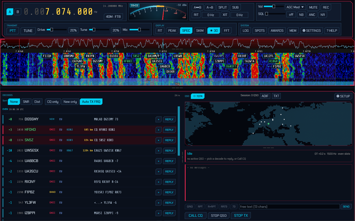
3.2.1 One-time setup: your callsign and grid
Click SETUP in the QSO area to open the FT8 / FT4 / FT2 Setup window:
- My callsign — your call (entered in upper case).
- My grid — your Maidenhead grid locator (for example
FN42). - TX period — whether you call CQ in the Even or Odd time slots. It sets the period you call in. Answering somebody instead takes the slot opposite the one they were last heard transmitting in, whichever that is; the readout beside your transmit offset says which period is actually in use.
- Auto-sequence — advance the QSO automatically (recommended on).
- Decode depth (FT8) — how hard the decoder digs for weak signals hidden under stronger ones. The quick single pass is always shown first, so a reply is never held up; Normal and Deep then add a signal-subtraction pass whose extra decodes appear one by one as it finds them, up to a second or so later on a fast machine. Fast skips it, Deep (the default) finds the most. On a machine too slow to finish a Deep pass before the next slot is ready, the slower passes of a slot are skipped while a newer one waits, so the list never falls further behind than one pass — choose Normal if that happens often.
- TX watchdog / Give up after — how long unattended transmitting may continue with no progress, and how many unanswered calls to one station are worth making. Both 0 to disable.
- Contest — the special operating activity, if any: None or EU VHF Contest (see Contest operation). Serial is the number the next exchange will carry.
- DXpedition — which side of an FT8 or FT2 pile-up you are on: Normal, Hound, or Fox (see DXpedition mode). Fox signals sets how many stations a Fox works at once. FT4 has no DXpedition layout, so the setting is ignored there.
- Message templates — the CQ / Grid / Report / R+Report / RR73 / 73 lines,
using the placeholders
{MYCALL},{MYGRID},{DX}, and{REPORT}. The defaults follow standard FT8 practice; you rarely need to change them.
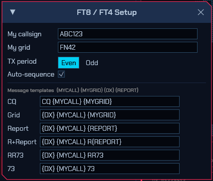
These settings are saved to digi.json (see configuration files).
3.2.2 The operating panel
Across the top is the slot bar — how far through the current turn the clock is. Dim cyan while receiving, pink while you are transmitting, with a mark where your burst stops and the turnaround begins. It fills once per slot: 15 s on FT8, 7.5 s on FT4, 3.75 s on FT2. When it reaches the end the decoder speaks and the next transmission may start, which is why it is worth a glance on a quiet band — an empty decode list under a bar that is still filling is a slot that has not finished yet. WSPR and JS8 have the same bar.
The panel has two halves:
- DECODES (left) — a live list of decoded stations. Each row shows the SNR
(colour-coded by strength), the audio frequency, the callsign, the country’s
flag, its continent, the grid, the distance, and the full message, with a
REPLY button on the right. Where the pane is wide enough the country is
named in full beside its flag; where it is not, hovering the row says it, and
a narrow pane moves it to the dim tail of the message line. The country comes
from the callsign rather than the grid, so it is there even for the decodes
that carry no locator, and the flags are built into the program — nothing is
fetched from the internet to draw them. CQ calls are highlighted. Decoded
stations are also marked as boxes on the waterfall.
The Sort buttons order the stations within each turn: SNR (strongest
first), Dist (farthest first) or Country (A to Z by DXCC entity, which
puts every station from the same country together). Pressing the active button
again reverses it — the arrow on the button says which way it is running — and
None returns to the order the decoder found them in. Turns stay in their
own blocks whichever sort is chosen; only the rows inside a turn move.
Single list dissolves the turn blocks: every decode goes into one list,
newest turn first, and the Sort buttons then order the whole list at once — the
band’s strongest signals or farthest DX in one sweep, whichever turn carried
them. The odd/even headers go with the blocks, so each row carries its slot
time instead, coloured by the slot’s parity (cyan for even, gold for odd) —
worth a glance before replying, since a sorted list puts decodes from several
turns ago next to fresh ones.
A CQ DX call only counts as a CQ for you when you actually are DX for the
caller — a different DXCC entity, or (when the prefix can’t be resolved)
3000 km or more away. Otherwise the row stays plain and the CQ only filter
skips it, so the list isn’t full of DX calls you shouldn’t answer. You can
still REPLY to such a station if you want to.
A badge after the callsign says what the station would be worth against your
log: DXCC (an entity you have never worked), BAND (worked before, but
not on this band), GRID (a new grid square), NEW (a callsign you have
never worked) or DUPE (already in the log for this band — the row fades
back). The New only filter keeps just the rows that would put something new
in the log.
Neither filter ever hides a message addressed to your own station: a station
calling you is not calling CQ, and may well be a dupe, but it is the one row
in the list you owe an answer to.
The − button at the right of a row mutes that station for the rest of the
session. It is the button for the station you have had enough of — a CB
frequency full of one machine, a pile-up calling the same station over and
over, the net you are not working — and it is drawn for any decode that names
a station, whether or not there is a sequencer behind the row, so a listener
watching a busy band can use it too. Once muted, that station’s new decodes
stop appearing anywhere: not as rows in the list, not as dots on the map,
not as paths on the propagation charts. It does not sound the audible alerts,
is not read out, and is never offered to AUTO as one to answer. Two things
it deliberately does not do: it sends nothing on the station’s behalf, and
it does not touch spotting or the online logbooks, so a station you have muted
is still uploaded if you work it by hand.
The list is memory only — there is no file and no saved copy, so closing
sdroxide brings every station back and nothing stays hidden because of
something pressed by accident one evening. That is also the fastest way out of
it. Within the session there are two more: press − again on the same
station’s row to unmute it, or press the N ignored · clear chip in the
DECODES header to unmute everyone at once. The chip only appears while
something is muted, and hovering it lists who. Rows already on screen when
you press − are dimmed and badged MUTED rather than vanishing —
enough to see that the press took, and the way to change your mind. They are
the only thing left of that station, and nothing new arrives to replace them,
so they fade out of the list by themselves. You can still tune to a dimmed
row and still REPLY to it: muting is about what interrupts you, not about
refusing to answer.
Changing band empties the list, along with the callsign boxes on the
waterfall, the dots on the world map and any stations you had marked to work.
A decode records the audio tone it arrived on and nothing about the dial, so
once you have moved there is no way to tell a row heard here from one heard on
the band you left — and those rows are not just text: clicking one sets your
transmit frequency from it and marking one queues a call at that offset. The
test is the band, not how far you tuned, so moving between the FT8 and FT4
slots, or into a DXpedition window, keeps the list. A QSY made on the radio’s
own dial counts exactly as one made here. WSPR is the exception — it surveys
several bands on purpose and its spots each carry the frequency they were
heard on, so its list keeps building across a hop.
CLEAR RX empties the list by hand, for when the band has gone quiet and
what is on screen is a list of stations that were there. Nothing on the air
stops, and the next slot starts filling it again.
CSV and ADIF in the DECODES header save the list as it stands — the
last 200 decodes — for a listener who has heard stations but worked none, so
the logbook’s own exports have nothing to write (issue #433). The frequency
of each row is the dial it was heard on plus its audio tone, so a row keeps
its frequency after a move within the band. CSV is one row per decode, for
a spreadsheet. ADIF is one record per station heard, marked
SWLso a logger — sdroxide’s own IMPORT included — takes it as a received report rather than a contact, with no report sent or received; a decode that names no sender (free text, a hashed call not yet resolved) has no call to log and is left out. Saving decoded text. Every text mode’s panel carries a SAVE chip beside its CLEAR RX (issue #533): CW and the keyboard modes write the receive text as it stands, and the message modes — ACARS, DSC, NAVTEX, VDL2, HFDL, FSQ, UVPacket, packet, JS8 and APRS — write their log, one line per message with the UTC time. WSPR, PI4 and the skimmer write their spot lists. The suggested name carries the mode, and the dialog is the same one the logbook and the ADIF export use, so the file lands wherever you choose. A mode with nothing decoded yet greys the chip rather than opening an empty file. - QSO (right) — a ⇵ frequency button listing every band’s agreed FT8/FT4
frequency (3.1), a world map
(your location, the station you are working, and
a transmit indicator — see the world map below), a station card showing the current step
(
Idle,Wait CQ,Calling CQ,Tx Grid,Tx Report,Tx R+Report,Tx RR73,Tx 73,Confirming,Done), and a transcript of the exchange (outgoing lines in gold, incoming in green, plus the queued next message).
Beyond the everyday exchange, the decode list understands the other FT8 message
layouts: compound and non-standard callsigns (DL/W1AW, W1AW/P), hashed
callsigns (shown as <W1AW> once that station has been heard, and as <...>
until then), free text (13 characters, listed as TEXT since it names no
sender), contest exchanges (EU VHF, ARRL RTTY Roundup, Field Day) and
DXpedition messages. Transmitting works the same way round: a message that the standard
layout can’t carry is sent in the layout that can, and the transcript records
what actually went on the air — addressing a compound call sends your own
callsign hashed (DL/W1AW <AB1CD> RR73), which drops the signal report, and
free text is cut to 13 characters.
The world map
The map in the QSO pane — and the one on the WSPR and APRS panels, which is the same map — is drawn as a dot matrix over the same coastline data the 3D globe is textured with, so a grid square lands on the same shoreline in both views. On the ground it draws:
- coastlines, from a 1/23° land map — about five kilometres. The shore is placed inside a cell rather than snapped to the grid, so it stays a clean curve rather than a staircase however far you zoom in;
- international borders, which is usually the fastest way to read where a station is — a prefix and a country outline answer the same question;
- rivers, drawn brighter the bigger Natural Earth ranks each one, so the Amazon and the Danube read as rivers while a creek in Siberia stays a hairline — and only the big ones survive a whole-world view;
- cities, biggest first, as many as the map has room for, with their names where a name fits. Zooming in shrinks the view faster than it runs out of cities, so smaller places arrive on their own as you go in.
The borders and rivers are drawn from the geometry they were surveyed as, not from a picture of it, so they are one dot wide at every zoom — a frontier stays a hairline in the right place whether the map is showing a hemisphere or a valley, instead of swelling into a band as you go in.
NIGHT, beside PROP above the map, shades the side of the Earth where the Sun is down, with the twilight between as a graded band, so the grey line shows on the map. Low bands go long and high bands close on the night side, and the terminator itself is where DX often turns up. It follows the clock, not the decodes, so it works with nothing heard yet; it is off by default and is the same switch on the FT8/FT4/FT2 and WSPR maps. The shade darkens land and sea alike, while the cities and the station marks stay on top of it at full strength. On a light theme it is lighter, because there the station marks are dark and would vanish into a dark night.
Drag (or one finger) to pan, wheel or pinch to zoom about the pointer, and double-click to hand the view back to the auto-fit.
3.2.3 Working stations
- Answer a call: click REPLY on a decode. sdroxide adopts that station,
takes the time slot opposite theirs, and runs the exchange automatically. The
slot is chosen from when that station was actually last heard transmitting —
not from the period the clock happens to be in when you press the button — so
answering a row from several turns ago still lands clear of them, and a
station that keeps an unusual sequence is answered in their gap rather than on
top of them. If they have been calling you, the reply opens where their
exchange actually stands rather than at the top: somebody repeating
<you> <them> -19gets your R+report back, not your grid, and the report they sent is already in the log entry. So a station who calls again after you pressed STOP QSO — or who called while you were busy with someone else — is answered with one press. - Losing a pile-up: if the station you called comes back to someone else
instead, sdroxide stops calling and holds at
Wait CQrather than doubling into their QSO. The transcript shows a pink line — “W9XYZ is working K1ABC” — so it’s clear they aren’t talking to you, and calling resumes automatically when they call CQ again (or come back to you). The hold gives up after five minutes. A 73 / RR73 you already owe still goes out, so a finished contact is never dropped unlogged. - Call CQ: click CALL CQ. When several stations come back in the same slot, sdroxide picks which to work first rather than taking whichever decoded first: a station already worked this session goes last, among signals of similar strength a new DXCC entity wins, and otherwise the strongest does — it is the one most likely to complete. The others are listed in the transcript (“also calling: …”) so you can work them next. An answer that isn’t a grid is still an answer: a station that comes back with a signal report (many do, and one that already knows your grid always will) puts you on the answering side of the exchange — R+report next — instead of leaving you calling CQ over the top of them. A late 73 from the contact you just finished is not a caller and is not adopted as one.
- Set your transmit tone: click a decode row (or click a station box on the waterfall) to set your transmit audio frequency to that station’s frequency. The audio frequency is clamped to 200–3500 Hz.
- Pick the message yourself: the row under the transcript holds the five exchange messages — GRID, RPT, R+RPT, RR73, 73. Clicking one jumps the exchange to that message and the sequencer carries on from there, the way WSJT-X’s Tx1–Tx6 buttons do. The current step is highlighted, and the buttons are inactive until you are working someone.
- Send free text: type into the field beside those buttons and press SEND (or Enter). It goes out verbatim in the next transmit slot and then the exchange picks up exactly where it left off — a queued line never completes or logs a contact in place of your 73. FT8 carries 13 characters of free text, so that is what the field accepts.
- Stop: STOP QSO ends the current QSO gracefully; STOP TX aborts the current transmission immediately and un-keys.
- The list says where the band is open. Each decode carries its continent in its own colour, resolved from the callsign — so which way the band is running is legible down the column without reading a single callsign. Hover a row for the rest: DXCC entity, CQ and ITU zone, grid, distance and beam heading from your own grid, whether the station is new or already in your log and on which band, who a directed CQ is aimed at, and the raw signal report, frequency and DT.
-
Auto TX FRQ picks where you transmit. On by default (the button above the decode list, or the setup window). Answering on the frequency of the station you are calling looks right and isn’t: they transmit in the period opposite yours, so their frequency says nothing about who is transmitting there when you key — and whoever is will not hear you. Instead sdroxide picks the quietest spot in your own transmit period, from the stations it has decoded there, and moves no further than it has to. While it is on, clicking a decode or a station label on the waterfall no longer drags your transmit frequency onto that station; the click just selects. It has no effect in DXpedition mode, where both roles have their frequencies decided for them.
Turning it off does not hold the frequency. It chooses the other mover: with Auto off, answering a station jumps your transmit tone onto theirs. To pin the tone, use Hold TX below.
-
Hold TX frequency pins the transmit tone. Off by default (the setup window). With it on nothing moves the tone by itself: not answering a station, not the call queue walking on, not calling CQ, not a click on a decode or on the waterfall. It overrides Auto TX FRQ, and unlike WSJT-X’s Hold Tx Freq there is deliberately no modifier-key escape.
It is for where your licence is narrower than the band plan. UK 60 m is the case: on a 5357 kHz dial the allocation ends at 5358.0, so the tone has to stay under 1000 Hz, and either automatic mover will walk out of the band between one over and the next.
Two things still move it. A Hound follows the Fox that answered it — that frequency is the DXpedition’s to give. And changing band brings back the offset you last set on the new band, because holding through a band change is what carries a licence-edge figure onto a band that does not want it.
- Set the transmit offset by hand. FT8 and FT4 have a transmit-offset
readout above the decode list: a box to type an exact figure into, between a
− / + pair that steps to the next round 10 Hz either side of it. The
offset is remembered per band, not per station and
not per mode, because the constraint that makes one worth remembering belongs
to the band — and it is saved to
digi.jsonas you set it. Only your own moves are recorded; an automatic hop is the engine’s choice for one over, not a preference. A band with nothing stored starts at the usual 1500 Hz. - Queue a run of stations. The + button on each decode marks that
station to be worked; mark as many as you like in one pass over a busy slot.
They appear in a
QUEUEstrip above the transcript, next one in green, and the sequencer starts each in turn as soon as it is free — after a contact completes, after it gives up on a station that never answers, or in place of a CQ nobody is answering. Click a queued call to drop it, or CLEAR to empty the queue. The transmit watchdog still stops the run: it exists to stop an unattended station transmitting, and the queue does not override it. - Directed CQs are read as directed.
CQ DX,CQ EU,CQ JA,CQ POTA,CQ TEST— sdroxide works out whether the call names you. One that does gets a thicker accent bar than a plain CQ; one aimed at somebody else is neither coloured as a CQ nor listed under CQ only. Continents (EU,NA,AS…) are matched against your own entity’s continent, country prefixes (JA,DL…) against your entity, and activity calls (POTA,SOTA,TEST,QRP,FD,WW,RU…) are open to everyone. Anything it can’t judge is shown rather than hidden. You can send one too: put it in the CQ template on the setup window, e.g.CQ EU {MYCALL} {MYGRID}. - The decoder knows who you are waiting for. Once you are working someone, both callsigns in their next message are already known — 58 of its 77 bits. sdroxide hands them to the decoder as a-priori bits, which recovers replies a few dB weaker than a blind decode manages. It runs only where an ordinary decode has already failed and the result still has to pass its checksum, so it can add decodes but never invent one. Nothing to switch on.
- Watch your clock. The station card shows
DT— how far your slot timing sits from the stations you are hearing, taken from the decodes themselves. It stays grey while you are inside half a second, turns amber past that and pink past 1.5 s. All three modes need both ends to agree where a slot begins, and a clock far enough out that nobody can decode you looks exactly like a dead band from your side, so this is the first thing to check when nobody answers. FT2 is the strict one: its whole search window is about half a second wide, so half a second of clock error that FT8 would shrug off loses you the band entirely. Positive means you transmit early. The figure covers the whole receive path, so a slow audio or network chain counts the same as a wrong clock. - Unattended transmitting stops itself. Two limits, both on the FT8 setup
window: the TX watchdog (6 minutes by default) stops the sequencer when
nothing has come back and you haven’t touched anything, and Give up after
(10 calls) abandons a station that never answers.
WATCHDOGappears on the station card when the first one fires; calling CQ or picking a message clears it and starts the clock again. Repeating a CQ doesn’t count as an unanswered call — that is what the watchdog is for. Set either to 0 to disable it.
Transmission happens automatically in your chosen time slot (15 s on FT8, 7.5 s on FT4, 3.75 s on FT2) and goes through the normal transmit path, so the ham-band lockout and transmit safety still apply.
3.2.4 DXpedition mode (Hound and Fox)
FT8’s answer to a rare-entity pile-up. One station — the Fox — transmits up to five signals at once in the low part of the passband and works a queue of callers; everyone calling it — the Hounds — calls from above 1000 Hz. That split is what keeps the pile-up off the one station everybody wants. Set your role in the FT8 setup window. It applies to FT8 only.
While either role is selected the panadapter shades the two halves of the
passband, FOX below 1000 Hz and HOUNDS above it, with the half you transmit
in tinted more strongly.
As a Hound, click REPLY on the DXpedition’s decode and call from wherever in the calling zone you have set your transmit frequency — sdroxide refuses to move it down into the Fox’s half, and does not follow the Fox down when you answer it. Three things then differ from ordinary operation:
- You keep calling while the Fox works other stations, instead of standing down the way you would for a station that took someone else’s call.
- When the Fox comes back to you, your transmit frequency moves onto the Fox automatically for the rest of the contact — that is what the Fox is listening for at that point.
- The Fox’s
RR73completes and logs the contact and you send nothing further. It usually arrives inside a message addressed to the next Hound (YOURCALL RR73; W9XYZ <DX1FOX> +03), which sdroxide reads for you.
As a Fox, CALL CQ starts the pile-up and STOP QSO stands it down.
Callers appear in a PILE-UP strip above the transcript — green for the
stations being worked, grey for those waiting — and are taken strongest and
rarest first, with anyone already in your log going last. Each transmission
carries as many signals as Fox signals allows, spaced 60 Hz apart and
sharing the transmitter’s power, so more signals means each one is weaker.
Contacts are logged as their RR73 goes out; where a caller is waiting, that
RR73 shares its signal with the report opening the next contact.
3.2.5 Contest operation (EU VHF)
European VHF contests do not exchange a grid and a signal report — they exchange a signal report, a serial number and a six-character locator. That does not fit the everyday FT8 message, so the mode has one of its own, and both ends have to be in it for the exchange to be read at all.
Set Contest to EU VHF Contest in the FT8 setup window and put a
six-character locator in My grid (JN88DD, not JN88). Without one there
is no honest message to send, so sdroxide sends the ordinary exchange instead
and the setup window says so beside the serial number. The activity applies to
FT8, FT4 and FT2; every other mode ignores it.
The exchange then runs:
CQ TEST G4ABC/P IO91
                             G4ABC/P PA9XYZ JO22
<PA9XYZ> <G4ABC/P> 590003 IO91NP
                             <G4ABC/P> <PA9XYZ> R 570007 JO22DB
PA9XYZ G4ABC/P RR73
The first two messages and the last are ordinary ones, carrying both callsigns
in full. The two in the middle are the contest layout: the callsigns travel as
hashes — which is what buys the room for the locator and the serial — and are
shown in angle brackets. A station whose callsign you have not yet heard spelled
out appears as <...>; that is the layout’s own bargain and not a fault. It is
also why the exchange is preceded by the two ordinary messages.
The number in the middle is the exchange itself: 59 is the signal report, as
the two digits of an RS, and 0003 is the serial number. sdroxide derives the
report from the measured signal exactly as WSJT-X does, so it is a real report
and not a formality.
The serial number advances by itself as each contact is logged, and is remembered between sessions — a contest runs over a weekend and across restarts. Set it by hand only to start a contest, or to pick up where a paper log got to. A contact keeps whatever serial it first sent, so a number that advances while an exchange is still in progress cannot change halfway through. It wraps back to 1 past 2047, which is as far as the layout’s field reaches.
In the log, a contest contact keeps what was actually exchanged: the reports
are the two RS values that went over the air rather than the signal-to-noise
ratios behind them, the serial numbers land in ADIF’s STX and SRX, and the
exchanges whole in STX_STRING and SRX_STRING. The six-character locator
becomes the station’s grid, so the map and the distance get the better answer.
The FT8 exchange takes a second decoding pass, so it only runs with the contest selected. The 77-bit layout the exchange rides in is one the FT8 decoder underneath sdroxide does not know how to write out, and it discards what it cannot write — so the exchange used to decode correctly and then be thrown away before anything could see it, in FT8 and only in FT8 (FT4 and FT2 take a different path and were never affected). sdroxide now runs a second pass over each slot that keeps exactly that layout and nothing else. It costs about what the ordinary decode costs, which is why it runs only while Contest is set to EU VHF Contest: switch the contest on to hear contest exchanges, not only to send them. A four-character grid is no obstacle to hearing them — it only stops you sending the exchange.
Only EU VHF is implemented. WSJT-X offers five other special operating activities — ARRL Field Day, the RTTY Roundup, NA VHF, WW Digi and ARRL Digi — each with its own message layout and its own exchange. sdroxide decodes the Field Day and RTTY Roundup layouts when it hears them; it does not transmit them.
3.2.6 Reporting what you hear
Enable Upload my FT8/FT4/FT2/JS8 decodes on the Network settings tab to report every station you decode to pskreporter.info, where your station then shows up as a receiver and your reports feed everyone else’s propagation maps. JS8 is reported too (issue #357), and it is reported a little differently: a JS8 decode is a single frame that names nobody, so the report goes out once per message, when the frames have been reassembled and there is a callsign to send — a station’s twelve-frame message is one reception, not twelve. Reports are batched and uploaded every five minutes (the interval the collector asks for), keeping the strongest report per station per band. The callsign and grid come from the General tab — both are required, since a report with no location can’t be placed on the map. The optional Antenna line is shown on your station’s page. The Collector host and port are there for testing: port 14739 is the project’s test collector, which accepts reports without publishing them.
3.2.7 Who your hashes can name — the KNOWN window
An FT8 message does not spell out the station it addresses. It carries a hash
of the callsign — a number derived from it — and a receiver that has not heard
that station spell its name cannot turn the number back into a callsign. There
is no arithmetic that inverts it: <...> is all that will ever be recoverable
from that message, and the same is true of WSJT-X and of every other FT8 program
on the band.
The only way a <...> becomes a callsign is for the station to have been heard
spelling it out at some point, in any message. The receiver remembers those
callsigns, and that set is what resolves the hashes afterwards. On 11 m this is
deliberate protocol: a station answers a CQ with its bare call — 26AT715, free
text, addressing nobody — precisely so that everyone listening can resolve its
hash in the exchange messages that follow, which are hashed. A station that never
spells its call out stays <...> for good, and nothing can be done about that.
That set was invisible. You could watch a message resolve and had no way to see why, or to browse who you currently know. The KNOWN chip sits in the general decode’s filter row, beside New only, and opens a window listing every callsign a hash on this receiver can currently name — newest first, with its country:
- Find filters on callsign, country or DXCC prefix, so on 11 m you can ask for “Netherlands” and see who is on the air with you.
- The country comes from the same machinery the decode rows use, and for an 11 m
callsign it is resolved through WSJT-CB’s own numbering ahead of the amateur
table — so
19DC797reads as Netherlands and4CB04as Argentina, not as a DXCC prefix guess. - REFRESH asks the engine again. The list is a snapshot, not a live tail.
- The header says “newest 200 of 340” when the decoder knows more stations than one reply carries, so a truncated list never reads as a complete one.
- If the list is empty the window says which half is missing, because “nobody yet” and “this mode keeps no callsign table” are different facts: a CQ, a report with both calls in the clear, or a bare 11 m call each add a station, and a mode that is not FT8/FT4 has no table to ask at all.
The chip is on the general decode’s row because that is where the <...> is that
gives you a reason to open it. It needs a receiver running a digital mode; on a
phone it is one of the panes rather than a window.
3.2.8 Logging and the logbook
Completed FT8/FT4/FT2 QSOs are logged automatically. Open the full logbook with the LOG button (System module).
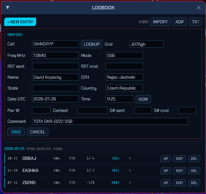
The logbook lists QSOs grouped by day (newest first) and covers both digital and manual entries. You can:
- + NEW ENTRY — add a manual QSO, seeded with the frequency you are actually working rather than the dial: in CW that is the dial plus your sidetone pitch, in RTTY and the other keyboard modes the dial plus the tone offset, and in phone the dial itself. Besides the basics (Call, Grid, Freq MHz, Mode, RST sent/received, Date/Time UTC with a NOW button, comment) the form carries Name, QTH, State, Country, transmit Pwr, and Contest fields (contest id and sent/received serial numbers). If you’ve already worked that call on the band, a ⚠ WORKED BEFORE badge appears. Press LOOKUP to fill name/QTH/grid from your callsign-lookup provider (see §10.2).
- EDIT / DEL — edit or delete an entry. Editing preserves fields the form doesn’t show (resolved DXCC/zones, QSL status).
-
IMPORT — load QSOs from an ADIF (
.adi) file. Imported records are de-duplicated against the log (same call + band within two minutes are skipped). Field lengths are read as the byte counts ADIF specifies, but exporters that count characters instead (QRZ’s logbook among them) are handled too, so accented names and QTHs survive the import intact. Records markedSWLare received reports, not contacts — the DECODES panel’s ADIF export writes them — and are left out; the network log line at the end of the import says how many.A file need not be Unicode. Plenty of Windows loggers write their national code page instead, and a Cyrillic or accented name in one used to stop the whole file — every callsign in it — from importing. Such a file is now read anyway: a byte-order mark or valid UTF-8 is taken at its word, and anything else is read as Windows-1251 or Windows-1252 depending on which the text looks like. That last step is a guess, and the network log line at the end of the import names the code page it went with, so a name that comes out as nonsense tells you which one to say when you report it. Everything the log is really keyed on — callsign, date, band, mode, frequency — is plain ASCII in all of them and imports correctly either way. Exports are always UTF-8.
- ADIF — export the whole log to
sdroxide-log.adi(also the file you sign with TQSL for LoTW). - TXT — export the whole log to
sdroxide-log.txt.
A small status column on each row shows QSL state: a green ✓ once a QSO is confirmed (LoTW, eQSL or card), a dim ↑ once it has been uploaded but not yet confirmed. Hover it for the per-service detail.
Records also hold the fields used by lookup, upload and awards — DXCC entity, CQ/ITU zones, IOTA and POTA/SOTA references, and per-service QSL status. See §9. Spotting, awards, and QSL upload for the one-click upload buttons and award tracking.
The log is stored in qso_log.json.
3.2.9 11 m and the citizens’ band (WSJT-CB)
On 11 m the whole exchange follows the conventions of the community’s WSJT-CB client rather than the amateur FT8 ones — because that is who is on the band to work. Press 11M in the band row and the mode’s band buttons land on the citizens’ band’s own channels as usual (6.1 lists them), but everything the sequencer puts on the air changes:
- No Maidenhead grid. CB stations do not carry locators, so the identity,
the report and the sign-off all leave the grid word out — in a slot that
would carry
JN78vethe band carries nothing instead (issue #396). Your own grid is still used for the map and the great-circle paths, just not transmitted. - The calls are WSJT-CB’s. A lone call —
26AT715— is free text on the wire, and that is how a CB station answers a CQ: no report, no pair, just the call. An addressed identity is hashed the way WSJT-CB hashes it and sent as a Type 4 message,<DX> MYCALL— the far station’s call as the hash first, your own call spelled out in the clear — which is the exact form the WSJT-CB client itself transmits, not a pair of hashes. The CQ itself goes out in the usual CQ form, grid-less. - The sequence is WSJT-CB’s. A CQ answered by a bare call gets a report;
the report, the R-report and the sign-off all travel one call at a time as
free text —
26AT715 -07,26AT715 R+05,26AT715 RR73,26AT715 73— each exactly as WSJT-CB writes it, so a contact with their client completes cleanly in the other direction too. - Every 11 m decode shows its country flag. A CB-shaped callsign is read by
shape, and its leading digits resolve as the CB country number —
26AT715is 026, England — using WSJT-CB’s own country numbering, so the flag, the entity and the sort-by-country the amateur decodes have are exactly what a CB operator is used to seeing (the reference’s own historical names — “East Germany”, “Czechoslovakia”, “Alaska” — come with it). - Logging and permission. A completed contact logs with an empty ADIF band — ADIF’s enumeration runs 12 m, 10 m, 8 m with nothing in between — and because the citizens’ band is a separate service rather than an amateur allocation the generic amateur-band lockout refuses to key up there until the station opts in: Allow transmit on 11 m (CB) on the General tab, confirmed once. CB is a two-way band — it is meant to transmit — so this is a one-time opt-in and not a restriction; it opens 11 m and nothing else, and the broadcast bands stay receive-only. Sending the digital modes needs a transceiver, keyed by VOX or CAT. Both are the band’s bullet in 6.1.
Modifier suffixes are plain WSJT-CB, and they just work. A station may put
the usual portable-style suffix on its 11 m call — 19DC373/P, /MM, /QRP,
or an event marker like /F1 — and this build accepts it, because WSJT-CB does.
It widens the standard callsign rules rather than replacing them, so those
suffixes ride on a CB identifier unchanged. Nothing has to be switched on, and
the country and flag on the decode row still resolve from the base call.
⚠ An 11 m callsign may not exceed 11 characters — including any
/zzzThis is a hard limit of the FT8 callsign field, not a setting and not a limitation of this build: a CB call travels in clear as a 58-bit base-38 number, and
38^11is just under2^58, so eleven characters is the ceiling for the whole identifier. Any implementation refuses a longer one.The suffix is counted.
19DC3733/Pis 10 characters and fits.19TST1001/QRPis 13 and cannot be sent by anyone — a station announcing it is announcing something that will not go out.Plan the activation call to this budget before you announce it. The slash counts too:
/Pcosts 2 of the 11,/F1costs 3,/QRPcosts 4, and the grammar allows up to 5 (/XXXX). However the call is written, base plus suffix must come to 11 characters or fewer:
Activation callsign Length Sendable 19DC3738 yes 19DC373/P10 yes 19DC3733/P10 yes 19DC373/QRP11 yes — exactly at the limit 19TST1001/QRP13 no 19DCG3733/P11 yes (needs the wide grammar, below) The same rule is checked live in Settings → General: type a too-long 11 m call there and it is flagged as it is typed, before the first transmission rather than after it.
This applies to the citizens’ band only. An amateur callsign is not held to this and is not flagged.
The experimental wider CB callsign grammar. WSJT-CB’s identifier shape is
N{1,3}L{1,2}N{1,3} — a country prefix, one or two letters, a unit number — and
that is what runs by default. The 11 m community has grown past it, and some
stations now use three-letter groups or four-digit unit numbers
(26ABC715, 26ABC1000), which that grammar refuses. Settings → General →
11 m / WSJT-CB callsign grammar → WIDE CB CALLSIGNS — EXPERIMENTAL accepts the
wider shape N{1,3}L{1,3}N{1,4} — and the matching slash form
N{1,3}L{1,3}/L{2} — on top of the default one, so everything the strict
grammar takes is still taken. It is experimental and off by default: WSJT-CB
itself does not accept the wider shape, so switching it on widens what this
station hears and lets it pack a wider call pair, but a call that needs it may
not be understood by a station running WSJT-CB. The toggle is not what makes
modifiers work — those are accepted either way, since they are WSJT-CB’s own
behaviour. Nor does it buy any extra length: it changes the shape a call
may have, and the 11-character ceiling above applies exactly as it does with the
toggle off, so 19DCG3733/P (11) is sendable and 19TST1001/QRP (13) is not.
A note on what a CB call looks like on the wire, because it is not a hash and the older wording here said it was. A non-standard call is carried in clear, as a 58-bit base-38 number, which is why it is at most 11 characters and why two different calls can never be confused for one another. The 22-bit hash belongs to only one case — the grid-less layout used when both stations are CB, where one call is abbreviated — and it is a property of the FT8 family, not of this setting.
3.3 PSK31 and RTTY
Choose PSK or RTTY from the DIGITAL menu of the Band/Mode popup. As with FT8/FT4/FT2 the panadapter switches to a zoomed sub-band waterfall, but the lower panel is a live messaging area instead of a QSO sequencer.
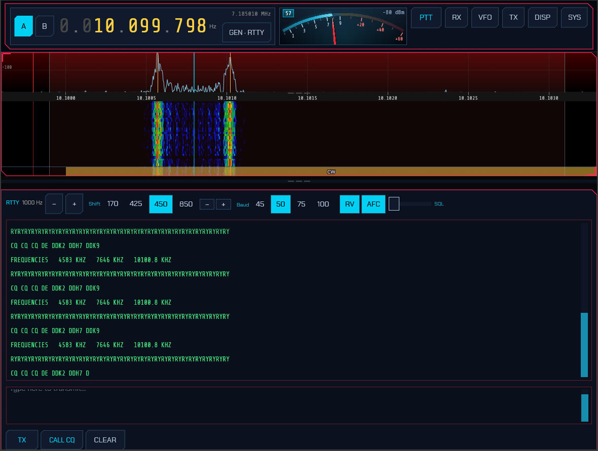
Receiving:
- Decoded text streams into the receive window as signals are copied.
- Tune exactly onto a signal with the −/+ buttons (±10 Hz) — or click its skimmer label (see Skimmers). In RTTY, two amber lines on the waterfall mark the expected mark/space tones to tune between.
- In PSK the cursor moves to the signal; in RTTY the signal moves to the cursor. Click the waterfall in PSK (or Olivia, THOR, FSQ, Hell) and the tone offset follows your pointer, which is how you work several stations inside one passband. RTTY does not work that way: its tones are standardised at 2125 and 2295 Hz, that is where everyone else’s receiver expects them and where a transmit filter passes them cleanly, so a click tunes the dial until the signal lands on the pair instead of dragging the pair onto the signal — just as CW does (2.14). The −/+ buttons still move the tones if you want them somewhere else.
- The MHz figure beside the offset is the frequency you are working, and the one to log and to give on the air. The big readout at the top of the window is the dial, which in RTTY sits a whole tone pair — about 2.2 kHz — below the signal.
- The SQL slider in the panel header is a decode squelch: raise it until the window stops filling with garbage when no signal is present, lower it (to the left) to copy weaker signals. It applies to every keyboard mode (PSK/RTTY/Olivia/THOR/FSQ).
- CLEAR RX in the panel header empties the receive window. Nothing that is on the air stops and the decoder keeps copying — it only tears off the page, which is what you want before answering a CQ on a frequency you have been monitoring for an hour. Every mode that copies text has this button, and it is never the same one as the CLEAR below the transmit box (that one stops what you are sending).
Transmitting (type-ahead):
- Type your reply in the transmit box and press TX to key up. Text is sent as you type; characters that have already gone out turn green, so you can watch the transmission catch up when you pause.
- CALL CQ loads a CQ macro and starts sending it; CLEAR empties the buffer and stops; pressing TX again unkeys.
- MSG opens the message editor: up to ten buttons of your own text — working conditions, the weather, a standard reply — each sending its whole line in one press, with F1–F9 for the first nine. It is the same control the CW panel carries, on a list of its own, and it is saved with the station’s configuration (2.14).
- SEND ON RETURN changes that to a line at a time: nothing leaves the box until you press Return, and then the whole line goes out and the over starts on its own. Type at your own pace, read it back, correct it, and commit it when it says what you meant — nothing half-typed is ever on the air. Shift+Return breaks a line without sending it, and TX commits the box the same way Return does. The over ends with the line: transmit releases once the text has gone out, instead of holding the carrier up with idle reversals while you compose the next one. Pressing TX over an empty box still holds the channel, if that is what you want. The setting is shared with Olivia, THOR, Hellschreiber and CW (2.14), where it earns its keep for a second reason.
Settings (PSK/RTTY setup dialog):
- PSK is BPSK31 — differential BPSK with the standard varicode alphabet.
- RTTY defaults to 45.45 baud, 170 Hz shift, Baudot (ITA2), on the standard 2125/2295 Hz tone pair. Shift (170 / 425 / 850 Hz) and Baud (45 / 50 / 75) are selectable; a wider shift keeps the same centre and spreads about it.
- Your callsign and grid (shared with the FT8/FT4/FT2 setup) fill the CQ macro.
Skimmers: the PSK and RTTY skimmers (see Skimmers) label signals across each band’s PSK/RTTY calling sub-bands. Clicking a label from any mode switches to PSK or RTTY, tunes onto the signal, and opens this panel — onto the standard tone pair in RTTY, so the offset you land on is the one you will transmit. A label already in that mode leaves your own offset alone.
On VHF and UHF, use RTTY-FM instead. Some national societies still send their weekly bulletin as RTTY on a 2 m FM channel, and that is not the same signal as RTTY on a sideband — the tone pair modulates an FM carrier rather than riding on one edge of a passband. RTTY-FM is on the DIGITAL menu beside RTTY.
Everything about the modem is the same: the same Baudot alphabet, the same 2125/2295 Hz tone pair, the same shift, baud and Reverse controls and the same panel. What differs is the radio and the frequency:
- A CAT-controlled rig is put in FM data (PKTFM / FM-D) rather than in USB.
- The dial is the channel, not the foot of a passband, so nothing is offset from it — a contact is logged on the frequency you tuned, where an HF RTTY contact is logged 2.2 kHz above it.
- The passband is an FM channel’s, ±8 kHz, selectable 8k / 16k.
- The transmit level is deviation and comes from the FM half of the digital transmit level (2.10), which is the same rail VHF packet and APRS use.
Its band buttons are the FM calling channels — 50.150, 145.500 and 433.500 — because RTTY on FM has no worldwide convention at all: where it is still used the frequency comes from the society running the bulletin. Tune the real one and store it in a memory.
3.3a SYNOP and SHIP — coded weather reports (BETA)
BETA. The decoder is tested against four real published messages and decodes all of them, but no report has been read off the air by this code yet. If you try it and the numbers look wrong, or a report does not appear at all, please say so — that is what this note is for.
Ships and land stations broadcast the weather where they are as coded numbers on HF RTTY, every few hours. It is the plainest service on the shortwave band: no internet, no account, no timeslot booking — just a schedule you can read off a piece of paper.
Set RTTY, 50 baud, 170 Hz shift, and listen on one of:
| kHz | Who |
|---|---|
| 4583 | German weather service (DKD/DWD), 24 h |
| 7646 | the same, worldwide schedule |
| 10100.8 | the same, higher power |
They go out roughly every six hours across two codes:
| UTC | Code | What |
|---|---|---|
| 02:00, 07:35 | SHIP — WMO FM 13 | ships |
| 00:35, 12:10 | SYNOP — WMO FM 12 | land stations |
| 08:15, 20:15 | BUOY — FM 13 | buoys |
These are the quietest hours on the band. Leave it running.
The line arrives as a wall of figures and means nothing on its own:
BBXX BRAVO 20123 99252 10595 41494 81412 10285 20269 40100 53012 79586 8597/ …
When one is recognised, a WEATHER chip appears beside the message box with the number of reports heard. Press it and a window lists them newest first, each one giving:
- the station and the time it was observed — from
DDDandYYGGiw; - the position, in degrees — the quadrant digit fixes both hemispheres;
- wind, with the unit the report asked for rather than an assumed one;
- pressure, air and dew-point temperature, sea temperature;
- cloud amount and type, visibility, and present and past weather, spelled out rather than left as two digits;
- for a ship, course, speed, waves and swell — and the speed is a range, because the code is a range;
- the raw line, kept above the decoding, because a listener checking a report against the original needs the figures and not just the interpretation.
A slash is an answer, not a gap. Groups like 8597/ mean not reported —
neither zero nor missing — and are shown as not reported. A blank there would
read as our fault rather than the station’s.
Anything the decoder does not recognise as a group is kept and shown as the station’s own words. Human-entered reports put the interesting part in exactly that way, and it is the part worth reading.
Nothing leaves the program: the list is for this session only, because a report read tomorrow is a lie about when it was observed.
3.4 Olivia, THOR and FSQ
Three more keyboard modes are on the DIGITAL menu. Olivia and THOR reuse the same messaging panel as PSK/RTTY — including SEND ON RETURN (3.3), which is worth a look in these modes in particular: at 32/1000 Olivia a typed correction takes long enough to send that it is better not to have sent the mistake. Each mode’s submode is chosen on its setup page (⚙ SETUP):
- Olivia — a slow, extremely robust MFSK mode with Walsh/Hadamard block coding. Choose the tone count (2, 4, 8, 16, 32, 64) and bandwidth (125–2000 Hz). The symbol rate is bandwidth ÷ tones; 32/1000 and 16/500 are the common combinations. Both stations must use the same tones/bandwidth. Both directions work: other stations’ Olivia decodes (confirmed against a real recording), and our own transmission is decoded by our own receiver at every tone count. What has not been proven is another program copying us — no fldigi or MultiPSK has been on the receiving end of an over from this build — and we send no sync tones yet, which is how fldigi finds a frame. So send one short over and ask for a report rather than expecting an answer.
- THOR — a DominoEX-family 18-tone mode using incremental frequency keying (IFK+) with convolutional forward error correction. Choose a submode (THOR4 … THOR32); THOR16 is the usual default. The tone bank edges are drawn on the waterfall.
FSQ (Fast Simple QSO) has its own panel for the directed FSQCALL layer. It is a 33-tone incremental-FSK mode; choose the speed (FSQ-2/3/4.5/6) and an FSQ call on the setup page (defaults to your callsign):
- Heard list (left) — every station whose transmission is decoded is listed, most-recent first. Click a callsign to make it the directed target.
- Compose (right) — the To: line shows the current target (or ALLCALL).
Type a message and press SEND (or Enter); sdroxide prefixes your call and
transmits one burst (
YOURCALL:TARGET message). ? heard asks the selected station to send its heard list; incoming?queries addressed to you are answered automatically. CALL CQ sends a broadcast CQ. - Contacts — the CONTACTS button opens an address book (persisted in
contacts.json). Add callsigns, give them names, click TO to target one, or DEL to remove. - CLEAR RX in the panel header empties the decoded stream and the directed
messages drawn over it. The heard list stays — it is a separate pane, and it is
what an incoming
?query is answered from. - Images — Send image… picks a picture, which is scaled to grayscale and transmitted as an analog tone scan; received pictures appear in the image gallery below. Nothing here is written to disk, so clearing it is local and immediate: right-click a picture to remove it, or CLEAR to forget the lot.
These three modems are native-Rust and self-contained. On-air interoperability with fldigi is being validated; the first release targets clean-to-moderate signals.
3.5 Hellschreiber
Choose HELL from the DIGITAL menu for Hellschreiber — the oldest digital mode still in regular amateur use, and the only one you read with your eyes instead of a decoder.
Hell does not send characters. It sends pictures of characters: the transmitter scans a 7-column by 14-row dot matrix per letter, top to bottom then left to right, switching the carrier on and off as it goes. The receiver simply free-runs at the same dot rate and paints whatever it hears onto a scrolling strip. There is no synchronisation, no framing and no error correction — which is exactly why Hell stays readable in conditions that break real decoders. A burst of noise smudges a few dots instead of corrupting a whole character, and your eye does the rest.
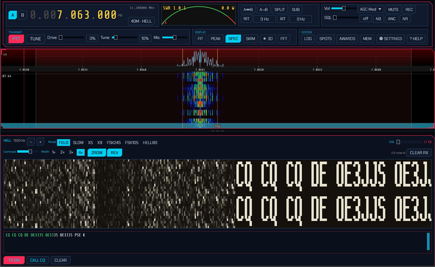
Reading the strip. Received text scrolls in from the right. Because nothing synchronises the vertical position, a character can straddle the top and bottom of the strip — so, like fldigi, sdroxide draws every column twice, stacked. Whatever the alignment happens to be, one complete legible copy of the text is always on screen. That is what the 2ROW button controls; turn it off for a single-height strip and drag the raster up or down to line the text up yourself.
Panel controls. The header carries the audio-tone readout with −/+ nudges, the variant buttons, and the decode squelch. Below that:
- Contrast — hardens or softens the dots. It redraws the entire scrollback, not just what arrives next, so you can rescue text that has already gone by.
- Width —
1×to4×screen pixels per received column. Square dots would fit only about eighteen characters across the panel; the default2×shows around sixty. - 2ROW — the doubled display described above (on by default).
- REV — reverse video: light dots on dark paper instead of the classic look.
- CLEAR RX — wipe the strip.
Transmitting works like the other keyboard modes: type in the box and press TX. Characters already sent turn green. CALL CQ loads a CQ using your callsign, and CLEAR empties the buffer and stops. While TX is held with nothing to send, Hell transmits blank paper rather than dropping the carrier, which is how it holds a channel between overs — so press TX again to release. Your own transmission is painted onto the same strip as it goes out, which is the only confirmation Hell offers that your timing and font are right.
SEND ON RETURN (3.3) applies here too, and Hell is the mode where the difference is plainest: a correction typed live is already on the paper — the receiving operator watched you make it — while one made before you press Return never existed. The strip then ends with the line: transmit releases once the text has been painted, rather than holding the channel with blank paper for as long as you take to type the next one. Pressing TX over an empty box still holds it, so the between-overs habit is there when you want it — it is simply no longer what composing a line does. The break itself has no glyph, so it goes out as one blank cell, which is the gap you would have typed between lines anyway.
Variants. Seven, matching fldigi’s set:
| Variant | Speed | Bandwidth | Keying |
|---|---|---|---|
| FELD | 2.5 char/s | 295 Hz | on/off keyed |
| SLOW | 0.3 char/s | 35 Hz | on/off keyed |
| X5 | 12.5 char/s | 1470 Hz | on/off keyed |
| X9 | 22.5 char/s | 2645 Hz | on/off keyed |
| FSK245 | 2.5 char/s | 490 Hz | frequency-shifted |
| FSK105 | 2.5 char/s | 220 Hz | frequency-shifted |
| HELL80 | 5 char/s | 1200 Hz | frequency-shifted |
FELD (classic Feld Hell) is what essentially all on-air activity uses; the others are worth knowing about but you will rarely meet them. SLOW trades speed for a 35 Hz bandwidth that survives conditions nothing else will. X5 and X9 are fast but wide — X9 occupies nearly the whole SSB passband, so the tune control clamps it near the middle where it fits. The FSK variants keep the carrier up and shift it instead of keying it, which suits a linear amplifier better and gives a noticeably cleaner raster.
Hell transmits on USB. The band buttons are preset from the hellschreiber.com narrow-band digimode band plan (18 March 2019), using its common calling and operating frequencies:
| Band | Preset | Band | Preset |
|---|---|---|---|
| 160 m | 1.840 | 17 m | 18.104 |
| 80 m | 3.574 | 15 m | 21.063 |
| 60 m | 5.3515 | 12 m | 24.924 |
| 40 m | 7.040 | 10 m | 28.063 |
| 30 m | 10.144 | 6 m | 50.286 |
| 20 m | 14.073 |
These are IARU Region 1 values where that band plan splits by region, and — unlike the band plans and the other modes’ calling frequencies — they do not follow the IARU region setting: Hell has no per-region table published to follow. Region 2 and 3 differ on 160 m and 80 m in particular. Bands quoted as a range use its low edge, so tune up from the preset to find activity. 6 m is not in that band plan and comes from the Feld Hell Club.
On 15 m and 10 m the presets are 21.063 and 28.063 rather than the 21.074 / 28.074 the band plan names as calling frequencies, because those two sit squarely in the FT8 sub-band — and fall outside the operating ranges the same table lists beside them.
Hell is a “fuzzy mode” (J2B), so it may be sent in either the CW or the phone segments; band plans are recommendations, and listening before you key matters more here than the numbers do. Check them against a current plan for your region.
3.6 SSTV
Choose SSTV from the DIGITAL menu to send and receive pictures. The panel has a received-image gallery on the left and a transmit compositor on the right, with a row of mode buttons across the top: Auto, Scottie 1, Scottie 2, Scottie DX, Martin 1, Martin 2, Robot 72, Robot 36, SC2-180, SC2-120, and the PD family — PD50, PD90, PD120, PD160, PD180, PD240 and PD290.
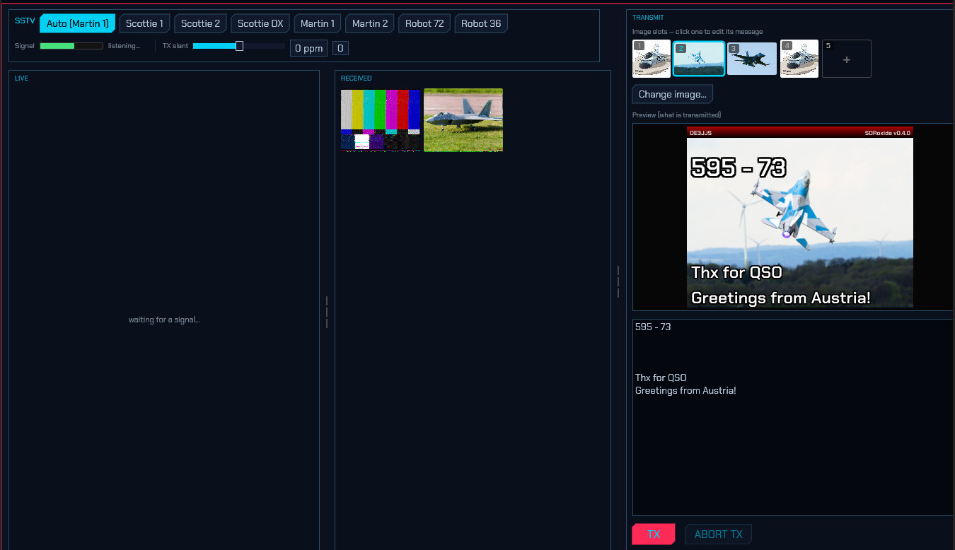
Auto (the default) auto-detects the mode on receive — from the VIS header, or, if you tune in mid-picture, from the sync cadence — and transmits in Martin 1 until a mode has been detected. Selecting a specific mode instead pins both the receive decoder and the transmit compositor to that mode.
The PD family is worth knowing about if you have only ever used Scottie and Martin: it sends the colour information for two lines at once, which buys a bigger picture for the same air time. PD120 and PD180 are 640×496 and PD290 is 800×616, against 320×256 for everything else — and PD120 is one of the two or three modes you are most likely to meet on 3.730 and 14.230. Wraase SC2-180 is the other, at 320×256 in three minutes. The transmit compositor follows the mode’s size automatically, so picking PD180 gives you a 640×496 canvas to crop into.
If a mode arrives that sdroxide does not have, the panel says so where it
would otherwise say listening… — for example Pasokon P3 — not decoded. That
is not a fault at your end: the header was read perfectly and there is simply no
decoder for that one. Before 1.6.9 nothing was said at all, which made an
unimplemented mode look exactly like a broken receiver (issue #421).
Band buttons tune to that band’s common SSTV calling frequency, staying in SSTV. 14.230 MHz on 20 m, 21.340 on 15 m and 28.680 on 10 m are the same the world over; 80 m and 40 m split by region and follow the IARU region setting (6.1) — 3.730 and 7.165 in Region 1, 3.845 and 7.171 in Regions 2 and 3. Above HF, 144.500 on 2 m and 432.500 on 70 cm, the narrow-band SSTV activity centre.
Choosing the SSTV mode does the same thing. Selecting SSTV while already on a band moves the dial to that band’s SSTV frequency, so “pick the band, pick the mode” lands you on the pictures rather than wherever the last mode left you. On 11 m that is 27.700 MHz, the community’s picture frequency, with 27.255 (channel 23) and 27.375 (channel 37) as the in-band alternatives. This is the same rule the slotted digital modes and WSPR have always used, extended to SSTV and SSTV-FM; it only ever rescues a dial that is nowhere useful, because a dial already sitting on one of the mode’s own frequencies is never moved — nor one within 3 kHz of it, or one you saved yourself with ⇵ FREQ below.
To decode SSTV anywhere, light KEEP DIAL beside the ⇵ FREQ chip. With it on, choosing SSTV leaves the dial exactly where you tuned — a local net, a picture heard somewhere off the list — and the published frequencies stay one click away in the picker. It is remembered, and it covers SSTV and SSTV-FM only: FT8 and the other slotted modes still move, because off their frequency they decode nothing. Without it, the same is reached by choosing SSTV first and tuning afterwards — a dial moved once the mode is chosen is never moved back.
The ⇵ FREQ chip at the top left of the panel is where that frequency list
lives: it shows the calling frequency and the alternates, tuning the dial when
you pick one, and letting you save a frequency of your own — which is how you
keep one a local group has settled on. The chip doubles as a readout, showing
⇵ 27.700 when the dial is on one of the listed frequencies and plain ⇵ FREQ
when it is not.
Which sideband: SSTV is a phone emission and follows phone practice rather than the other digital modes’ fixed USB — LSB on 160, 80 and 40 m, USB on 20 m and up. sdroxide switches for you: the passband flips to the other side of the dial as you tune across the boundary, and a CAT-controlled rig is commanded into the matching sideband. Nothing to set, and nothing to undo when you go back up — a picture sent on the wrong sideband arrives at everyone else inverted.
Plain sideband or the rig’s data mode: the picture is modulated here and
reaches the radio through its sound card, exactly as FT8 does, so SSTV obeys the
Digimode mode setting (6.2)
like every other digital mode. Leave it on DIGI and a rig with a DATA
position is put in USB-D above 40 m and LSB-D at and below it, which is what
takes the transmit audio from the USB/data input rather than the microphone. On
USB the rig is put in the plain sideband instead — the right answer for a
radio whose SSB modulation source is already set to USB, or one with no data
mode at all.
On VHF and UHF, use SSTV-FM instead. Above 30 MHz a picture is normally sent on an FM carrier rather than a sideband, so the DIGITAL menu has a second entry — SSTV-FM — beside SSTV. Everything about the picture is the same: the same transmission modes, the same decoder, the same gallery and the same compositor. What differs is the radio underneath. SSTV puts a CAT-controlled rig in USB (or LSB); SSTV-FM puts it in FM, and the dial is the centre of a channel rather than the foot of a passband.
Its band buttons are the FM image channels: 50.510 on 6 m, 144.500 on 2 m and 433.400 on 70 cm — the IARU Region 1 plan’s own, the last of which it names as SSTV (FM/AFSK). Region 2’s plan appoints no image channel at all (the ARRL 2 m plan calls 145.50–145.80 “miscellaneous and experimental modes”), so a Region 2 station is offered 145.500 marked as common practice rather than as something a plan says. Region 3 names none, and none is offered.
Pick by what the other station is doing, not by the band alone: 2 m SSTV on sideband is a thing people do, and both modes are available everywhere. If a picture is audible but decodes as noise, the usual cause is being in the wrong one of the two.
Receiving:
- Incoming pictures decode scanline-by-scanline and appear in the LIVE view as they arrive, then land in the RECEIVED gallery (newest first).
- The Signal meter shows the receive audio level so you can confirm audio is reaching the decoder and set your input gain.
- In Auto, the mode is identified from the VIS header (or the sync cadence if you tuned in mid-picture) and pre-selected for your next transmission — no need to pick it.
- Restart RX abandons the picture being received and starts listening for the next header. Once the decoder has locked on it is committed for the whole length of that mode, and the slow ones are long — Scottie DX runs four and a half minutes — so a header misread as a slow mode takes the receiver off the air until it runs out. On QO-100, where one station follows another over the same transponder, that is the next few pictures gone. Press this and the half-picture is dropped and the receiver is hunting again. It is a receive control only: it does not touch a transmission in progress (that is ABORT TX) and it does not put the mode selection back to Auto.
- Received images are saved as PNG under
~/.config/sdroxide-brown/sstv_rx/and reload into the gallery next time. - Sending one back out — Re-upload. Open a received picture and Re-upload loads it into the transmit slot you have selected, so you can send it again for the stations who could not copy it and have them relay it onward. It loads the slot and stops there: sending is still a deliberate press of TX, exactly as it is for anything else, so a click inside a picture window can never key the transmitter by accident. On a receive-only radio the chip is greyed and says why — composing a picture is worth doing on a receiver, sending it is not.
- Saving a copy — Save image as…. Writes the picture where you choose. It asks; the name says so, because “save picture” read as it has saved one and a picture’s worth of clicks going somewhere unexpected is how that happens.
- Sending someone the picture — Share picture…. SSTV has no QSL audience: the stations on it are amateurs and 11 m operators, reached through QRZ and the online DX communities, so this is a friend being sent a funny picture — which in France, where SSTV is a busy mode, is most of the fun of it. In a browser it hands the picture to the phone’s own share sheet, so WhatsApp, Telegram, Signal, Mail and everything else you already have are in one list, with the picture in the message rather than as a file you then have to go and find. One tap. Everywhere else it saves the picture and opens a message to send it from, with To, Subject and a Message pre-filled — a short reception note (where and when it was heard, and the reports you type) and room for your own sentence, so the usual case is edit and send rather than compose from nothing. Attaching the picture is one click in your mail program, and the program cannot do it for you. That is not an omission to be worked around: sending mail means being a mail client, with an account, a password and a server, which is a different program with its own security to consider. What this does is everything up to that point.
- Deleting. Most of what a night on 20 m leaves behind is noise. Right-click a thumbnail and choose Delete this picture, or open one and use Delete… in the enlarged window — which asks a second time, because the file goes for good and there is no undo. The picture is removed from the store on the machine the radio is plugged into, so it is gone from every screen attached to it, and a browser client can clear the collection down without going near that machine. Deleting the picture you are looking at leaves the window on the next-older one, so a run of blank frames can be thrown away in a sequence of clicks.
Transmitting:
- The TRANSMIT side has five image slots that work like tabs. Click a
slot to make it the active tab (highlighted with a cyan border and its number);
the message box below then edits that slot’s message. Use the Load image…
button (or double-click a slot) to pick an image file, which is
automatically cropped and scaled to the current mode’s dimensions and stored
under
~/.config/sdroxide-brown/sstv_tx/. - Type a message for the active slot. Each slot keeps its own message —
switching slots swaps the text — and the messages are saved to
~/.config/sdroxide-brown/sstv_messages.json, so they persist across restarts. The lines are drawn over the image in bold with a black outline for readability; the first line is rendered at double size as a title. A live preview shows exactly what will be transmitted, banner and all. - Banner… opens the editor for the strip across the top of every picture
this station sends. Out of the box it is the one sdroxide has always drawn: a
red→black strip with your callsign at the top left and
SDRoxide+ the version at the top right. All of it is yours to change:- Top left and Top right are free text, with three placeholders
substituted when the picture is composed —
{call}(your callsign, put into capitals),{grid}(your locator) and{version}(the sdroxide version). Anything else in braces is printed as you typed it, so a mistyped placeholder shows up in the preview instead of quietly printing nothing. Leave a field empty to print nothing at that end. - Colours — the strip at its top edge (it fades to black at the bottom), and the colour both texts are printed in.
- Height — how tall the strip is, in pixels of the transmitted picture (8–64, default 16). The text is sized from it, so this is the control that matters: an SSTV frame is only 320 pixels across and lands on the other operator’s screen as a small window, and a 16-pixel banner is hard to read there.
- Untick Draw the banner to send the picture and its message with nothing over the top, and Reset puts the whole thing back to the callsign and the version.
The banner belongs to the station, not to the slot and not to the screen: it is drawn into the picture that goes on the air, so it is saved with the rest of your digital-mode settings and every screen attached to the radio — the console and the browser tab — composes the same slot identically. (Your callsign itself is set on the General settings tab, or in the FT8 setup dialog.)
- Top left and Top right are free text, with three placeholders
substituted when the picture is composed —
- Press TX to transmit the composed image; ABORT TX stops a transmission in progress.
- TX slant trims the transmit clock (in ppm) to remove slant seen on a receiver whose sound-card clock differs slightly from yours — nudge it until a test picture decodes straight on the far end; 0 resets it. It applies to the next transmission and is persisted. (Received pictures are auto-deslanted by sdroxide, so this is only for the transmit direction.)
- FSK ID sends your callsign as tones for about two and a half seconds after each picture, in the format MMSSTV published and every SSTV program and unattended repeater reads. This is the identification a machine can act on: a repeater logs and announces the station that just sent, which no banner drawn into the picture can give it. It is on by default and sends nothing at all until you have set a callsign (§6.1). sdroxide reads them too — a callsign heard this way appears as ID beside the mode readout, and stays there until another station sends one. A receiver that tuned in halfway through a picture still gets it, because the ID does not depend on having caught the header.
- TX lead is how long sdroxide sends silence after keying the transmitter before the picture’s own leader and VIS code go out — 500 ms by default. That header is what tells the far end a picture is coming and which mode it is in, and a decoder that misses part of it does not draw a late picture, it draws nothing at all. On a CAT-controlled rig the moment PTT is asked for and the moment RF is really on the air are not the same one — sdroxide alone spends 165–240 ms getting there, and the rig’s T/R relay, PLL and PA settling come on top — so the header goes out into the gap unless something covers it. Turn it up if a WebSDR or OpenWebRX on the far end hears your transmission but shows no image; turn it down to 0 on an SDR that keys in milliseconds.
Note: SSTV decode/encode runs in the server engine, so the panel works the same in the native app and the browser client. RX quality depends on signal conditions — clean signals decode well; weak or drifting signals may slant or show noise (ongoing refinement).
3.7 RIFP (Radio Image Framing Protocol)
Choose RIFP from the DIGITAL menu to send and receive pictures over
draft-dulaunoy-rifp-00 —
a packetised image protocol, and the only mode here that is not single
sideband. Its rifp-cpfsk-4800 radio profile keys the carrier itself:
continuous-phase binary FSK, 4800 baud, ±4 kHz deviation, in a channel about
25 kHz wide. The dial is the middle of the signal, not its lower edge.
The panel is the SSTV panel — the same live picture, the same received gallery, the same five transmit slots with their own overlay messages — with a RIFP control strip in place of the SSTV mode buttons. Pictures you load are shared between the two modes.
⚠ Bandwidth. 25 kHz does not fit in a narrow-band segment. sdroxide will transmit RIFP wherever you tune it, and the panel says so in red whenever the dial is somewhere the channel does not fit. The segments it treats as wide enough are 10 m FM (29.510–29.700), the 6 m all-modes part (50.5–52.0), the 2 m all-modes part (144.500–144.794) — where the image and facsimile modes have always lived — and 70 cm (430–440). The band buttons in the Band/Mode popup land in each of those while staying in RIFP, and the 433.920 button jumps to the calling frequency the draft names. Allocations differ by country and your own licence may be narrower than 25 kHz even inside those — checking that is yours to do, not the software’s.
The controls:
- CPFSK 4800 — the radio profile. One is defined so far.
- Size — the transmitted picture size (RIFP fixes none of its own). Everything is time: 320×240 at 4 bits takes a couple of minutes.
- Encode — how the picture becomes the object RIFP carries: G4 (CCITT Group 4 facsimile, bilevel, usually the smallest for line art), PNG, Zlib or RLE8 (compressed packed raster), Raw (the packed raster itself), JPEG (lossy), or Auto, which tries each and sends the smallest — never the lossy one unless you ask for it.
- Gray — grayscale depth, 1/2/4/8 bits. RIFP’s raster is grayscale by definition: its manifest has no way to describe colour. Dither diffuses the quantisation error, which is worth having below 8 bits.
- Repeat data — how many times each data frame is sent. RIFP is unidirectional with no repair requests, so repetition is the only recovery a receiver gets; two is the default. Chunk sets the payload octets per frame (192 is what the profile recommends).
Receiving:
- The Signal meter is a modem lock indicator, not an audio level: it rises when the receiver is actually reading FSK symbols rather than noise.
- Each transfer appears in the control strip as the sender’s ID (or the start of the session ID), the chunks received against the total, and a chunk map — one lit cell per chunk that has arrived, so you can see where the holes are. ✕ forgets an incomplete transfer.
- With the Raw encoding the picture paints row by row as chunks land. The other encodings cannot be decoded until they are whole, so they appear all at once.
- A picture is only shown after the reassembled object matches the manifest’s size, CRC-32 and SHA-256. Nothing partial or unverified reaches the gallery. Enlarge a received picture to see who sent it, how it was carried, and how many chunks arrived first time.
- The counters read frames (valid), bad (failed their CRC and were not recovered) and pictures (complete and verified).
- Received pictures are saved as PNG under
~/.config/sdroxide-brown/sstv_rx/, alongside the SSTV ones — and are deleted the same way (3.6): right-click a thumbnail, or Delete… in the enlarged window.
Transmitting: identical to SSTV — pick a slot, load an image, type its message, press TX. The status line shows which frame of how many is going out and how long is left. Your callsign travels as the protocol’s Sender ID extension.
3.8 Weather fax (WEFAX / radiofax)
Choose WEFAX from the DIGITAL menu to receive the weather charts the meteorological services broadcast on short wave — surface analyses, wave heights, ice edges, satellite composites. It is receive only: these are commercial and military transmitters, and an amateur station has nothing to send back.
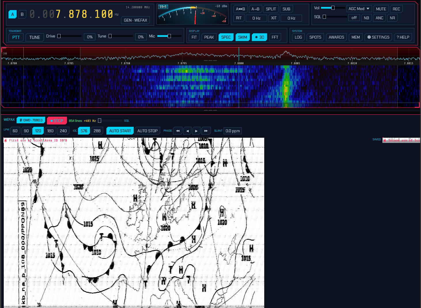
Finding a signal. The STATIONS button lists the schedules — DWD Pinneberg, Northwood, the US Coast Guard transmitters, Halifax, Tokyo, the two Australian ones — and picking a frequency tunes the dial. Note that the frequencies in every published schedule are the assigned carrier, and USB reception needs the dial 1.9 kHz below it: 7880 kHz is tuned at 7878.1. The picker does that subtraction for you, which is worth knowing because getting it wrong is the commonest reason a chart comes out as a blank page.
Like NAVTEX, WEFAX is a timetable. A station sends its charts at set times on set frequencies, so for most of the day a picked frequency is simply quiet — that is normal, not a fault. The schedule is when to be there. It also changes (a station closes, a frequency moves), so treat the listed times as a good guide rather than a guarantee: if nothing comes at the advertised time, try the next frequency in the list before deciding anything is broken.
Tuning. The +0 Hz readout beside the START button is the subcarrier’s
offset from where it should be. Tune for roughly zero, green: a fax subcarrier
runs 1500 Hz for black to 2300 Hz for white, and a receiver a few hundred hertz
off clips the picture to solid black or solid white. You will hear the signal as
a warbling two-tone note.
Starting and stopping. A transmission opens with a five-second start tone and closes with a stop tone, and with AUTO START and AUTO STOP on sdroxide uses both — leave the mode running and charts appear on their own. Since a chart takes a quarter of an hour, though, you will usually have tuned to one already in progress: press START to begin recording mid-chart, and STOP to end it and save. Turn AUTO STOP off to record straight through a station sending several charts back to back.
A stop tone is five seconds long and it is the first thing a fade takes, so AUTO START does not wait for one: while a chart is being drawn sdroxide also listens for the next transmission — its start tone, and failing that the thirty seconds of phasing signal behind it, which is far too long to miss. When one turns up the page in progress is saved and the new one is phased from the top, so a station sending chart after chart gives you one straight page each rather than one endless page with every chart after the first shifted sideways. Turning AUTO START off turns that off too: the capture then runs until you press STOP, which is what an operator recording a continuous transmission wants.
Geometry. Nothing in the signal states the line rate, so:
- LPM — lines per minute. 120 is what essentially every weather service uses; the others are there for the occasional 60 or 240 LPM transmission.
- IOC — index of cooperation, which fixes the line length: 576 gives 1809 pixels per line and is what charts use, 288 gives 904. The start tone announces this one (300 Hz for 576, 675 Hz for 288), so with AUTO START on it is chosen for you.
Straightening the picture. Two controls, and both are normal to need:
- PHASE ◀ ▶ shifts the picture sideways in 10- or 100-pixel steps. A chart begins with about thirty seconds of phasing signal that tells sdroxide where a line starts; if you tuned in after that went by, the chart arrives cut vertically and wrapped, and this is what puts it back together. The shift applies to the part of the chart already received as well as the lines still to come, so the whole picture moves at once and the saved image is corrected with it (issue #439).
- SLANT trims the sample clock in parts per million. If the chart leans to the left, increase it; to the right, decrease it. A sound card a hundred ppm off — well within tolerance — walks a fifteen-minute chart most of a line sideways, so this is the setting every fax operator ends up with a value for. Once you have found yours it is remembered.
On the globe. While you are tuned to a station in the list, the 3D solar view (7) draws the path from your QTH to that transmitter, exactly as it draws the station you are working in FT8. Weather fax carries no callsign and no grid square, so this is the only thing that turns an anonymous chart into “this came 900 km across the North Sea” — and it makes the propagation obvious when a station you can hear all night in winter vanishes at noon.
The picture. The chart paints line by line as it arrives, in a view you can scroll and zoom while it is still coming in — a chart takes a quarter of an hour, and there is no reason to wait for the bottom of it before reading the top. The VIEW controls decide how it is shown:
- FIT scales it to the panel width, WHOLE shrinks it until all of it is in view at once, and 50% / 1:1 / 2× are fixed magnifications. At 1:1 one screen pixel is one fax pixel, which is what you want for reading small print on a chart.
- HEIGHT stretches the picture vertically, ×0.25 to ×4. A chart that comes out squashed or stretched is being decoded at the wrong line rate — this makes it readable, and the LPM buttons fix it properly.
- FOLLOW keeps the newest lines in sight. Scrolling up turns it off so you can read what has already arrived without the view snapping back every half second; scrolling back to the bottom turns it on again.
The gallery. Completed charts are written as grayscale PNG to
~/Pictures/sdroxide/wefax/ — with your pictures rather than in a hidden config
directory, because a weather chart usually gets printed, mailed or opened next
to a routing program, and all of that happens in a file manager. Each is named
for when it was received and what it was tuned to:
wefax-20260729-141530Z-7878.1kHz-DWD.png
that is, UTC date and time, the dial frequency, and the station’s callsign when the dial is on a published schedule. The strip on the right of the panel lists them newest first, each labelled with its date, time and station; click one to open it full size, which you will need to — the fronts and isobars are unreadable at thumbnail scale — and ◀ NEWER / OLDER ▶ step through the rest without closing the window. PATH copies the directory.
A station that keys up over a dead band fills the directory with grey pages, so charts can be thrown away from the panel: right-click a card and choose Delete this chart, or use DELETE in the open chart’s window, which asks a second time before the file goes. The chart is deleted on the machine the radio is plugged into and disappears from every screen attached to it. Deleting the chart you are viewing leaves the window on the next-older one — the same place OLDER ▶ would have gone — so a run of blank pages goes in a sequence of clicks.
Charts saved by earlier versions in ~/.config/sdroxide-brown/wefax_rx/ are still
listed alongside the new ones, so nothing you have already received disappears.
Deleting one takes both copies, so a chart that was in the old directory too
does not reappear on the next listing.
3.9 JS8
Choose JS8 from the DIGITAL menu. JS8 uses FT8’s waveform — the same eight tones in the same 79-symbol frame — but carries a conversation instead of a contest exchange: free text, questions you can ask another station, and a periodic “I am here” heartbeat. Because it is slotted like FT8 it decodes far below the noise floor, and because it is a conversation it is slow. A sentence takes about a minute. That is the trade. Selecting it puts the dial on the band’s JS8 frequency — 14.078 on 20 m, and the traffic in the 3 kHz above it (3.1).
Speeds. Four of them, on buttons in the panel header:
| Speed | Slot | Width | Use |
|---|---|---|---|
| SLOW | 30 s | 25 Hz | The weak-signal end |
| NORMAL | 15 s | 50 Hz | The band convention; nearly all traffic |
| FAST | 10 s | 80 Hz | Good conditions, shorter waits |
| TURBO | 6 s | 160 Hz | Local and VHF work |
They are drawn in that order — slowest and narrowest first, fastest and widest last — because that is what they are: one dial, not four unrelated choices.
Both stations must be on the same speed to work each other — they are different waveforms on different slot clocks, not different settings of one receiver, so a station transmitting NORMAL is not something a TURBO receiver can hear. Normal is what you want unless you have agreed otherwise.
MULTI, the chip set apart to the right of the four speeds, decodes all of them at once (issue #358). All four speed buttons then light, because all four are being listened to, and a small ▸ marks the one you transmit at — click another to move it. Everything on the band is decoded whatever speed it is on, so a station calling you from another one appears in the heard list instead of not existing, and you can drop onto its speed to answer. In the conversation list each message then carries a one-letter tag after its time — S, N, F or T — saying which of the four it came in on; hover it for the name. Without it there is nothing on screen to tell a quiet band from three quarters of a busy one. It costs about four times the receive CPU — four separate decodes on four separate slot clocks — which is why it is off by default; a slot that arrives while the decoder is still behind is dropped rather than queued, so a machine that cannot keep up loses decodes instead of falling further and further behind the band.
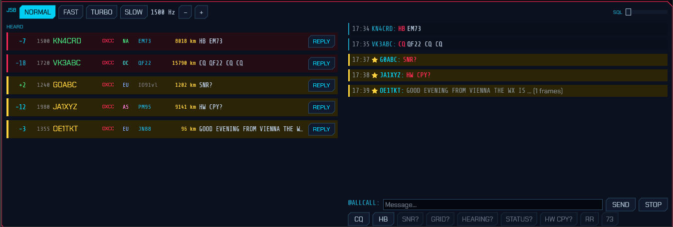
The panel. Under the header is the slot bar, the same one FT8 has (3.2.2) — how far through the current turn the clock is, dim cyan receiving and pink transmitting. Here it also shows what the speed buttons actually do: the bar takes six seconds to cross on TURBO and thirty on SLOW.
Stations heard are listed on the left in the same rows the FT8 decode list uses — report, frequency, callsign, what they would be worth (DXCC / BAND / GRID / NEW / DUPE), the country’s flag, continent, grid, distance, and the last thing they said — so a band you have learned to read in FT8 reads the same way here. Hovering a row brings up the full station card: entity, zones, bearing, and whether you have worked them before. A row addressed to you is boxed in gold; a heartbeat or a CQ, which are invitations, get the red CQ background.
The conversation is on the right, newest at the bottom, with anything addressed
to you marked ★. Each line reads sender · recipient · command · text —
OH8STN answering KN4CRD shows as OH8STN: KN4CRD HEARTBEAT SNR -02 — because
on a busy channel half a dozen stations answer the same beacon inside a minute
and the report alone does not say which of them was being answered. The heard
list summarises the same way. A message still arriving is shown greyed with a
frame count, because a half-received sentence should not read like a complete
one.
CLEAR RX, at the end of the button row, empties the conversation, and is
greyed while there is nothing in it. The heard list is left alone — it is a
separate pane, and it is what HEARING? is answered from.
Replying. Clicking a message — or a station’s REPLY button — aims the
composer at that station and drafts the reply the exchange expects. A heartbeat
or a CQ is asking “can anyone hear me?”, so it drafts a signal report; SNR?,
GRID?, STATUS? and HEARING? draft their answers; HW CPY? drafts a
report; RR and QSL draft 73; AGN? puts back the last thing you sent. It
is only ever a draft — it lands in the text box and you are free to rewrite it,
because most of JS8 is conversation and there is no standard answer to “good
evening from Vienna”. Free text drafts nothing and only selects the station.
Clicking a row rather than its REPLY button selects without touching what you
have already typed.
Sending. Nothing goes on the air until you press SEND or Enter. The
buttons under the conversation only fill the text box, so what is about to be
transmitted is always on screen first, and you can still change it. Beside the
send button is an estimate — 3f · 45s — of how many frames the message needs
and how long it will be on the air. Watch that number before you press send; it
is the thing newcomers to JS8 find most surprising. The message goes to whoever
the label in front of the box names: the selected station, or @ALLCALL when
there is none.
With a station selected, the query buttons draft a question for it: SNR?
for a signal report, GRID?, HEARING? for what it is copying,
STATUS? for its status message, HW CPY? for “how do you copy me”, and
RR / 73 to acknowledge and sign off. With nothing selected they are
greyed. CQ drafts a general call and HB a single heartbeat, and both
stay addressed to everyone even while a station is selected — selecting someone
never turns a CQ into a message for them. Typing CQ or HB yourself does the
same. CLEAR TO, past the rule at the end of the row, forgets the selected
station and puts the composer back on @ALLCALL; it is greyed while nothing is
selected.
Anything addressed to a callsign — typed, drafted or from a button — goes out as a JS8 directed frame, so the station at the other end sees a message meant for them rather than words that happen to name them. When the message opens with a command the mode knows, that command travels in the frame too; when it carries more than the frame can hold (a grid, a status line, a sentence) the rest follows as free text. The framing is byte-identical to JS8Call’s own, which is what the tests check it against. Relay and message-store commands are the exception: this station does not act on them, so it does not originate them either, and they go out as ordinary text.
On the map. Heard stations appear on the 3D globe (3D in the DISPLAY
row) exactly as FT8 decodes do, and the station the composer is aimed at gets
the contact arc from your QTH. Most JS8 traffic carries no locator — only
heartbeats, CQs and GRID replies do — so if callsign lookup is configured
(⚙ SETTINGS → Network → Uploads) the rest are resolved through it, one at a
time, and their grid is shown greyed to mark it as looked up rather than heard.
Because JS8 beacons every ten or fifteen minutes rather than every slot, a
station stays lit far longer here than in FT8.
Answering automatically. In ⚙ SETUP, Auto-reply answers SNR?, GRID?, STATUS? and HEARING? queries addressed to you or to @ALLCALL — with the answer, not just the acknowledgement: a report rides in the frame itself, and a grid or a status line follows it as text. This is what makes a JS8 station worth leaving switched on, and it is on by default. It never answers another station’s traffic, and never answers itself.
Heartbeat reply answers a heard heartbeat with a signal report, so the station beaconing learns who copied them and how well. It is off by default, and deliberately hedged about: a busy band carries a heartbeat every slot, and a station that answered all of them would flood exactly the band heartbeats exist to keep quiet. So it answers a given station at most once every 15 minutes, never while a multi-frame message is still arriving, and never while you have something of your own queued to send — an answer that waited behind a long message would carry a stale report anyway. A CQ is never answered automatically at all: it asks for a contact, and starting one is your decision.
Beaconing. Heartbeat transmits your callsign and grid on an interval so others know you are receivable — off, 10, 15, 30 or 60 minutes, the choices JS8Call offers. It is off by default: an unattended beacon is something you should choose, not something a mode switches on for you. HB AUTO in the panel header turns it on and off without opening SETUP, and the countdown beside it says when the next one goes out — a transmitter that keys itself should say so where you are already looking.
The first heartbeat is a whole interval away rather than immediate, so choosing an interval never keys the radio before you can change your mind. Each one is scheduled with up to a slot of jitter, because stations that share an interval and started together would otherwise collide on every beacon. Turbo does not beacon at all, and cannot acknowledge one: it is the local and VHF speed, and an unattended transmitter there spends a lot of a small band to reach nobody far away.
Where beacons go. Not on your working frequency. Heartbeats and their acknowledgements move to a free slot in the 500–1000 Hz sub-band, the same convention JS8Call follows: it is where stations watching for beacons look, and it keeps an unattended transmitter off somebody else’s QSO. The slot is chosen at the moment the beacon goes out — a beacon can wait behind a long message for minutes, and a frequency picked when it was queued would be somebody else’s by then. A slot counts as taken if anything was decoded within one signal width of it in the last half-minute (longer at Slow, whose transmissions are longer than that), and if the whole sub-band is busy the beacon takes whichever slot has been quiet longest.
So a beacon appears on the waterfall somewhere other than your transmit marker.
The panel header says where the last one went — HB 750 Hz beside the
countdown — so you can tell your own beacon from a stranger’s. If you would
rather keep everything you transmit in one place, ⚙ SETUP → Beacon frequency
→ Working freq switches it off.
Relayed messages and stored-message requests are decoded and shown, but this station will not act on them — forwarding traffic on someone else’s behalf is a decision for the operator.
3.10 RF Paint (spectrum painting)
Choose RFPAINT from the DIGITAL menu for RF Paint — a transmit-only mode that draws text and pictures directly onto a receiver’s waterfall. There is no decoder and no message format: the picture is the signal. Anyone watching their panadapter on your frequency simply sees what you paint, so it is a fun way to put a callsign, a grid, or a small graphic on the band.
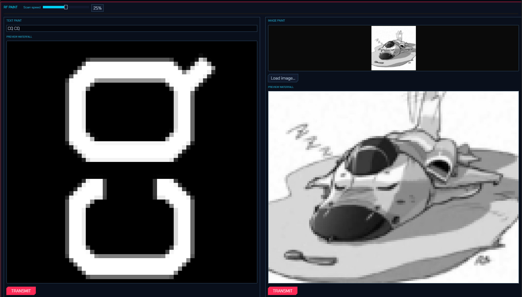
RF Paint transmits on USB and fills a 3 kHz audio band (about 300–3300 Hz), so it sits inside a normal SSB channel. It has no calling frequency — use it on a clear frequency where you are allowed to transmit, and tell the other station where to look. The panel has two side-by-side areas:
- TEXT PAINT — type a line of text and it is rendered as upright letters that scroll up the far station’s waterfall. The font size is fixed, so a longer message simply makes a wider banner (a longer transmission) rather than smaller letters. A live preview waterfall shows exactly how the text will look on the receiving end. Press TRANSMIT to send it.
- IMAGE PAINT — Load image… picks a picture (PNG or JPEG), which is reduced to a grayscale, contrast-stretched bitmap and shown in the image box. Its own preview waterfall shows how it will paint. Press TRANSMIT to send it.
Scan speed (the slider in the panel header) sets how fast the text or image is scanned onto the waterfall, from 100% (the base rate — fastest, shortest transmission) down to about 6%; 25% (the default) is a good compromise. Slower is more legible, because the receiver’s waterfall gets more scan lines to draw the picture — but it takes longer to send. A transmission runs from a few seconds to a couple of minutes depending on the length and the scan-speed setting.
While painting, a progress bar and a TX % readout track the transmission, and Abort stops it immediately. RF Paint goes through the normal transmit path, so the ham-band lockout and the usual transmit safety still apply. Because it is transmit-only, RF Paint receives nothing — you read other stations’ paintings on your own waterfall like any other signal.
3.11 WSPR (Weak Signal Propagation Reporter)
Choose WSPR from the DIGITAL menu. This is the one mode here that is not trying to make a contact. A WSPR transmission is 110.6 seconds of four-tone FSK six hertz wide, carrying a callsign, a four-character grid and a power level and nothing else, sent in a two-minute slot. It decodes about ten decibels below FT8 — well under the noise — and what comes out of it is a measurement of a path, not a message anybody sent you.
Selecting the mode puts the dial on the band’s WSPR frequency (14.095 600 MHz on 20 m, and so on — 3.1); every transmission in the world sits in the 200 Hz window 1400–1600 Hz above it. The receiver’s passband is narrowed to that window on purpose: with signals this weak, letting the QRSS beacons just below it work the AGC would cost you decodes.
The panel has three panes. On a wide screen the receptions run full height down the left and the map takes the top right, with the beacon’s status under it; narrower, the tab row picks one.
Receiving
The SPOTS pane lists receptions, newest first:
| Column | What it is |
|---|---|
← / → |
← a beacon this station decoded; → a station that decoded this one |
| Callsign, grid | The far end of the path |
| km | Great-circle distance from your locator |
| dB | Signal-to-noise in a 2500 Hz bandwidth, as WSPR reports it |
| power | What the beacon declared it was radiating |
The report colours are WSPR’s own scale, not FT8’s: green above −10 dB, cyan to −20, yellow to −26, and pink below that — because −25 dB here is a perfectly good path rather than a marginal one.
The list holds five thousand receptions — a night of a busy band, which is the span this mode is usually left running over — and the count beside the heading is what it is holding.
A slot takes seconds of work to decode, so the status pane says decoding… rather than leaving you to wonder whether the band is shut. The slot bar below the status header shows where in the two-minute cycle the beacon is, with the time left beside it: dim cyan listening, yellow decoding, pink on the air — where the mark shows where the 110.6-second burst stops. Every slotted mode has this bar; only WSPR’s turn is long enough to want a countdown with it.
The map, and the propagation heat on it
The MAP pane shows every station heard, fading over ten minutes — a WSPR beacon is heard every few minutes at best, so the FT8 map’s two-minute fade would leave this one blank almost always.
Each dot wears the colour of the band it was heard on, in the same palette the
propagation heat uses for ALL BANDS, with a key under the map naming them.
This is the one mode whose map routinely mixes bands: a beacon that hops puts
40 m, 20 m and 10 m stations on one picture, and one colour for all of them
cannot say which path opened. The key appears only when there is more than one
band up.
Above the map is the PROP button. It shades the map by where signals are
actually getting through; pressing it reveals the rest of the controls —
ALL BANDS or ONE BAND, which band, and the absolute path count the brightest
cell stands for. §7.8 explains what the
shading means. The same picture, with more control over it, is on the 3D globe.
Beside PROP is HEARD ME, which rings every station that reported hearing this station on the current band, from PSK Reporter, at the reporter’s own grid. It is the inverse of the coloured PSK spots: those are stations this radio is hearing, while these heard us. The query behind it is refetched hourly and covers the last hour, so it needs the PSK feed switched on under Settings → Spots and a callsign set on the General tab; the chip only decides whether the rings are drawn. Hover a ring for the reporter’s callsign, frequency, mode and the SNR they gave. Deliberately its own control rather than another spot colour: a dot at the receiver is a marker at the wrong end of a report, so these never appear in the SPOTS list or on the panadapter.
Beside it is NIGHT, which shades the night side of the map and the twilight either side of it — the grey line, the terminator where the low bands go long and the high bands close. The shading is drawn over the propagation heat when PROP is on, so a band that is dead because the Sun is down reads that way, and under the coastlines so the geography stays legible. Like PROP it is off by default: it is scenery rather than something to leave switched on over a decode list, and it is drawn whether or not PROP is. The Sun’s position is the same one the band conditions are read from, so the shade and the “day”/”night” a verdict calls a band cannot disagree.
NIGHT is on every flat map, and the one switch turns it on for all of them: the operating panel’s FT8/FT4/FT2, WSPR and JS8 maps, and the ADS-B, AIS, APRS and HFDL maps — the last four carry their own NIGHT chip above the chart. Where a map has no chip row of its own (the four decoder maps), the chip sits just above it. Switching it on anywhere lights the same terminator everywhere.
Drag the strip under the map to resize it against the status pane.
Transmitting
Off until you ask for it: selecting a mode is not consent to put a carrier on the air.
Everything is in the STATUS pane; WSPR has no separate setup dialog.
- TRANSMIT is the switch and the setting at once:
OFFis receive-only, and10% / 20% / 33% / 50%is the fraction of two-minute slots this station beacons in. 20% is the convention — enough to be heard, sparse enough that a hundred beacons can share two hundred hertz. The slots are drawn from your callsign, so two stations running sdroxide do not pick the same ones. - POWER is what you actually radiate, in watts. Only the nineteen levels WSPR’s fifty-bit message can name are offered — 1 mW through 1 kW in 1-2-5 steps — because the figure goes out on the air and everyone who hears you judges the path by it. An optimistic number here makes their measurements wrong as well as yours.
- ROAM picks a different offset inside the 200 Hz window for every transmission. On by default: two hundred hertz shared by everyone only works if nobody parks in the middle of it.
TRANSMIT, POWER and the band-hop settings belong to the radio they are set on. With several radios open, each beacons — or doesn’t — on its own say: switching one on leaves the others as they were, and a radio added later starts with its beacon off.
Your callsign and grid come from the General tab of Settings — the same identity the rest of the program reports under. The panel says which it is transmitting as, and says so in yellow if either is still blank.
WSPR’s message carries a plain callsign and a 4-character locator and has
room for nothing else. A longer locator is simply shortened — JN47cb goes out
as JN47, which is what the extra precision means anyway — and the panel shows
which form it is transmitting as. A compound callsign (PJ4/K1ABC) genuinely
cannot be sent: it needs a message layout this station cannot encode, and the
panel says so rather than transmitting something that is not you. Receiving is
unaffected either way — all three message types decode.
One receive limitation worth knowing: a Type-3 message spends its callsign
field on a 15-bit hash so it can carry a six-character grid instead of four.
That hash is not invertible, and sdroxide cannot currently compute it either, so
such a station is listed as <#0a3f7> rather than by name. Its grid arrives
in the clear, so the path is real, the map places it and the propagation heat
map counts it — only the name is missing. Those spots are deliberately not
uploaded to WSPRnet: posting a placeholder would put a station that does not
exist into a database everybody reads.
Band hopping
BAND HOP moves the dial from band to band between slots, so one receiver samples the whole spectrum instead of one slice of it. A row of band buttons appears under it when it is on, for choosing which bands the cycle visits. Turning the VFO yourself pauses it and says so — a beacon and its operator fighting over the dial is the one thing this must not do — and applying the setup again resumes it. It never moves under a transmission, and a band the radio cannot reach is skipped silently.
WSPRnet
- UPLOAD sends what you decode to https://wsprnet.org. On by default: it puts nothing on the air, and reporting what you hear is what makes a WSPR receiver part of the network rather than a private curiosity. A slot that decoded nothing is reported too, which is how the network tells a shut band from a receiver that was switched off.
- WHO HEARD ME polls wsprnet.org for reports of your own callsign. WSPR has
no acknowledgement of any kind, so this is the only way a beacon learns
anything about its own reach. Those reports appear in the list with a
→and place the reporter on the map — the far end of the path, which is the end worth drawing.
Both are on the Spots tab of the Settings dialog as well as the panel, and both use the callsign and grid from the General tab.
3.12 APRS
Choose APRS from the DIGITAL menu. This is the Automatic Packet Reporting System: 1200 baud AX.25 on one shared FM channel per region, carrying positions, weather, telemetry, objects and short messages. It is not a QSO mode — almost everything on the channel is a broadcast that nobody answers — so the panel is a map, a station list and a message pane rather than a sequencer.
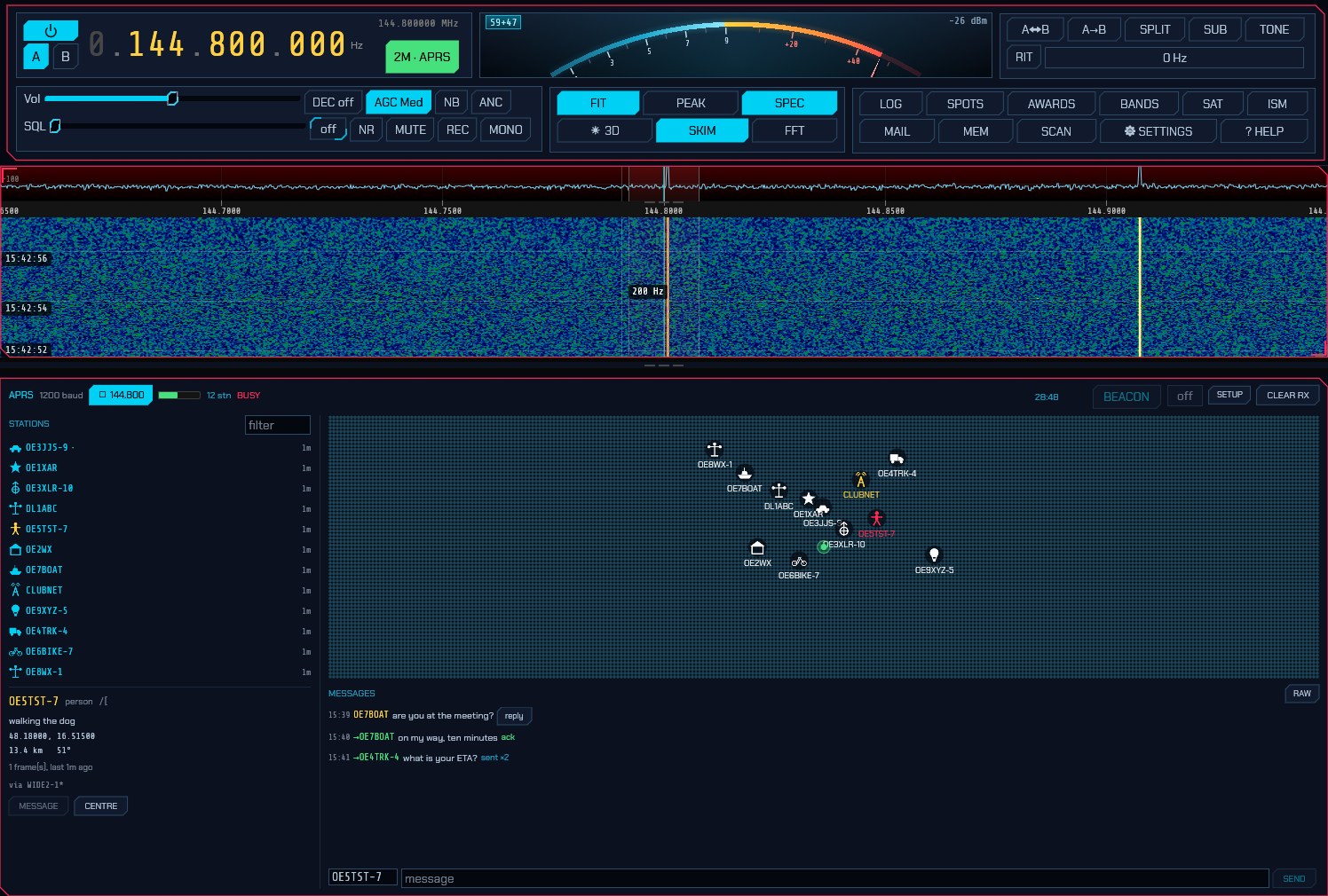
The frequency is chosen for you. APRS is a channel, not a band segment, and which channel depends on where you are. Selecting the mode tunes to your region’s:
| Region | Channel |
|---|---|
| 1 — Europe, Africa, Middle East, Northern Asia | 144.800 MHz (70 cm: 432.500) |
| 2 — the Americas | 144.390 MHz (70 cm: 445.925) |
| 3 — Asia-Pacific | 145.175 MHz (Japan and China: 144.640; South-East Asia: 144.390) |
Set your region under Settings → General. If the dial is already on any region’s APRS channel — you tuned Japan’s 144.640 by hand — it is left alone, and so is any move you make once you are in the mode. The ⇵ FREQ button beside the frequency lists the other regions’ channels.
Unlike the slotted modes, the waterfall is not narrowed to the channel. APRS occupies about 12 kHz of a 2 m band you have every reason to be watching — the repeater outputs above it, the simplex calling frequency below — so the view opens on 300 kHz around the channel and zoom and pan stay live from there. It is re-framed only when you change mode or retune far enough to take the channel off the screen.
The panel
The panel header carries the channel itself: the receive level, how many stations are on the map, whether the channel is busy, and — on the right — the beacon interval and the buttons.
STATIONS is everything heard, most recent first: a table of icon, callsign, whatever the station last said, and how long ago. The bar down the left edge of each row is green for a station heard direct — no digipeater repeated it — which on a channel where almost everything is digipeated is how you tell who is actually within range; amber marks an object somebody else put on the map, and grey one that has been cancelled. Type in the filter box to narrow the list by callsign or comment. Clicking anywhere on a row selects that station.
Click a station and its card opens underneath: what it is, what it said, where
it is, how far away and on what bearing, its course, speed and altitude, its
weather if it sends any, how many frames it has sent, and the digipeater path
the last one came through (a * marks a digipeater that actually repeated it).
Selecting a station also addresses the message box to it.
The map places everything with a known position, on the same coastlines, borders, rivers and cities as the FT8 panel’s (the world map) — which matters more here than there, because an APRS map is usually zoomed in far enough for a river and a town name to be what tells you where a station is. It auto-frames what it can hear; drag to pan, wheel or pinch to zoom, and double-click to hand it back to the auto-fit. Icons fade as a station goes stale, over the same window the station list keeps, so a position that has not been refreshed in an hour visibly is an hour old. Anything that has moved leaves a trail behind it. A station that reported an ambiguous position — the protocol lets a sender blank out the last digits of its coordinates on purpose — is drawn inside the square it actually described rather than as a point in the middle of it.
Objects and items (a net control point, a storm, an event, put on the map by some other station) are drawn in a different colour and named after themselves. An object its owner has cancelled is greyed rather than removed: an object vanishing without trace looks like a receiver problem.
MESSAGES is the one part of APRS that is a conversation. Pick a station, or type a callsign in the to box, write in the message box and press SEND or Enter. A message carries an identifier, so the far end acknowledges it and sdroxide retries until it does — five attempts, thirty seconds apart to begin with and doubling, because the far end is usually a mobile behind a hill rather than somebody who is slow to answer. The mark beside your message says where it has got to:
| Mark | Meaning |
|---|---|
… |
Queued, waiting for the channel to clear. |
↑ / ↑3 |
On the air, waiting for an acknowledgement (and which attempt). |
✓ |
Acknowledged by the far end. |
✗ |
Refused, or no answer after every retry. |
Messages addressed to you are answered with an acknowledgement automatically —
switch that off under Setup if this station has no antenna on transmit.
Bulletins (addressed BLN…) are shown and never acknowledged: a hundred
stations acknowledging one bulletin would take the channel down. Other people’s
messages stay out of this pane and go in the raw log instead.
RAW swaps the pane for every frame on the channel as it arrived, with what
the decoder made of each — position, weather, message, object, or the
reason it made nothing of it. That last one is how you find out that something
on your channel is sending a format this build does not read.
Setup
SETUP in the panel header opens the APRS settings.
- APRS call — the callsign this station beacons under, with its SSID:
-9for a car,-10for an I-gate,-5for a phone,-7for a handheld. Leave it empty and your station callsign from Settings → General is used as it stands; the field exists because an APRS station conventionally carries an SSID that distinguishes it from the operator, not because you should have to type your callsign twice. The dialog shows what will actually go on the air underneath it. With neither filled in nothing is transmitted at all — not a beacon, not a message, not an acknowledgement, because an APRS frame with no callsign in it is an unidentified transmission — and the panel says so in red rather than leaving you pressing a button that does nothing. - Symbol — what you are, as a row of icons for the ones an amateur station
usually is, with the two characters editable beside them for the other 170. A
digit or a letter in the first position is an overlay, drawn on top of the
icon:
Sover a digipeater is a digipeater that also runs an I-gate. - Path — how far you ask to be repeated, and the most consequential setting
on the whole channel.
WIDE1-1,WIDE2-1— one local fill-in hop then one wide one — reaches almost anywhere. Every extra hop multiplies the transmissions the whole network makes on one shared frequency, so a long path does not get you further out; past three hops it stops other people being heard. sdroxide says so in the dialog if you ask for one, and transmits it anyway: local practice varies, and a path that is wasteful in a European city is reasonable in the outback. - Position — from your Maidenhead locator by default, reported with the ambiguity a locator actually has (a six-character one is a couple of kilometres across, and saying so is honest). The Latitude and Longitude boxes below it always show what will go out; while the locator is in charge they are greyed and read from the locator. Untick From my grid and they become yours to type — decimal degrees, negative for south and west, and they start from wherever the locator had you so you are never editing from zero.
- Comment — free text sent with every beacon, up to 43 characters.
- Beacon — minutes between beacons, the same setting as the interval in the
panel header.
off, which is the default, never beacons: selecting a mode must not put a station on the air. Thirty minutes is the convention for a fixed station once you turn it on, oftener for a moving one, and the first goes out one interval from now rather than immediately. Compressed sends the compact position format — a third of the air time and more precise — which every receiver since the 1990s reads. - Messages → Acknowledge — answer messages addressed to you. An acknowledgement is a transmission this station makes without you asking, so a receive-only setup should turn it off; the beacon then stops claiming to be reachable too.
- TX delay — flags sent ahead of every frame so the far end’s modem hears the carrier and locks its clock before the data starts. It has to outlast everything between pressing transmit and actually radiating: sdroxide alone spends 165–240 ms of it on a CAT rig, and a radio taking its audio over a network buffers more on top of that. Too little and the far end never locks — the transmission is on the air and nothing decodes it. Shared with the packet mode, since it is a property of the radio rather than of the protocol.
-
TX audio — APRS’s own deviation, in dB below full scale, into a radio that modulates the audio we hand it: a CAT rig on its sound card, a FLEX, an Icom on its network port. A radio sdroxide modulates itself always gets full scale, because there the modulator and Drive own the level instead.
An FM transmitter turns audio level into frequency swing and has no ALC to catch it: 1200 baud packet wants about 3 kHz where voice wants 5, so full scale into a data input set for voice over-deviates. An over that over-deviates sounds completely normal to anyone listening and decodes for nobody, so this is the first thing to try when your frames are clean and still nothing acknowledges them. The radio’s own input level is the other half of it.
The level belongs to APRS alone — every mode keeps its own, so a deviation set for 1200 baud never lands on your FT8. The same control is on the transmit strip, in the Mic rail’s place, where you can reach it without opening this window; 2.10 has the full description and the sideband half of the story.
- Keep stations — how long a station stays on the map after it was last heard, and what the map’s fade is measured against.
BEACON in the header sends one position report now, without waiting for the
timer, and the box beside it is how often to beacon unattended — off by
default. Both go through the channel-access rules like everything else: they
wait for the channel to be clear, so a busy channel delays a beacon rather than
doubling on somebody.
When nothing is decoding
The bar beside 1200 baud is the audio actually reaching the modem, and it is
the first thing to look at. Flat means nothing is arriving at all — the radio’s
data output is not the one sdroxide is listening to. It lights green while the
modem hears a carrier, and BUSY appears beside it for the same reason.
If the bar is moving and the map stays empty, switch the message pane to RAW
and watch the counts beside it. Frames arriving and failing their check sequence
(N bad) mean the modem is reading the channel and the signal is marginal.
Nothing at all, with a healthy level, usually means one of:
- the squelch is closed. A transceiver’s FM squelch takes a moment to open and eats the start of every burst, which is the whole preamble. Open it fully, or take the audio from the radio’s data socket, which is not squelched.
- the audio is from the loudspeaker path rather than the data socket, and something in between — a tone control, a de-emphasis network, an audio processor — is doing to 2200 Hz what it does not do to 1200 Hz.
- the rig is not in FM. APRS is an FM channel; selecting the mode commands FM over CAT, but a radio that is not being commanded (no CAT cable, or a control port nothing answers on) has to be put in FM by hand.
- the radio is not in its data mode. sdroxide asks for FM-D (or whatever the rig calls FM with DATA on) over CAT, because plain FM puts the microphone path’s speech processing and pre-emphasis on the way out — and pre-emphasis alone tilts the 1200 and 2200 Hz tones about 6 dB apart, which sounds like packet to a listener and is unreadable to a modem. A rig nothing is commanding has to be put in it by hand.
If your transmissions are the ones nobody can decode, the audio itself can be ruled in or out without another operator. Record an over (the REC button captures transmit audio as well as receive), extract the right-hand channel, and run it through an independent decoder:
ffmpeg -i <recording>.mp3 -af "pan=mono|c0=c1" -ar 44100 tx.wav
atest tx.wav          # from Direwolf
A frame printed there is a frame that left sdroxide correctly, and anything still wrong is between the radio’s modulation input and the air — the TX audio level above, the radio’s own input level, or its data-mode setting.
The log line to look for
is digital transmit audio is being rate-matched to the radio. Some radios
receive at one sample rate and transmit at another — an Icom on its 12 kHz IF
output receives a stream decimated to 24 kHz while taking transmit audio at 48 —
and the modems are built for the receive rate, because a digital mode keeps one
clock for both directions. sdroxide rate-matches the transmit audio for you and
says so once per over; before it did, a packet burst went out at exactly twice
its baud rate, which is structurally perfect and readable by nothing.
What is decoded
Everything a station is likely to send: uncompressed and compressed positions, Mic-E (the format every commercial APRS radio transmits, which hides half the position in the AX.25 destination address), objects and items, status reports, Maidenhead grid reports, telemetry, queries, weather both attached to a position and standing alone, and messages, acknowledgements, rejections and bulletins. Weather is converted from the miles per hour, degrees Fahrenheit and hundredths of an inch the protocol carries.
3.13 ADS-B (aircraft on 1090 MHz)
Choose ADS-B from the end of the DIGITAL row. It sits apart from the rest of that row all the same: there is no QSO to work and no transmitter, only a signal to point the radio at. Every civil aircraft in the sky transmits its identity, altitude, velocity and position on 1090 MHz, twice a second, in clear and with a checksum. The panel is a target list on the left and a radar picture on the right.
The frequency is chosen for you. There is exactly one ADS-B channel, worldwide. Selecting the mode tunes to 1090.000 MHz unless the receiver is already looking at it, and the 1090.000 button in the panel header puts it back if you wander off.
What you need
An antenna for 1090 MHz, on the right socket. This matters more than anything else on this page. A quarter wave at 1090 MHz is 69 mm long, and an HF wire or a discone is tens of decibels deaf up there. On a receiver with separate inputs — the RX-888’s HF and VHF sockets, for instance — 1090 MHz arrives only through the VHF one, and an antenna on the other socket produces exactly the symptom you would expect from a broken decoder: an empty list, or one or two aircraft that come and go. Sixty-nine millimetres of wire in an SMA plug, against a window, is usually good for a hundred kilometres.
Turn any input attenuation off, and switch the bias tee on if your antenna or preamplifier wants it. Attenuation that is right on a crowded HF band is simply loss here.
A stream of at least 2.4 Msps at 1090 MHz. Mode S is a megabit a second and every bit is two half-microsecond chips, so this is about how many samples land inside a chip:
| Stream | What happens |
|---|---|
| below 2 Msps | Refused. There is not one sample per chip; there is nothing to slice. |
| 2.0 – 2.4 Msps | Runs, and says it is degraded. A chip and a sample are the same width, so a burst arriving out of step with the sample clock has chips split equally across two samples that then read the same. Strong aircraft decode; the rest are lost. |
| 2.4 Msps and up | Full performance. Every arrival phase decodes. |
An RTL-SDR at its default 2.4 Msps is the classic receiver for this and sits exactly on the line. So do an Airspy, a HackRF, an SDRplay, a Pluto and a LimeSDR. On a receiver whose window width you choose — the RX-888’s panadapter width setting, for example — pick 4 MHz or more; SDRoxide keeps whatever it is given, up to 9 MHz, because more samples per chip is strictly better here and nothing is gained by throwing them away.
What will never work is a transceiver handing over demodulated audio, or a front end decimated below 2 Msps. In each case the panel says so in a sentence rather than showing an empty list you would have to guess at.
The aircraft list
One row per aircraft, keyed on its ICAO address — the 24-bit number assigned when it was registered, unique worldwide and unchanging.
| Column | What it is |
|---|---|
| CALL | The flight identification it is broadcasting. Empty for the first few seconds: an aircraft sends its position twice a second and its callsign every five, so the address arrives first. The row shows the address until the callsign does. |
| ICAO | The address, in hex, once there is a callsign to distinguish it from. |
| ALT | Altitude. Flight level above 18 000 feet (F350), hundreds of feet below it (045), and GND on the ground. |
| GS | Ground speed in knots. |
| TRK | Track over ground, degrees true. |
| V/S | Rate of climb or descent, feet per minute. |
| SQK | The squawk — the four-digit code the crew set for air traffic control. Only some frames carry it; see below. |
| KM | Range from your station. Shown once My grid is filled in (§3.1). |
| AGE | How long since anything at all was heard from it. |
The buttons above the list sort it; clicking the one already selected reverses the order. Clicking a row opens the full card below it — everything the table has no room for, including geometric altitude, turn rate, signal level and the last frame as hex — and selects the aircraft on the map. CENTER in the card puts it in the middle of the picture.
A greyed row is an aircraft that is still being heard but has not reported a position for ten seconds. It stays on the list and comes off the map; see below.
The radar picture
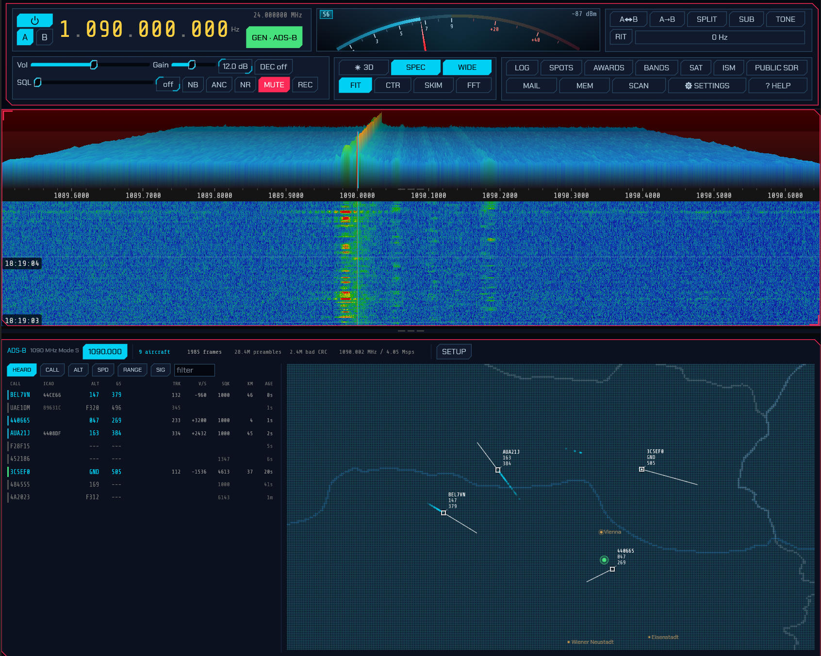
Standard surveillance-display symbology, and each part of it is telling you something:
- A white square is an aircraft. Everything up there is an aeroplane, so a symbol that said which kind would be saying nothing; the square stays the same size at every zoom, so a glance across a busy sector reads as one class of thing. A dot inside it means the aircraft is on the ground.
- History dots behind it are where it has been. Their spacing is its speed and their curve is its turn, which is how a controller reads both before reading any number on the screen.
- A leader line ahead of it is where it will be in a minute. The length is the speed: two aircraft with equal leaders are going equally fast, at any zoom. It bends when the aircraft is turning.
- The data block beside it is the callsign, the altitude and the speed — the order every radar display in the world puts them in. It sits up and to the right, or at another corner where the edge of the map or a neighbour is in the way. On a crowded picture a block with no room anywhere is left off rather than drawn over another block or target — aircraft on the ground give way first — while the selected target, the one under the pointer and any squawking an emergency always keep theirs.
Drag to pan, scroll to zoom, double-click to reframe. Your own position is marked once My grid is set.
A target with a stale position is not drawn at all. Past the timeout it comes off the map — square, dots and block together — while staying on the list, greyed. It is deliberately not faded instead: a dim square at a half-minute-old position is still a claim about where an aeroplane is, made in the same ink as the true ones, and the map is the one place with no room for a hedge.
Setup
SETUP in the panel header opens the decoder’s own settings.
| Setting | Default | What it does |
|---|---|---|
| Drop from map after | 10 s | Without a position report, the target leaves the map and its row greys. |
| Drop from list after | 60 s | With nothing heard at all, the aircraft is forgotten. |
| Trail length | 40 points | How many past positions are kept and drawn. |
| Speed vector | 1 min | How far ahead the leader line reaches. Zero switches leaders off. |
| Track at most | 300 aircraft | A ceiling, so a busy sector cannot grow without bound. The longest-silent go first. |
What is decoded, and what is believed
Two kinds of transmission arrive on this channel, and SDRoxide treats them very differently.
Extended squitters (downlink formats 17 and 18) are what an aircraft broadcasts on its own: identity, category, barometric and geometric altitude, position, velocity, and its emergency state. They carry a plain 24-bit check sequence, so a frame either checks out or it does not. These prove themselves.
Surveillance replies (formats 0, 4, 5, 16, 20 and 21) are answers to a ground radar’s interrogation, and they carry an altitude or the squawk. Their check sequence has the aircraft’s address mixed into it, because the interrogator already knew who it had asked — which means that to a receiver listening passively there is nothing in the frame to check it against. Taken alone, any 56 bits of noise “decode” to some address.
So SDRoxide accepts one only when the address it yields already belongs to an aircraft heard from a verified squitter, recently. That is what buys you the squawk column and the faster altitude updates without inventing aeroplanes. It is also why a squawk appears for some aircraft and not others: it depends on whether a radar is interrogating them where you can hear the answer.
No error correction. Other decoders will flip a bit, or two, looking for a frame that checks out; it recovers some weak transmissions and it also invents aircraft, and an invented aircraft on a map looks exactly like a real one.
Two encodings are deliberately not decoded, and an aircraft using either shows no altitude rather than a wrong one: the 100-foot Gillham encoding, used above 50 175 feet and by a few older transponders, and the metric encoding, which the standard provides for and nothing transmits.
Trying it without an aerial
There is a signal generator in the source tree that synthesises a sky:
cargo run --release -p sdroxide-adsb --example adsb_iq -- /tmp/sky.iq
sdroxide --file /tmp/sky.iq --rate 2400000 --freq 1090000000 --mode ADS-B
Six aircraft at descending signal levels, flying. It proves the whole chain works; it does not prove the decoder works on air, because the transmitter and the receiver were written by the same hand.
For that there is a second test, against real off-air recordings made by somebody else with somebody else’s hardware, checked against what their decoder finds in them. Point it at a checkout of rsadsb/dump1090_rs:
SDROXIDE_ADSB_IQ=/path/to/dump1090_rs/test_iq \
  cargo test -p sdroxide-adsb --test reference_corpus -- --nocapture
SDRoxide finds all fourteen messages in those three captures, and nothing the reference does not also find.
If nothing is decoding
Record a few seconds and look at what the receiver actually heard:
sdroxide --server --freq 1090000000 --mode ADS-B --record-iq /tmp/air.iq
cargo run --release -p sdroxide-adsb --example adsb_replay -- /tmp/air.iq <rate>
The summary line at the end distinguishes the two failures. Preambles but no frames means the correlator is triggering on noise and nothing is checking out — there is no signal, and the antenna is the place to look. No preambles either means the receiver is not even seeing bursts. A working setup shows strong aircraft 30 dB or more above the noise floor; if the loudest thing in the capture is 10 dB above it, no decoder will find anything in it.
3.14 NAVTEX
Choose NAVTEX from the DIGITAL menu. It is the maritime safety broadcast every coast station in the world sends: navigational and meteorological warnings, search-and-rescue bulletins, ice reports, pilot notices.
Receive only, and deliberately. The service belongs to coast stations and sits next to distress traffic; an amateur transmitting on it would be putting out safety information nobody may act on. There is no transmit half of this panel and no callsign to set.
The channels. The band buttons are the three services: 518 kHz (international, always English), 490 kHz (national language, so whatever your nearest coast station broadcasts in) and 4209.5 kHz (tropical). What they tune is 1.7 kHz below the channel, because the quoted frequency is the assigned one — the centre of the two tones — and a receiver in upper sideband has to sit below it to put them at 1615 and 1785 Hz. That arithmetic is done for you, and the readout still says where the signal is. A dial a few hundred hertz off is fine too: the decoder follows the tones up to ±350 Hz away.
A dial that is a little off still decodes. The receiver tracks the tones itself, so a readout a few hundred hertz out — a rig that will not set exactly, or one of the tuning figures that rounds differently in different publications — is pulled in over the first second or so instead of returning nothing. It is not a reason to be careless: a mistuned signal still carries more errors than a clean one, and past about ±350 Hz the pull-in gives up.
NAVTEX is a timetable, not a conversation. This is the single thing newcomers miss most, and it looks exactly like a broken decoder: each coast station sends for ten minutes, once every four hours, on its own schedule. Most of the time nothing is transmitting — a silent panel is the normal state, not a fault. You have to be listening when your nearest station is due. The schedules are published (search “NAVTEX broadcast schedule” for your region); there is nothing to set here, only to know. And 518 kHz is a night band: daytime you will usually hear little or nothing, which is also not a fault.
What you see. Two panes:
- MESSAGES — one entry per message, newest first, headed by the four characters the service identifies it with: the transmitter (a letter the NAVAREA co-ordinator allocated), the subject, and a serial number. Navigational warnings, meteorological warnings and search-and-rescue bulletins are shown in red — a ship’s receiver is not allowed to filter those three out, and sdroxide does not offer to either. A message that was cut short, or that lost characters, says so under its heading.
- READING — the message selected, or the one arriving. Monospaced and unwrapped, because a NAVTEX message is laid out in columns by the station that sent it and reflowing it destroys the only formatting it has. With nothing selected and nothing arriving it shows everything decoded, message or not, which is the honest view when a header has been missed.
The time a message states is shown beside its heading, where the body names
one — 1200 UTC, 0900Z, 06:30 UTC. It is read out of the text, not a field
of the format: a gale warning states when it was issued, a station’s time
broadcast is an ordinary message that happens to carry a clock reading. Only a
four-digit time marked as one is taken, so a position (5103N 00109E) or a
serial is not mistaken for a time of day. It is shown for the reader and
nothing else — sdroxide never sets the system clock from it.
A station repeats itself, and that is the point. Each transmitter has a ten
minute slot every four hours, and it sends the same messages again on the next
one. sdroxide keeps one entry per message — a repeat replaces the copy already
held when it is better, meaning it reached its NNNN where the first did not, or
lost fewer characters. So a warning that faded halfway through fills itself in
over the next few hours instead of appearing four times half-copied.
The two numbers beside SYNC are what the mode’s error correction actually
did. NAVTEX has no checksum: every character is sent twice, five character times
apart, in an alphabet where exactly four of seven bits are marks — so a single
bit error makes a code that cannot exist, and the repeat is what replaces it.
Repaired counts the characters taken from the repeat and lost the ones where
both copies were bad; a lost character stands in the text as *, marked rather
than hidden, because half a gale warning has to look like half a gale warning.
REV swaps the mark and space tones, for a signal received on the other sideband. Off is upper sideband on the channel, which is what every published tuning instruction for the service says.
If it decodes as garbage, it is almost always the tuning. NAVTEX is quoted as a channel, and this receiver sits 1.7 kHz below it in upper sideband — so the 518 kHz service is read with the dial on 516.300, not 518 or 519. The band buttons (518 / 490 / 4209.5) set that for you; a rig tuned by hand wants 516.300 kHz USB. A steady, strong signal that still reads as nonsense is usually landing on the wrong sideband: press REV. And a band with no coast station transmitting — 518 kHz is busy mostly at night — is not a decoder fault.
3.15 VDL2 (what the aircraft are saying)
Choose VDL2 from the end of the DIGITAL row. VHF Data Link Mode 2 is the datalink airliners and ground stations exchange ACARS over — company messages, position reports, weather requests, fuel and arrival figures, and the link management that carries them — on fourteen 25 kHz channels between 136.650 and 136.975 MHz.
Receive only. These are commercial aeronautical channels. There is no transmit half of this panel and no callsign to set.
The frequency is chosen for you. Selecting the mode tunes to 136.8125 MHz, the middle of the group, and the decoder places its own window from there to take in as many of the fourteen channels as your receiver can reach. The 136.8125 button in the panel header puts it back if you wander off.
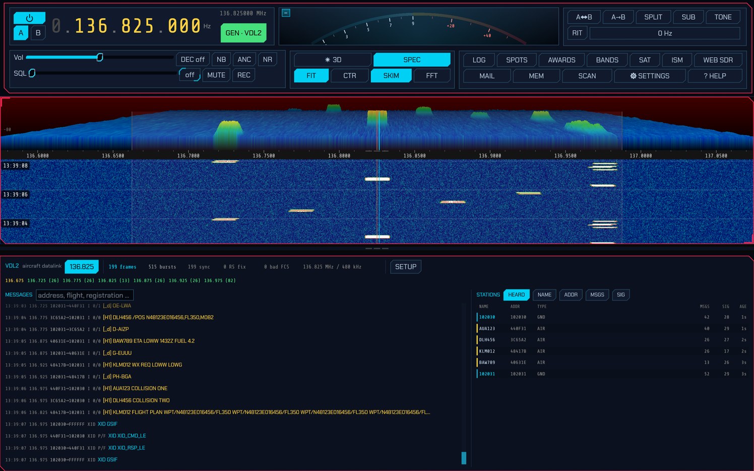
The waterfall above the panel is the whole group at once, so the transmissions are visible as short bright dashes on whichever channel carried them — which is worth a glance before reading a single counter, because a band with no dashes in it has nothing for any decoder to find.
What you need
An antenna for the air band, outdoors and with a view. This matters more than anything else on this page. VDL2 is line-of-sight VHF: an aircraft at cruise is receivable a couple of hundred kilometres away, and a ground station only as far as the horizon. An indoor wire will hear the FM broadcast band perfectly well and nothing at all up here — the two facts are not related, and the first is not evidence for the second. A quarter wave at 136.8 MHz is 55 cm.
Turn any input attenuation off, and be careful with gain: the FM broadcast band 40 MHz below is enormous by comparison, and a tuner wound up to its limit will be overloaded by it rather than made more sensitive. If the whole air band rises together as you add gain, that is what has happened.
A stream of at least about 470 kHz. The plan is 350 kHz wide, and a receiver’s outer edges are where its own filter is rolling off, so a window has to be about a third wider than the plan to hold all of it:
| Stream | What happens |
|---|---|
| below 34 kHz | Refused. There is not room for one channel. |
| 34 – 467 kHz | Runs, and says which channels it cannot reach, and between which two frequencies the ones it does reach lie. The window slides to take in as many as it can. |
| 467 kHz and up | All fourteen channels. |
Almost any receiver clears the last row: an RTL-SDR at its default 2.4 Msps, an Airspy, a HackRF, an RX-888, a Pluto, an SDRplay. What matters far more is the aerial.
The channels
Every 25 kHz slot from 136.650 to 136.975 MHz, all listened to at once:
| Channel | Assigned to |
|---|---|
| 136.650 | An airport’s ground station — the North American assignment. |
| 136.675 | An airspace ground station, alongside the European twelve until 2027. |
| 136.700, 136.725, 136.750, 136.775, 136.800 | Airspace ground stations. |
| 136.825 | An airport’s ground station. |
| 136.850 | An airspace ground station. |
| 136.875 | An airport’s ground station. |
| 136.900 | An airspace ground station. |
| 136.925 | An airport’s ground station. |
| 136.950 | An airspace ground station. |
| 136.975 | The Common Signalling Channel — the one frequency in use worldwide, where every link starts. The one to keep if you keep only one. |
“Airport” and “airspace” say which kind of ground station the slot is assigned to: one serving the aeroplanes on and around an aerodrome, or one serving an area from a remote site. Both carry aircraft as well, so neither label is a direction of travel — the published tables mark these GND and AIR, which reads backwards the first time you hear an airport’s ground station on an “AIR” channel.
Which of them are busy is a local matter, and not one this list can answer for you: a plate that is silent in one country is the only busy one in another. Leave them all on unless you have a reason not to.
The message log
One line per frame decoded, newest at the bottom, the way a conversation is read.
| Column | What it is |
|---|---|
| Time | When the frame was decoded, UTC. |
| MHz | Which of the fourteen channels it arrived on. |
| From → To | The two 24-bit addresses. For an aircraft this is its ICAO address — the same number its ADS-B squitters carry, so an aeroplane heard on both bands is recognisably one aeroplane. |
| Type | The link control field: I for information (with its sequence numbers), RR/REJ and friends for flow control, UI for a broadcast, XID for link management. |
| Message | The ACARS label and text, the kind of XID exchange, or — for a payload SDRoxide does not read — what it appears to be and how long. |
Click a line to open the full card below it: every field, the signal figures, and the frame as hex. The filter box searches an address, a registration, a flight identification, an ACARS label or the message text, and it filters the station list beside it at the same time.
HOLD stops the log where it is. Near a busy airport the next transmission arrives before you have finished reading the last one, and this is the answer to that: the list stops moving and stays where you scrolled it, while the decoder, the counters and the channel strip carry on behind it. The chip counts what has arrived meanwhile — HELD +23 — and letting go shows all of it.
Colour says what kind of traffic it is. Yellow is ACARS — the messages with words in them. Cyan is XID, which is aircraft and ground stations arranging links. Grey is a frame this pass does not read, or a supervisory frame with no payload at all.
The station list
One row per address heard, which is who is out there — a scrolling log makes that surprisingly hard to see on a busy channel.
| Column | What it is |
|---|---|
| NAME | The flight identification, or the registration, or the address. The first two arrive only when the station sends an ACARS block, so a row showing an address is normal rather than broken. |
| ADDR | The 24-bit address in hex. |
| TYPE | AIR for an aircraft, GND for a ground station, ALL for a broadcast address. |
| MSGS | Frames from this station this session. |
| SIG | Signal-to-noise of the last one, dB. |
| AGE | How long since anything was heard from it. |
Clicking a row filters the log to that station.
The channel strip and the counters
The row under the header is the fourteen channels. Green means frames have come out of it, yellow means transmissions have been detected and none has decoded, and grey means it is not being listened to — hovering says which of the two reasons that is, and what the channel is assigned to.
A channel that shows nothing at all is the ordinary case, not a fault. Which of the fourteen carry traffic depends entirely on where you are: in most of Europe it is a handful of them, in North America usually 136.975 and one or two others, and the rest of the raster is somebody else’s local plan. Each channel is measured in its own bandwidth, so a strong station 25 kHz away is not counted as a burst here — a channel with a count on it really did hear something on that frequency. The counters beside them are arranged in the order the decoder fails in, and the first one that stops counting names the problem:
| Reading | What it means |
|---|---|
| no bursts | Nothing is rising above the noise. The aerial, or a receiver that is not looking here. |
| bursts but no sync | Something is on these channels and it is not VDL2. |
| sync but no frames, with HDLC bad climbing | The transmission header is being read and the frame inside it is not. That is SDRoxide’s fault rather than the band’s, and worth reporting. |
| sync but no frames, with both low | Real VDL2 arriving too damaged to decode — a weak signal or the wrong aerial. |
| bad FCS climbing with frames | Frames arriving damaged. A few among many is ordinary at the edge of coverage. |
One thing not to read too much into: SDRoxide’s Reed-Solomon parameters do not match what is actually on the air, so the error correction repairs nothing and every frame you see arrived intact and passed its own check sequence. That is why there is no “blocks repaired” counter to watch. It costs the marginal frames a stronger receiver would have rescued; it costs nothing in wrong ones, because the check sequence is what admits a frame either way. If you have a recording of a band SDRoxide decodes poorly, that is the thing most likely to fix it.
Setup
SETUP in the panel header opens the decoder’s own settings.
| Setting | Default | What it does |
|---|---|---|
| Channels | all fourteen | One downconverter each. Switching one off saves a little processor time; it does not make the others more sensitive. |
| Burst threshold | 9 dB | How far above each channel’s own learned noise floor a transmission has to rise before the decoder looks at it. Lower catches weaker signals and costs time spent on noise. |
| Keep in the log | 500 messages | The oldest go first. |
| Track at most | 300 stations | Likewise, longest-silent first. |
| Forget a station after | 30 min | Aircraft can be quiet for a long cruise, so this is deliberately generous. |
| Show unread payloads | on | See below. |
What is decoded, and what is not
The link layer, in full. Every AVLC frame that arrives is checked against its own frame check sequence and shown with its addresses and type.
ACARS, in full. The registration, flight identification, label, block, sequence number and text. This is where nearly all the readable content is.
XID, in summary. What kind of exchange it is — a ground station’s beacon, a link establishment, a handoff — and the parameters SDRoxide knows: connection management, sequencing, modulation support, alternate ground stations, aircraft and ground-station positions, and the frequency lists a station advertises. Parameters it does not know are shown with their identifier and their bytes and counted, so you can see how much of an exchange is going unread rather than being told a comfortable half-truth.
Not decoded: X.25, CLNP, and the applications above them — including CPDLC
(controller-pilot datalink) and ADS-C. Those are ISO network layers carrying
ASN.1 message sets, and reading them is a larger job than everything else on
this page put together. Frames carrying them are listed with their addresses,
named as far as their first bytes allow (CLNP, 84 octets), and shown as hex.
That is the honest picture: turning them off would hide how much of the traffic
they are.
Trying it without an aerial
There is a signal generator in the source tree that synthesises a band:
cargo run --release -p sdroxide-vdl2 --example vdl2_iq -- /tmp/vdl2.iq
sdroxide --file /tmp/vdl2.iq --rate 2400000 --freq 136825000 --mode VDL2
Ground stations beaconing, aircraft exchanging ACARS on four channels at descending signal levels, a link being established, two stations colliding, and one message long enough to need more than one block of error correction. Each station is given a carrier offset, a symbol clock error and a fractional arrival time of its own, because a transmitter that is exactly right is the one case that proves nothing.
It proves the whole chain works. It does not prove the decoder works on the
air, because the transmitter and the receiver were written by the same hand —
and for most of 2026 they were wrong together, agreeing about the bit order
inside a symbol and about the frame’s HDLC wrapper while decoding nothing real
at all (issue #265). What settled it was a listener’s recording, and two of the
transmissions from it now sit in the test suite. If you have an aerial that
hears VDL2 well, a minute of --record-iq is the single most useful thing you
can contribute.
If nothing is decoding
Record a minute and look at what the receiver actually heard:
sdroxide --server --freq 136825000 --mode VDL2 --record-iq /var/tmp/air.iq
cargo run --release -p sdroxide-vdl2 --example vdl2_replay -- /var/tmp/air.iq <rate> 136825000
The replay prints the counters per channel and one sentence saying what to do next. The channel to watch is 136.975, the Common Signalling Channel: every ground station beacons on it and every link starts there, so if that one is silent while the others show bursts, what the others are showing is not VDL2.
3.16 AIS (ships on 162 MHz)
Choose AIS from the end of the DIGITAL row. The Automatic Identification System is what every ship of any size transmits about itself — its identity, position, course, speed, name, dimensions, draught and where it is going — on two 25 kHz channels either side of 162.000 MHz. The panel is a vessel list on the left and a marine chart on the right.
Receive only, and it will stay that way. AIS is a safety-of-life service. Putting false vessel traffic on it is not something an amateur licence covers, so there is no transmit half of this panel and no callsign to set.
The frequency is chosen for you. Selecting the mode tunes to 162.000 MHz — between the two channels, because nothing transmits there and a zero-IF receiver’s DC spike therefore lands on neither of them. The decoder places its own 150 kHz window from there and listens to both channels at once. The 162.000 button in the panel header puts the dial back if you wander off.
What you need
An antenna for marine VHF, outdoors and with a view of the water. This matters more than anything else on this page. AIS is line-of-sight: a ship’s Class A transmitter is 12.5 watts at deck height, so from a window you might reach fifteen kilometres and from a mast on a hill sixty. A quarter wave at 162 MHz is 46 cm. An indoor wire will hear the FM broadcast band perfectly well and nothing at all up here — the two facts are not related, and the first is not evidence for the second.
Turn any input attenuation off, and be careful with gain for the same reason the VDL2 page gives: the FM broadcast band below is enormous by comparison, and a tuner wound up to its limit is overloaded by it rather than made more sensitive.
A stream of at least about 100 kHz at 162 MHz.
| Stream | What happens |
|---|---|
| below 48 kHz | Refused. There is not room for one channel. |
| 48 – 100 kHz | Runs on whichever channel the window is over, and says which one it is missing. |
| 100 kHz and up | Both channels. |
Almost any receiver clears the last row. What matters far more is the aerial.
And the front end’s own filters. An SDRplay RSP1’s DAB notch, meant for Band III, reaches down far enough to take the AIS band with it: a receiver that looks deaf at 162 MHz can simply be filtered, with nothing on screen to say so. Turn the DAB notch off before blaming the aerial (issue #408).
Both channels, or half the shipping. A vessel alternates between AIS 1 and AIS 2 slot by slot, so a receiver reaching only one hears every ship at half its reporting rate. That does not look like half a signal — it looks like vessels that jump — which is why the two chips in the panel header, AIS A and AIS B, are lit only when a demodulator is actually running on each, and why the header says so out loud when one is out of reach.
The vessel list
One row per MMSI — the nine-digit identity every AIS station carries. Click a row to open its card and put the vessel on the chart.
| Column | What it is |
|---|---|
| NAME | What it calls itself, once a static report has arrived. Until then, the MMSI: a ship reports its position every few seconds and its name only every six minutes, so a target with no name is normal rather than broken. |
| MMSI | The identity, where the name is not already it. |
| TYPE | A and B are Class A (ships over 300 tons, and every passenger vessel) and Class B (small craft). BASE is a shore station, ATON an aid to navigation — a buoy, a beacon, a lighthouse — SAR a search-and-rescue aircraft, and SART a distress beacon. |
| KT | Speed over ground, knots. |
| COG | Course over ground, degrees true. |
| SIG | The last message’s level in dBFS. |
| KM | Range from your grid, once My grid is filled in (3.2.1). |
| AGE | How long since anything at all was heard from it. |
A row greys when its position has aged out — five minutes by default — while staying on the list, because “heard, named, position not fresh” is real information and a vessel at anchor reports only every three minutes.
The card below the list carries everything the station has said across every message type: name, call sign, IMO number, ship type and whether it is carrying dangerous goods, navigational status, length and beam, draught, destination and ETA, and the position with its accuracy.
The last line of the card is the message as an !AIVDM sentence. That is
the form every other AIS program in the world reads, and it is there on purpose:
this decoder was written from ITU-R M.1371 rather than from a recording, so if
you want to know whether sdroxide is reading a message correctly, copy that line
into any other AIS decoder and compare. (Up to 1.6.6 every received byte was
read the wrong way round, which put ships all over the world map or left it
empty; the decoder is now checked against a published sentence decoded by
gpsd — issues #345 and #408.)
The chart
The chart frames your station and every vessel with a fresh position, and keeps reframing as they move. Zoom with the wheel, a trackpad or a pinch — about the point under the pointer — and drag to pan; either one holds the view where you left it. The −, + and FIT chips in the top-right corner do the same without a wheel, zooming about the middle of the chart, and FIT (or a double-click) hands the view back to the automatic framing. The note in the bottom-left corner says how much the view spans, in degrees of longitude and roughly in kilometres, so a chart that looks fully zoomed in but is still half an ocean wide says so (issue #459).
Each vessel’s name — and its speed, where it has one — sits up and to the right of its symbol, or at another corner where the edge of the chart or a neighbour is in the way. On a busy chart a name with no room anywhere is left off rather than drawn over another name or symbol: marks (buoys, base stations) give way first, then everything that is not a SOLAS ship, while the selected vessel, the one under the pointer and any in distress always keep theirs. Zoom in and the names come back as the room does (issue #408).
Data fields
- slots — how many transmissions the gate opened on. A high slot count with no messages is a channel busy with something that is not AIS, which is worth knowing before you go looking for a decoder bug.
- AIS A / AIS B — whether each channel has a demodulator on it. Hovering gives its slot and message counts and its learned noise floor.
- how far off frequency the ships are. A frequency discriminator turns a receiver’s clock error into a measurable offset, so every decoded message reports one for free — and every ship being three kilohertz off in the same direction is not three thousand bad oscillators, it is your receiver. Past about five kilohertz — thirty parts per million at 162 MHz, which an uncalibrated dongle can easily be — transmissions stop decoding altogether, and the panel says so rather than leaving you to conclude the sea is empty. The fix is the front end’s frequency correction in the device settings.
Setup
SETUP in the panel header opens the decoder’s own window.
| Setting | Default | What it does |
|---|---|---|
| Channels | both | Which of AIS 1 and AIS 2 to listen on. Switching one off halves how often every vessel is heard. |
| Drop from chart after | 300 s | Seconds without a position report before a vessel leaves the chart and its row greys. Five minutes, not ADS-B’s ten seconds: a vessel at anchor reports every three. |
| Drop from list after | 1800 s | Seconds with nothing heard at all before it leaves the list. Half an hour, so a ship is not dropped just before it says what it is called. |
| Trail length | 10 min | How much history to draw behind each target — in minutes, not in points, because AIS reporting rates span two orders of magnitude and a fixed count would be eighty seconds of a ferry and two hours of an anchored tanker, drawn identically. Zero switches trails off. |
| Speed vector | 6 min | How far ahead the vector reaches. Zero switches vectors off. |
| Slot threshold | 8 dB | How far above the channel’s learned noise floor a slot has to be before it is demodulated. |
| Track at most | 500 | The ceiling on the vessel table. The stations heard longest ago go first. |
Everything here is saved to ais.json and restored at startup.
What this decoder has and has not been proved against
Every layer of it — the GMSK demodulator, the bit timing, the HDLC framing, the check sequence and the message field offsets — is tested against a transmitter built independently from the same standard, including on a receiver four kilohertz off frequency and with two ships in adjacent slots. What that cannot prove is that the standard was read correctly: a field offset wrong in the same way at both ends agrees with itself.
3.17 AtCHAT NET
Choose ATCHAT from the DIGITAL menu. AtCHAT NET is a multi-station keyboard and file mode built out of nostalgia for the old packet-radio net: several stations share one channel, chat both openly and directly, and pass files and pictures around, all while the net itself works out who is in charge without anyone touching a setting. Underneath is a 2.7 kHz COFDM waveform (BPSK/QPSK), the same width as a DIGU/DIGL window; there is no tone offset to set — the carriers are fixed by the waveform — and like PSK31, RTTY and the other keyboard modes it leaves the dial exactly where you put it rather than jumping to a convention (3.1). Selecting the mode puts the station on the air using the callsign on the General tab (6.1), the same one every other mode reports with.
The net: master election and the roster
There is no separate “server” station — whichever station has been on the net longest becomes MASTER, the others fall in as backups, and if the master disappears one of them takes over without an operator doing anything. The panel header shows your own role (MASTER in green, BACKUP in yellow) and, once known, who the current master is. The ROSTER strip lists every station heard, green while active and grey once it has aged out of the net; clicking a callsign there opens a direct-message tab to it, the same tab row the panel carries below.
Before a station transmits it listens: ● CARRIER lights in the header whenever something else is already on the channel, and a send waits behind it rather than colliding. On the real radio that test is not a fixed threshold — a receiver’s own AGC settles well above any fixed level once it is on the air, so the gate instead tracks the ambient noise floor and calls a hop a carrier only when it rises well clear of it, learned in about half a second after the station joins.
Joining, leaving, and the virtual channel
The join badge in the header doubles as the leave/rejoin control: ON NET (green) while joined, REJOIN once off. Clicking it drops the link — the roster and conversation are kept — or rejoins if you have dropped it or the station could not start. ● TX lights while your own frame is actually going out.
VIRTUAL CHANNEL, below the header, swaps the radio for a
channel_server-compatible TCP loopback — useful for trying the net, or
developing against it, without keying a transmitter. Off (the default) puts
the station on the air; on, it dials the address beside the toggle
(127.0.0.1:6000 unless changed) instead. Because nothing keys a transmitter
over the loopback, SEND and SEND FILE are available there even on a
station with no TX-capable radio configured.
The panel
⚙ SETUP opens the callsign and virtual-channel-address fields just described. Below the header, the panel splits into a CHAT side and a FILES side (stacked instead of side by side on a narrow window).
CHAT carries a tab row above the transcript: a permanent CHAT tab for the common channel (messages to everyone), a closable tab per station you have opened a direct message with — from the roster or by replying to one — and a permanent LOG tab last, which is read-only and shows the station’s own on-air activity: master election, roster ageing, ARQ retries. An unread direct message marks its tab with a dot. Typing in the box at the bottom and pressing Enter (or SEND) sends to wherever the active tab points — everyone from CHAT, that one station from a direct-message tab.
Files and images
FILES lists transfers in progress — an arrow for direction, the filename, the peer, and a progress bar — followed by an IMAGES viewer with ◀ ▶ between the pictures that have arrived, each labelled with who sent it and when. SEND FILE opens a native file picker (there is no filesystem to pick from in the browser client) and sends to whichever chat tab is active, the same way a typed line does. Every transfer is block-CRC-ARQ: missing blocks are requested back and resent until the file checks out, so a transfer that survives fades and drop-outs rather than one that has to be started over.
A received file is written under a received/ folder — created next to
wherever sdroxide was started from — named <transfer-id>_<filename>, so two
stations sending a file with the same name never collide.
3.18 ACARS (airline datalink on airband)
ACARS (Aircraft Communications Addressing and Reporting System) is the text datalink airliners and ground stations use on VHF airband. Aircraft send position reports, crew requests and company messages; ground stations answer with clearance data, gate assignments and weather. Every exchange is a short burst — a second or two of 2400-baud MSK (tones at 1200 and 2400 Hz) carried as the audio of an AM transmitter.
Where to listen. ACARS lives on a handful of airband channels shared with voice. 131.550 MHz is the primary almost everywhere; Europe also works 131.525, 131.725 and 131.825 MHz, and North America 129.125, 130.025, 130.450, 131.125 and 136.700 MHz. Pick ACARS in the mode picker (or start with --mode ACARS) and put the dial on the channel: the mode demodulates the AM carrier itself, so the carrier belongs on the dial exactly as it does for listening to AM voice. The chips in the panel tune straight to those channels. A transceiver driven over CAT is put in AM, whatever the digital modes’ sideband setting says.
What you see. The panel lists messages newest first: the time (UTC), the aircraft registration (F-GTAE, N12345), the mode character, the two-character label that says what kind of message it is (H1 to or from the crew, Q0 a link test, _d a general response), the acknowledgement (NAK when there is none), the block identifier, and the text. Only messages whose block check matches are listed; a damaged one is counted in the header’s bad figure instead. The level meter sits beside the counters — a channel with no ACARS traffic shows no messages, but the meter still moves with airband noise, so you know the passband is open.
Damaged blocks are not repaired. acarsdec corrects a bit error or two against the block check; this decoder does not yet, so a weak or fading signal that acarsdec would rescue shows up here as a bad block. A bad count that keeps climbing on a busy channel means the signal needs to be stronger.
Receive only. ACARS is an airline service shared with air traffic control — there is nothing here for an amateur licence to do. The mode does not transmit, and its channel chips tune the dial without touching the transmit side.
ACARS is also carried over VDL2 on higher frequencies — see 3.15 for the datalink version.
3.19 HFDL (aircraft on the shortwave band)
HFDL (High Frequency Data Link, ARINC 635) is the shortwave aircraft datalink: ground stations spread across the world on assigned frequencies between 2.8 and 22 MHz exchange position, performance, frequency and ACARS traffic with aircraft out over the ocean, where there is no VHF coverage. Each ground station sends a squitter — a status burst naming itself and the frequencies it is using — about every thirty seconds; the aircraft answer with logons, position fixes and housekeeping reports.
Where to listen. Choose HFDL from the digital row, in either tab. It is a receive-only lane like ADS-B, VDL2 and AIS — an engine-owned 24 kHz channel decoded from the raw I/Q, with no audio and no transmitter — but its channel is not one worldwide frequency. HFDL ground stations sit on a published plan of assigned frequencies, so the panel chooses the channel: the chips and the frequency field list the plan (21 931 kHz Riverhead is the default), and the dial follows the chosen frequency so the panadapter shows the signal. The panel’s LISTEN switch turns the decoder on and off; it costs a 24 kHz lane and a worker thread whether or not the panel is on screen, so it stays off until you ask for it. HFDL is shortwave, so a receiver that reaches 2.8–22 MHz (any HF front end, or an RTL-SDR with an upconverter) and an antenna for those bands are what it needs.
The decode log. Every burst the channel yields is listed newest first: the UTC time, the kind of record (a squitter, a logon, a position, performance-data, frequency-data, or an ACARS message), the ground station it names, the channel, the burst’s SNR and how many symbols the FEC corrected, and the payload’s own fields. The header counts the bursts heard and the ones that decoded, and shows the channel level — a low level with no decodes says plainly that the lane is up and nothing is in the channel, rather than looking merely idle.
The aircraft map. A performance-data or frequency-data record carries a position, and those are plotted on the world map beside the log: a square per aircraft, labelled with the flight, the ICAO address or the ground-station alias, refreshed as later fixes for the same aircraft arrive, and retired after half an hour of silence. Click a target to select it and hover for its position, channel, SNR, how many fixes it has sent and their age; the range and bearing appear when you have a grid set in Settings → General. Positions arrive only when an aircraft downlinks one, so a channel can run for a while showing squitters and no map traffic — that is the ground station idling, not a fault.
Receive only. HFDL is an airline and air traffic service. Nothing here transmits, and the lane is fed from the raw I/Q like the other aircraft lanes. --mode HFDL starts on it and --record-iq captures it, as for ADS-B (§3.13); a minute of --record-iq on a busy channel is the most useful thing to attach to a report.
3.20 PI4 (Next Generation Beacon)
Choose PI4 from the DIGITAL menu. Like WSPR this is not a QSO mode — a PI4 transmission carries a callsign (occasionally a status string instead) and nothing else — but unlike WSPR it is receive only here: this is a decoder for the “Next Generation Beacon” propagation-beacon network (rudius.net/oz2m/ngnb), not a beacon implementation.
A PI4 transmission is 146 symbols of four-tone FSK, 24.333 seconds long, sent once a minute as the first act of the IARU Region 1 VHF Committee’s one-minute mixed-mode beacon cycle — PI4, then a CW identification, then an unmodulated carrier. The error correction is the same rate-1/2, constraint-32 convolutional code WSPR and JT9 use, just with a shorter, eight-character message.
The panel has two panes: SPOTS, the reception list, and STATUS, the beacon’s one-minute cycle. There is no MAP — a PI4 message carries no grid square, so there is nowhere to place one.
Tuning
Tune so the beacon’s CW identification and the unmodulated carrier that follows it sit at 800 Hz audio — the beacon network’s own listening convention. The lowest two PI4 tones straddle that point, half a tone-spacing either side of it, and the other two climb above it — for the standard variant, tones at roughly 683, 917, 1152 and 1386 Hz. The decoder’s frequency search is centred on exactly where the convention puts them. A beacon on a wider channel (PI4-80, PI4-96, PI4-120 — 2 or 3 kHz spacing rather than the standard 1 kHz) needs a wider receive passband to keep its top tone inside it; the panel’s default covers the standard variant with room to spare.
Receiving
The SPOTS pane lists receptions, newest first:
| Column | What it is |
|---|---|
| Message | Up to eight characters — ordinarily the beacon’s callsign |
| Variant | Which beacon-spacing variant matched: PI4, PI4-80, PI4-96, PI4-120 |
| dB | A per-6-Hz-bin signal estimate — not the 2500 Hz-referenced figure WSPR reports, because there is no equivalent convention for this mode to be consistent with |
| fit | How much of the received tone energy the decoded message accounts for |
Fit is the important column. PI4’s error correction carries no checksum, so a sequential decode that converges is not automatically a real one — at the noise floor it can converge on a well-formed codeword built out of nothing but noise. Fit is what tells the two apart: it re-encodes the message and asks whether the tones it predicts are the tones that actually arrived. Every row shown here already cleared the decoder’s floor for it, so the colour says how much margin it cleared by, not whether it did.
Once a minute, the decoder searches a window of audio spanning a few seconds either side of the nominal boundary — for a beacon’s clock, or this station’s, running a little fast or slow — across all four beacon-spacing variants and a band of frequencies either side of the listening convention above. The STATUS pane’s slot bar shows where in the one-minute cycle the beacon is, turning yellow while that search is running.
What you need
Nothing beyond an SSB receiver and a station tuned to a real “Next Generation Beacon” transmission — there are beacons on 6 m through 23 cm and higher. Receive only: there is no transmit half of this panel, and there never will be — this decoder exists to listen to the network, not to join it.
3.21 DSC (marine distress and calling)
Choose DSC from the DIGITAL menu. Digital Selective Calling is the marine system behind every GMDSS distress alert: a short digital burst that carries an identity and, on a distress call, what is wrong and where. It is the one marine emergency channel a listener can decode, and the reason this mode is here at all.
Receive only, and deliberately. DSC is distress and safety traffic. An amateur putting a false alert on the channel is not making a mode choice but a hoax, so the panel has no transmit half and no callsign to set.
The channels. The signal is 1200-baud FFSK — mark 1300 Hz, space 2100 Hz — on marine VHF channel 70 (156.525 MHz) and the MF/HF distress channels 2187.5, 4207.5, 6312, 8414.5, 12577 and 16804.5 kHz. The chips in the panel tune to each. As with NAVTEX the quoted frequency is the centre of the two tones, so the dial sits 1.7 kHz below it and the readout still says where the signal is.
The MF/HF channels are the ones a shortwave listener reaches; in Europe 2187.5 kHz is the busiest overnight. DSC is sporadic — a burst is a second or two and the channel is silent between them — so leave it on a channel and wait.
What you see. Two panes, as NAVTEX has:
- MESSAGES — one entry per sequence, newest first: the time received, the format (DISTRESS, ALL SHIPS, INDIVIDUAL, …), the calling MMSI and, on a distress alert, the nature. A row with a yellow heading is a marginal decode: a character failed its BCH check, so the fields shown may be wrong. It is listed rather than dropped, which is the only honest thing to do with a distress alert that arrived imperfectly.
- READING — the sequence selected, or the newest. Every field the parser recovered: format, category, MMSI, the distress nature, position and time, and the raw seven-bit symbol run, which is what to look at when a decode is marginal.
An MMSI is the vessel or coast station’s nine-digit identity, the same number that appears on a marine radio’s display. A distress alert carries no target — the address is the sender’s own ID — so the reading pane shows Caller MMSI and leaves the target out.
The position and time on a distress alert are the sender’s claim, not the receiver’s: a station that did not know where it was sends the all-nines “unknown” sentinel and the pane says not stated. The time the pane shows at the top of the reading is when sdroxide decoded it, which is the figure to compare the sender’s against.
Nothing to set. There is no tone reversal control, unlike NAVTEX: the detector reads both tone senses and the framer locks to whichever it sees. The tones and the baud are fixed by ITU-R M.493.
3.22 JT65 and JT9
Choose JT65 or JT9 from the DIGITAL menu. These are the two classic weak-signal modes from the WSJT family: JT65 is the EME (moonbounce) mode, and JT9 is its narrower, slower sibling for the weakest signals on HF. Both carry a short message — a callsign, another callsign, and a locator or a report — in a 60-second slot, and both are decoded here rather than sequenced, so this build is receive only for them.
Where they are. JT65 and JT9 are HF and low-VHF modes. JT65 is used on 6 m and up for moonbounce and on HF for weak-signal work; JT9 is HF. Tune the dial to the band and leave the audio cursor where the signals are — a JT signal is tiny, 16 Hz wide for JT9 and about 180 Hz for JT65, and the panel’s decoder searches the whole audio passband for it.
What you see. One pane, the DECODES list, newest first, exactly the
list FT8 and FT4 use: the time, the SNR, the audio offset, and the decoded
<to> <from> <grid|report>. There is no QSO pane and no transmit half — see
below.
One slot at a time. Both modes keep the clock the other slotted modes do: the slot begins on the minute, and a decode arrives a few seconds after the slot ends. The decoder runs on its own thread, because a JT65 scan over a minute of audio is seconds of work — so the list fills in shortly after each minute rather than instantly, and a slot is skipped rather than queued if the machine cannot keep up.
No checksum, so a decode is a claim. Unlike FT8 and FT4, the 72-bit JT message carries no CRC — the error correction is a Reed–Solomon code (JT65) or a convolutional one (JT9), and either can converge on a well-formed message that was never sent when the band is empty or the signal is deep in the noise. The decoder orders what it finds by the strength of the sync and keeps the strongest few. On a real signal the true message is the strong one; on a dead band, do not read a lone weak row as a station.
Receive only. Transmit is not wired in this build. A JT65 exchange is a minutes-long, precisely-timed handshake, and getting the sequencing wrong on the air is worse than not offering it — so the panel decodes and the operator copies. The modes will gain a sequencer when it can be done properly.
3.23 FST4
Choose FST4 from the DIGITAL menu. FST4 is the slow weak-signal mode of the same WSJT family, built for the paths where JT65 and FT8 run out: EME (moonbounce), troposcatter, and LF/MF propagation experiments. It is even slower than JT65 and digs correspondingly deeper.
The period is the setting. FST4 runs on a T/R period of 15, 30, 60, 120 or 300 seconds, chosen by the chip row at the top of the panel. The period is the whole trade: a short one is a fast terrestrial signal, a long one is tens of dB under the noise for a moonbounce path that takes a quarter of an hour to exchange a callsign. 60 seconds is the band convention and the default. Both ends of a contact have to agree on it, so check what the other station is running before choosing.
What you see. The same DECODES list as JT65/JT9 — time, SNR, audio
offset, and the decoded <to> <from> <grid|report>. FST4 carries the same
77-bit message as FT8 and JT65, so a decode reads the same way.
One slot at a time, and a long one. The decoder holds the whole slot and decodes it on a worker thread — an FST4-300 scan is tens of seconds of work over a five-minute slot — so on the longer periods expect the list to fill in well after the period ends, and a slot to be skipped rather than queued if the machine cannot keep up.
Receive only. As with JT65/JT9, transmit is not wired in this build: an FST4 contact is a precisely-timed, minutes-long handshake and the panel decodes rather than sequences.
3.24 MSK144
Choose MSK144 from the DIGITAL menu. MSK144 is the meteor-scatter mode: it works by bouncing a signal off the brief, random ionised trail a meteor leaves in the upper atmosphere, which exists for a fraction of a second to a few seconds at a time. It is the standard way to work 6 m and 2 m “meteor scatter” contacts, and it is fast for a weak-signal mode — a complete exchange can be done in a minute when the meteors cooperate, which is why it carries the same short 77-bit message as FT8.
Where it is. 6 m and 2 m, on the meteor-scatter calling frequencies — for example 50.260 MHz on 6 m and 144.200 MHz on 2 m. Tune the dial there and leave the audio cursor alone: the decoder searches the whole audio passband.
What you see. The same DECODES list as JT65/JT9 and FST4. One column reads differently from those modes: the DT is not an offset from a frame start — MSK144 has no fixed frame position — but how far into the 15-second period the meteor burst was found, so a row at 6.4 s is a ping that arrived 6.4 seconds after the period began.
How the period works. MSK144 runs on a 15-second T/R period, and an operator transmits continuously through it: the 72 ms frame repeats back to back, so whenever a meteor trail appears it catches part of one. The decoder scans the whole period for those captures — there is no slot-aligned decode the way FT8 has, and a whole period may pass with nothing.
Receive only. Transmit is not wired in this build, as for JT65/JT9 and FST4. What the panel does is copy the pings that arrive.
3.25 Q65
Choose Q65 from the DIGITAL menu. Q65 is the modern WSJT weak-signal mode: a 65-tone signal built for the paths where FT8 and JT65 run out — EME (moonbounce), ionoscatter, rainscatter and troposcatter — and the mode WSJT-X recommends for 6 m and up. It is more sensitive than JT65 and, unlike the older JT modes, carries a CRC, so a decode is checksummed rather than a claim.
The sub-mode is the setting. Q65 has two independent axes, and the chip row at the top of the panel picks the combination. The T/R period is 15, 30, 60, 120 or 300 seconds, and the tone-spacing letter (A–E) widens the signal — A is the narrow, sensitive terrestrial choice; E tolerates the most Doppler spread for fast-fading microwave paths. Q65-60A (60-second period, letter A) is the band convention and the default. Both ends of a contact have to agree, so check what the other station is running. Ten sub-modes are wired here: 15A, 30A, 60A–60E, 120D, 120E and 300A.
What you see. The same DECODES list as JT65/JT9 and FST4 — time, SNR,
audio offset, and the decoded <to> <from> <grid|report>. Q65 carries the same
77-bit message as FT8.
One slot at a time, and a long one. The decoder holds the whole slot and decodes it on a worker thread — a Q65-300 scan is tens of seconds of work over a five-minute slot — so on the longer sub-modes expect the list to fill in well after the period ends, and a slot to be skipped rather than queued if the machine cannot keep up.
Receive only. As with JT65/JT9 and FST4, transmit is not wired in this build: a Q65 contact is a precisely-timed, minutes-long handshake and the panel decodes rather than sequences.
3.26 UVPacket
Choose UVPACKET from the DIGITAL menu. UVPacket is not one of the WSJT
weak-signal modes: it is a packet protocol for private amateur VHF/UHF
groups, carried as a short π/4-DQPSK burst. Where FT8 and its relatives carry a
<to> <from> <grid> message, a UVPacket frame carries an application byte
pipe — the sender’s own data, tagged with a small application number and a
sequence number and split into 1–32 blocks of twelve bytes. What is inside is up
to the group using it: a sentence, a short status line, or a packed binary
struct.
Where it is. Anywhere a group has agreed a channel — typically on VHF/UHF, where a 1200-baud packet burst fits a narrow FM or SSB voice channel. There is no calling frequency and no band plan; tune the dial to the group’s channel. The modem’s tones sit 800–2600 Hz above the dial, so the panel’s decoder searches a fixed audio window regardless of the cursor.
What you see. Two panes. FRAMES is the rolling list of what has been decoded — time, sub-mode, application number, sequence, payload size and SNR — and FRAME is the one selected, with every header field and the payload shown two ways: as text when it is printable, and always as a hex dump. The sub-mode (Robust, Standard, Ultra, Express) is detected from the preamble, so there is nothing to choose: each frame is labelled with the one it arrived at.
Frames are not slotted. Unlike every other mode in this chapter, a UVPacket frame can begin at any instant, so there is no clock to watch and no turn headers. The receiver keeps a rolling window of the last several seconds of audio and re-scans it, so a frame appears a moment after it ends. A frame that arrives twice is shown once; a repeated transmission more than a few seconds later is a new frame.
Receive only. Transmit is not wired in this build: UVPacket is a byte pipe whose contents are the application’s, and this program has no application to put in it. The panel decodes what the group is sending.
3.27 FSK441
Choose FSK441 from the DIGITAL menu. FSK441 is the original meteor-scatter mode — MSK144’s older sibling — and it works the same way: the signal bounces off the brief ionised trail a meteor leaves about 100 km up, which lasts from a few milliseconds to a few hundred. It is the classic way to work 6 m and 2 m “meteor scatter”, and it carries plain text rather than the 77-bit message the newer modes use.
Where it is. 6 m and 2 m, on the meteor-scatter calling frequencies — for example 50.260 MHz on 6 m and 144.200 MHz on 2 m. The four tones sit 882–2205 Hz above the dial; leave the audio cursor alone, because the decoder searches the whole passband.
What you see. The same DECODES list as MSK144 and the JT modes. The
DT is not an offset from a frame start — FSK441 has no fixed frame position
— but how far into the period the meteor burst was found, so a row at 6.4 s
is a ping that arrived 6.4 seconds after the period began. The message is free
text: a callsign pair and a report or grid (W1ABC W9XYZ FN42), or one of the
single-tone shorthand messages R26, R27, RRR and 73, which are sent
as a pure carrier and are far easier to catch than text.
The period is the setting. FSK441 runs on a T/R period of 15 or 30 seconds — 30 is the band convention — and the chip row picks it. An operator transmits the message over and over through the whole period, so whenever a meteor trail appears it catches part of one. The decoder scans the whole period for those captures; there is no slot-aligned decode the way FT8 has, and a whole period may pass with nothing.
Transmitting. FSK441 is worked by sending the message over and over: you
hold transmit and the message repeats for the length of the over, so a meteor’s
brief trail catches whatever part of it is passing. The TX row under the
decode list is a single line — type the message (W1ABC W9XYZ FN42, or one of
the shorthand words R26/R27/RRR/73) and press TX; CALL CQ fills
the box with a CQ and starts it. A shorthand word on its own is sent as its
single tone rather than spelled out, which is how the mode works those replies.
The message loops until you unkey, with a space sent between repeats so one
pass’ last word does not run into the next one’s first, and unkeying ends the
over — the loop does not run on. A key with an empty box is refused and says so
rather than arming a transmitter that would sit on an empty carrier. There is
no automatic sequencing and no station being called: a meteor-scatter contact is
arranged by ear and by the shorthand, which is what the mode has always been.
3.28 JTTY
Experimental. JTTY is new — it arrived in the WSJT-X 3.2 release — and this implementation has been checked against the reference off the air only, not off-air. It is here to try, not yet to rely on: treat a decode as worth a second look and a first contact as a test.
Choose JTTY from the DIGITAL menu. JTTY is the asynchronous keyboard mode from the WSJT-X 3.2 release: it is worked like RTTY — either side types and sends whenever it likes — but carries forward error correction, so a signal that would be marginal and error-prone as 45.45-baud RTTY still copies. It is about 125 Hz wide, small enough to tuck into a gap in a crowded band.
It is not slotted. Unlike FT8/FT4 there is no even/odd turn and no period to agree on: a transmission starts at any instant and lasts a few seconds, so there is no clock to watch and nothing to synchronise. A message appears in the list a moment after it is heard.
What you see. A rolling log of the messages heard, each with its UTC time,
audio frequency and SNR. The text is what was decoded: a CQ (CQ K1ABC CQ), a
call, a contest exchange (599 123, 1D EMA, 599 FN42), or a control phrase
such as AGN? or TU. A partial message — one whose end was not heard — is
shown dimmed, so a run cut off by the next transmission reads as incomplete.
Transmitting. The TX row under the log is a single line: type the
message (W1ABC W9XYZ FN42, or one of the exchange forms above) and press
TX; CALL CQ fills the box with CQ <your call> CQ and sends it. The
message is sent once — JTTY is asynchronous, so there is no period to wait
for and nothing repeats; the over ends when the burst is done. The message is
packed for the air automatically: a callsign, a contest exchange or a control
phrase is sent as its compact typed form, and anything else is sent as plain
text, so an 11 m CB identifier like 26AT715 goes out as it reads.
Where to find it. There is no calling frequency and the mode is very new; tune where the station you want says it will be, and leave the audio cursor where the signals are — the decoder searches the passband itself.
Where in the audio it sits. Like the reference, JTTY is centred at 1500 Hz, its four tones running 1500–1594 Hz — a 127 Hz signal inside a normal SSB passband. So in USB with the cursor near 1500 Hz it is where you would expect; it will not appear at the bottom of the passband, and a receiver or filter set to cut below about 1400 Hz will pass the audio but lose the signal. This build sends and receives at that centre.
4. Skimmers
The skimmers decode many signals at once across a wide (~192 kHz) window and label each one on the waterfall. There are three: CW, PSK31, and RTTY.
Where they listen. The window follows the waterfall: it is placed on the part of the band you are looking at, and only signals actually on screen are tracked and decoded. On a narrow receiver that is the whole span and there is nothing to choose, but a wide front end — an RX-888 handing over megahertz at a time — delivers far more band than a skimmer’s window covers, and the window goes where you are rather than sitting in the middle of the span. Pan across the band and it follows, once the pan has left the window it was on; zoom out past 192 kHz and it keeps your dial covered, so the part of a band-wide view that gets skimmed is the part you are tuned into.
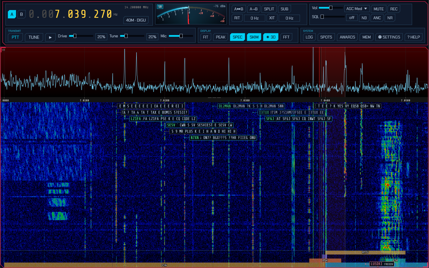
- The SKIM button in the Display module opens the skimmer popup: one row per skimmer (CW, PSK, RTTY), each with an on/off button and its own squelch — the minimum SNR (dB) a decoded signal must reach before it earns a box. The SKIM button stays lit while any skimmer runs, and a skimmer you switch off stops decoding entirely (it costs no CPU) and its boxes disappear. Like the band/mode popup, this one fades away by itself after a few seconds; keep the pointer on it to hold it open.
- On a SoapySDR (IQ) source all three skimmers are on by default, with
squelch at
0 dB— everything that decodes is spotted. Raise a squelch to keep only the stronger signals of that mode on the waterfall. - Each decoded signal appears as a box next to its trace on the waterfall, showing the callsign (once resolved, for CW) and a rolling tail of decoded text. Boxes fade out a few seconds after a signal stops.
- Click a skimmer box to tune to that signal and switch to its mode — CW for a CW spot (which lands it on the CW panel’s cursor, 2.14), PSK or RTTY for a digimode spot (which also opens the messaging panel, 3.3).
Band-aware gating. To avoid noise and false decodes — and to avoid paying
for either — each skimmer only runs where its mode is used: the CW skimmer in CW
sub-bands, and the PSK and RTTY skimmers in each band’s PSK/RTTY calling
sub-bands — with the FT8, FT4, FT2, WSPR, and QRSS watering-holes excluded so
their signals aren’t mistaken for PSK or RTTY
(the WSPR window and the slow-CW/QRSS beacons just below it sit inside the RTTY
sub-band on several bands, so they’re carved out explicitly). A skimmer whose
window holds none of its own sub-bands stands down completely and costs nothing
until you tune back onto one — so an SDR parked on the broadcast FM band, the air
band or any other non-amateur allocation is not running a neural CW decoder over
it. Which frequencies count is the band plan’s to say
(bandplan.json), and it ships with the HF allocations
only. The skimmer-decoded text is a coarse best-effort copy; switch to the mode (click a box) for a clean
decode — the CW skimmer runs the same decoder as the CW panel, but over hundreds
of signals at once and re-reading each one only twice a second, so a signal you
care about is always better copied on the panel.
Note: the skimmers are a wideband feature and work only with true IQ/SDR sources (SoapySDR, HPSDR, TCI). They are unavailable when a CAT radio is feeding demodulated audio (see settings), because that mode has only a narrow audio slice rather than a wide IQ span.
5. ISM band decoder
The licence-exempt ISM bands are full of small unattended transmitters: weather and soil sensors, water and heat meters, doorbells, thermostats, alarm contacts, tyre-pressure sensors, gate remotes. Each one wakes up, sends a few milliseconds, and goes back to sleep for a minute. The ISM button in the System module opens a window that reads them and lists each device it has heard, with its readings in real units.
That button turns green while the decoder is running, not while the window is open — like SAT and SCAN, because it is spending a receiver on your behalf whether or not you are watching. Closing the window therefore leaves it lit. The switch is DECODING inside the window itself.
There are two sets of decoders behind that window. SDRoxide’s own read a handful of protocols on the European 868 MHz channels, in detail and with every checksum verified — those are what the rest of this section describes first. The rtl_433 decoders (§5.4) add several hundred more across 315, 345, 433, 868 and 915 MHz. Most people will want both switched on.
- DECODING / OFF switches the decoder on. It costs four downconverters and a burst detector while it runs, so the ISM button stays lit — like SCAN and SAT — whenever it is decoding, whether or not the window is open.
- sql is how far above the channel’s own noise floor a transmission has to
stand before it is decoded. The default
12 dBis well below where these protocols stop working, so it is not what limits sensitivity: it is what stops the detector opening on noise. Lower it if you suspect you are missing a distant sensor; raise it on a noisy site. - The family buttons — WEATHER, METERS, HOME, LORA — choose what to listen for. Only WEATHER is implemented so far; the others are drawn greyed out rather than hidden, because those devices are on the air whether or not SDRoxide can read them yet.
5.1 Where it listens, and where to tune
The ISM channels are at fixed frequencies, so the decoder parks a receiver on each of them rather than searching the band:
| Channel | What is on it |
|---|---|
| 868.300 MHz | Weather and soil sensors, wireless M-Bus mode S, KNX-RF, EnOcean, Homematic |
| 868.420 MHz | Z-Wave (EU) |
| 868.950 MHz | Wireless M-Bus modes T and C — most modern meters |
| 869.525 MHz | Wireless M-Bus mode N, Homematic long range |
Those four span about 1.4 MHz, and the decoder can only reach the ones inside the
IQ your receiver is actually delivering. The window lists every channel with a
lamp: green for one being listened to, and a reason beside any that is not —
outside the receiver's window if you are tuned elsewhere, not decoded yet if
nothing in this build reads it.
Press 868 MHz EU in the band row to get there — it tunes the radio for you, and on a receiver handing over ~2 MHz the window then reaches the channels that matter. Those buttons are the only tuning control in this window; there is one per band, and they serve both sets of decoders at once.
There is one window and both sets of decoders share it, so on a receiver with room to spare — a PlutoSDR at 3.84 Msps, say — it is made wide enough to hold the channels above and rtl_433’s band at the same time. Where there is not room for both, the window goes where the most decoding gets done, which is why a channel with no decoder behind it never costs you one that has: switching rtl_433’s 868 MHz band on can push 869.525 MHz out of view, and that channel reads nothing either way.
Do not tune the dial to a channel to try to reach it. The window follows the receiver’s own centre frequency, not the dial, and on a zero-IF radio those are not the same place — a PlutoSDR parks its local oscillator 960 kHz above the dial, so putting the dial on 868.950 MHz moves the stream to 869.910 and takes the 868 MHz channels out of reach. The band buttons put both where they belong.
Note: like the skimmers, this is a wideband feature. It needs a true IQ source and is unavailable when a CAT radio is feeding demodulated audio.
On an RX-888, 868 MHz is reached through its VHF tuner, and its wideband downconverter delivers 2.025 Msps at the default panadapter width — enough for the whole channel plan, but only just, which is why the centre frequency matters there. A wider panadapter width (15.20) covers it with room to spare.
5.2 Reading the device list
One row per device, not per transmission: these things repeat themselves for months, and the question is what is around you and what it is reading. Each row shows how long ago the device was last heard, the frequency measured from the signal (not the channel it was found on, so two sensors 40 kHz apart read as two frequencies), the protocol, the device’s own identity, the signal strength, how many frames have been accepted from it, and the readings.
- The ×N count is worth attention. A device heard once is a checksum that happened to pass; one heard fifty times is really there.
- Click a row to tune the receiver to that device, so you can watch it on the waterfall.
- Devices are also labelled directly on the waterfall, in green, at the frequency they were heard on. Those labels do not fade: a sensor that has gone quiet for a minute is still where it was, and the window’s age column is where “how long ago” is answered.
- The bursts / decoded line under the channel list is the honest measure of what is happening. Many bursts and no decodes means the band is busy with devices SDRoxide cannot read yet — which around 868 MHz it usually is.
5.3 What is decoded so far
LaCrosse IT+ — the TX29-IT, TX35, TX35DTH-IT and the Conrad and TFA units that are the same radio in a different case. Temperature, humidity where the sensor has an element for it, and the battery state. Frames are accepted only when the length field, the CRC-8, the BCD temperature digits and the temperature range all agree, so a row in the list is a real reading rather than a lucky checksum.
Fine Offset — the Fine Offset Electronics sensors, which are also sold as Ecowitt, Froggit, Ambient Weather, SwitchDoc and Misol. Every frame in this family carries two independent checks, a CRC-8 and a byte sum, and both must pass — which is what makes it safe to decode on a band this busy.
- WH51 / WN31 soil moisture (and the SwitchDoc SM23): moisture percentage and cell voltage.
- WH24 / WH65 / WS69 / HP1000 outdoor arrays: temperature, humidity, wind direction and rainfall. Wind speed and gust are deliberately left out — the published reference capture contradicts itself on those two fields (it quotes a gust below the average, which no anemometer reports), and rather than publish a number derived from an inconsistency they are omitted until there is a capture to settle it.
- WS80 outdoor array: temperature, humidity, wind average, gust and direction, UV, light and battery voltage — the full set, and this one’s reference capture is internally consistent.
- WS90 “Wittboy”: the same measurements plus the supercapacitor voltage.
- WS85: wind average, gust and direction, battery and supercapacitor.
- WN34 / WN38 soil and water probes (Froggit DP150 / DP35, Ecowitt WN34S, WN34L, WN34D): temperature and cell voltage.
- WH57 lightning detector (Froggit DP60, Ambient Weather WH31L): distance to the last strike, the running strike count, and what the sensor is reporting — a strike, interference, noise, or that it has just powered up.
- Any other Fine Offset sensor whose two checks pass is still listed, with its model or family code and its serial but no readings — a WH45 air-quality unit will appear as “payload not decoded”. That is not a guess: a CRC and an independent sum both agreeing means it really is one of these sensors, and knowing it is there is more use than silence.
Rainfall on the WS85 and WS90 is not decoded, and the row says so rather than reading zero. The layouts set aside five bytes for rain and name two of them as the total, but the only published capture of each was taken in the dry — so nothing there distinguishes a right guess from a wrong one, and on the WS90 a neighbouring byte would read as a plausible 18.6 mm. A rain total read out of the wrong bytes is worse than no rain total. If you have one of these and it rains, a recording made with
--record-iqwould settle it.
Bresser — the Weather Center 5-in-1, 6-in-1 and 7-in-1 outdoor sensors, the water-leakage sensor, and the units rebadged from them (Froggit among others).
- 6-in-1 family: temperature, humidity and battery. Verified on air — the readings matched the actual conditions exactly. Byte 6 says which member sent the frame, so a thermo-hygro unit, a pool thermometer and a soil probe are each named; the soil probe reports moisture on its own sixteen-step scale rather than a humidity percentage.
- 7-in-1 / 3-in-1 / 8-in-1: temperature, humidity, wind average, gust and
direction, rainfall, light and UV. The frame is whitened and every field is
BCD; a sensor without an anemometer or a light cell sends
0xfdigits and those readings are simply absent rather than reported as zero. The air-quality members of the same family (CO₂, HCHO/VOC) are named as present but not read — those are not weather measurements. - 5-in-1: temperature, humidity, wind average, gust and direction. Rainfall is left out: it is two BCD bytes whose digit order no published capture states a value for, and a rain total with its digits reversed is worse than none.
- Water-leakage sensor: wet or dry, the channel, and the battery state. It measures nothing, so it has no readings — only a state.
- A Bresser rain gauge shares the framing with a payload meaning something else; it is listed as present without a reading.
The 7-in-1 is the weakest frame in the band that SDRoxide accepts, and worth knowing as such. A 5-in-1 carries about a hundred bits of redundancy and a leakage sensor a 16-bit CRC plus five checkable flag bits; a 7-in-1 has a 16-bit digest and nothing else, so one random burst in 65 536 passes it before any other check. Everything the format offers on top is taken — the sensor-type nibble must be a documented one, every BCD field must be wholly decimal or wholly
0xf, and a value outside the range its sensor can produce fails the whole frame rather than being dropped on its own — which together gets it to around one in 200 000. This is what the heard count in the device list is for: a device seen once may be a lucky digest, one seen fifty times is really there.
These sensors run at 8.2 kbaud — less than half the Fine Offset rate — behind the same channel, preamble and sync word. That mattered more than it sounds: see the note below.
Z-Wave — the European 868.42 MHz channel at the 9.6 kbit/s rate, which is
Manchester-coded and so needs a decoder that slices at 19 200 chips a second
rather than at the data rate. Each report names the home identifier, the
source and destination nodes and the frame type, because Z-Wave encrypts at
the application layer and not the link layer: the mesh has to be able to route a
frame without opening it, so the routing header is in clear even on a secured
network. The command class is named where it is a familiar one. A frame carrying
a secured command class is marked payload encrypted — SDRoxide holds no keys.
This one was not transcribed from a write-up: the frame layout was derived from a
capture taken off the air with ism_forensics, and confirmed by its own checksum
reproducing.
Homematic BidCoS — 868.3 MHz, recognised and reported as present, not read. The recognition is solid: a 32-bit sync word at the right rate and deviation. The contents are obfuscated by the protocol, and rather than derive a de-obfuscation from prose and apply it to a single unverifiable capture — which would produce device addresses that look authoritative and might be nonsense — the frame is listed with its bytes and no interpretation.
Unidentified bursts — the UNKNOWN button. Off by default. With it on, every
burst that gates but matches no decoder is listed anyway, classified and
described by what could be measured about it:
| Class | Decided by |
|---|---|
2-FSK |
two tones, constant envelope |
OOK |
the envelope is keyed down to the channel’s own noise floor |
chirp |
the frequency sweeps instead of settling on tones |
carrier |
too little frequency spread to be two tones |
None of that needs a symbol rate to have been recovered, which matters because a chirp has none to recover. The row also carries the deviation, the rate, and — where the burst is framed — the two bytes immediately after its preamble. Those two bytes are the sync word for every protocol in this band, so they identify the protocol even when nothing can read it, and they are used as the device identity so repeats collapse into one row with a count. A chirp or a carrier has no preamble to derive one from, so those are listed by rounded frequency instead.
On-off keying is measured differently. The symbol-rate estimator used everywhere else counts how often the frequency crosses the carrier — the right measurement for a constant-envelope signal that moves its frequency, and the wrong one for a signal that does the opposite. Over the silent half of a keyed burst the discriminator is reading noise. So a burst classified
OOKhas its rate taken from the envelope instead, as the shortest keying element or as the interval between rising edges, whichever verifies itself better — the second being what pulse-width coding needs, which is what nearly every cheap remote and sensor on these bands actually uses.
That is how the 868 MHz band around this author’s bench turned out to hold a
2c4c emitter at 10 kbaud that heartbeats every 60 seconds and a d391 one —
0xd391 being the factory default sync word of the TI CC1101, which a great many
cheap 868 MHz devices never change. Neither is decoded. Knowing they are there,
how often they speak and what to search for is most of the way to finding out
what they are.
Wireless M-Bus and LoRa recognition are not implemented yet.
Why a sensor can be plainly visible and still not decode. Each protocol declares a symbol rate, and the bit slicer used to search only ±20 % around it. A Bresser sensor at 8.2 kbaud therefore stayed invisible on the very channel it shares with the 17.24 kbaud Fine Offset family — its sync word sitting in the trace with nothing ever slicing at a rate that could see it. The slicer now also tries the rate measured from the burst itself, which is what a sync word and a CRC are for. If you are writing a new protocol module, this is why the
symcolumn inism_replay --surveymatters more than the nominal rate in any datasheet.
On encrypted meters: when wireless M-Bus support arrives, most modern German and Austrian meters will still only report their manufacturer, serial and device type — their readings are AES-encrypted and SDRoxide holds no keys. That is a useful meter inventory, but it is not a meter reading.
5.4 The rtl_433 decoders
Under RTL_433 DECODERS is a second set of decoders, from the rtl_433 project, built into SDRoxide. It adds several hundred device protocols and, unlike the decoders above, reads OOK as well as FSK — which is most of what is on the air below 868 MHz.
There is no switch: if your build has them, they decode whenever the ISM decoder is running. All you choose is which band to listen on.
Bands
The band buttons pick where to listen. Pressing one selects that band and tunes the radio to it, because the decoder listens inside whatever IQ the receiver is delivering. Only one band runs at a time: they are hundreds of megahertz apart and no receiver covers two at once.
| Band | Where it is used | What is on it |
|---|---|---|
| 433.92 MHz | Europe, and worldwide for remotes | Weather stations, thermometers, soil and pool sensors, doorbells, garage and gate remotes, alarm contacts, PIR sensors, tyre-pressure sensors, energy monitors, remote switches |
| 868 MHz EU | Europe | The same weather families as the decoders above, plus Fine Offset and Bresser variants they do not cover, and assorted home-automation devices |
| 915 MHz US | North America, Australia | Acurite, LaCrosse and Oregon Scientific weather stations, tyre-pressure sensors, utility meters (ERT/SCM), Honeywell alarm sensors |
| 315 MHz US | North America | Tyre-pressure sensors, garage and gate remotes, alarm contacts |
| 345 MHz US | North America | Honeywell/Ademco, 2GIG and Vivint alarm sensors — door and window contacts, glass-break detectors, motion sensors |
433.92 MHz is the one worth trying first if you have never looked: it is busy almost everywhere, and none of SDRoxide’s own decoders reach it.
Bandwidth
bw is how wide a window rtl_433 gets around the band centre.
AUTO gives each band the width it normally needs: a quarter of a megahertz on 315, 345 and 433 MHz, where everything is slow OOK crowded around one frequency, and a full megahertz on 868 and 915 MHz, where the FSK devices are faster and spread over several channels. That is what rtl_433 itself uses, and it is the right answer nearly always.
Choose a width by hand for the two cases it is not:
- Your receiver cannot deliver the band’s own width. A window is usable only
across the middle three quarters of what the front end hands over, so 868 MHz
at AUTO needs about 1.4 MHz of IQ. On a receiver giving less, the band row
reads
too wide for the receiver's windowand nothing decodes — pick 250k or 500k and it will. - The device you want is further off centre than AUTO reaches. Widening to 1024k or 2048k covers more of the band at once, at the cost of more work per second and a slightly higher noise floor per device.
Narrowing has the opposite catch: 250k on 868 MHz watches 868.525 to 868.775
MHz and so hears neither of the two busy European sub-bands. The band row and
the frequency beside rtl_433 say what is actually being watched.
The figure shown there is not always the one you picked. The window is a whole-number division of the receiver’s stream, so a request for 250 kHz out of 1.4 Msps settles on 350, and 1024 kHz out of the RX-888’s 2.025 Msps takes the whole 2025 because half of it would be too little. It is never narrower than what you asked for — a lane given less than the band it was chosen for would be deaf at the band’s edges, and rtl_433’s own wireless M-Bus decoder wants at least 1.2 Msps whatever the band asks for.
What it adds
Broadly: weather (Acurite, Ambient Weather, Bresser, Ecowitt, Fine Offset, LaCrosse, Oregon Scientific, Nexus, Rubicson, TFA and many rebadges), tyre-pressure sensors from most car makers, utility and sub-metering (ERT/SCM gas, water and electricity meters, Efergy and Owl energy monitors), security and access (door and window contacts, PIR sensors, smoke alarms, gate and garage remotes, key fobs), environment (soil moisture, pool and fridge thermometers, air quality, lightning detectors) and a long tail of remotes, doorbells and thermostats.
Devices appear in the same list as everything else, with rtl_433 in the
protocol column and the device’s model name beside it.
Where it takes over
Where both sets of decoders can read a device, rtl_433 reads it, because it
knows far more variants — fifteen LaCrosse decoders to SDRoxide’s one, nineteen
Fine Offset to seven, eight Bresser to four. The channel list says
handled by rtl_433 for those, and the panel lists them under handled by
rtl_433. This is why a sensor you know as Bresser may appear as rtl_433
with a model of Bresser-6in1 — same device, better decoder. Select a band
somewhere else and SDRoxide’s own decoders take 868 MHz back.
Z-Wave and Homematic are never handed over — rtl_433 has no decoder for either, so those two stay with SDRoxide’s own regardless of what band is selected.
5.5 Adding your own decoders (flex specs)
If you have a device nothing decodes, you can describe it yourself — no code, no rebuild. A flex spec is a few lines of text saying how a device modulates and frames its data, and SDRoxide turns it into a working decoder.
They live in one file:
| Platform | Location |
|---|---|
| Linux | ~/.config/sdroxide-brown/rtl433_flex.conf |
| macOS | ~/Library/Application Support/org.sdroxide.sdroxide-brown/rtl433_flex.conf |
| Windows | %APPDATA%\sdroxide\sdroxide\config-brown\rtl433_flex.conf |
The file is created for you, with a worked example commented out, the first time the ISM decoder runs. SDRoxide never rewrites it, so what you put there stays exactly as you wrote it — including your comments and spacing.
The syntax
It is rtl_433’s own flex syntax, unchanged. That is the point: a spec published
on a forum, in a blog post, or in rtl_433’s own
conf/ directory can be
pasted in as-is. Both shapes work — a decoder { ... } block:
decoder {
    name=doorbell,
    modulation=OOK_PWM,
    short=400,
    long=800,
    gap=1000,
    reset=7000,
    match={24}0xa9878c,
    get=@0:{24}:id,
    unique
}
or the single-line form, which is what rtl_433’s -X option takes:
decoder n=doorbell,m=OOK_PWM,s=400,l=800,g=1000,r=7000,match={24}0xa9878c
Put as many as you like in the file, one block each. # starts a comment.
The keys you will use most:
| Key | Means |
|---|---|
name / n |
What the device is called in the list. Required. |
modulation / m |
How it keys the carrier. Required — OOK_PWM, OOK_PPM, OOK_PCM, OOK_MC_ZEROBIT, FSK_PCM, FSK_PWM and a few more. |
short / s, long / l |
The two pulse widths, in microseconds. Required (except for the Manchester modulations, which have one). |
gap / g |
Longest gap still inside one message, in microseconds. |
reset / r |
Quiet time that ends a message, in microseconds. Required. |
bits, rows, repeats |
How much data to insist on before believing it. Also bits>, bits< and so on for a range. |
match, preamble |
A fixed bit pattern the message must contain or start with, as {count}hex — the main defence against decoding noise. |
get |
Pull a named field out of the bits: get=@0:{8}:temperature_C. Repeat for each field. |
unique |
Report one line per message rather than one per repeat. Worth adding. |
short, long, gap and reset are timings you measure from the device
itself — the ism_replay --survey tool in
§5.7 prints them from a recording.
Name your get= fields well. Call one temperature_C, humidity,
pressure_hPa, power_W, battery_ok, wind_avg_km_h and so on, and it shows
up as a proper reading with units, converted to the same units as every other row
in the list. Any other name still appears, just as plain text.
Loading changes
Press RELOAD DECODERS in the ISM window after editing the file. The devices already in the list stay there, and the notice bar says how many decoders loaded and how many were refused.
Deleting the file and reloading gets you a fresh one with the commented example back.
When a spec is wrong
Every spec is checked before it is used. One that does not pass is listed in the ISM window with its line number and the reason, and skipped — the others still load, so one typo costs you one decoder rather than all of them.
The check is deliberately stricter than rtl_433’s own command line. rtl_433 reports a bad spec by printing a message and stopping the program, which is fine for a command-line tool and not fine for a receiver you are operating; so anything SDRoxide cannot confirm is safe gets refused with an explanation instead. If a spec is rejected that you believe is valid, the message says which part was not understood.
5.6 Nothing is being decoded
Work down this list; each step distinguishes two causes that look identical from the outside.
- Is anything live? The channel list needs at least one green lamp — the
rtl_433 row counts. All grey with “outside the receiver’s window” means the
dial is wrong: press the band button for the band you want, which tunes there.
A band reading
too wide for the receiver's windowis the other one: the width under bw is more than this receiver can give, so set it back to AUTO or narrower (§5.4). A native channel readinghandled by rtl_433is not a fault; it means the other set of decoders has that one (§5.4). - Is the gate opening? The bursts / decoded line says.
0 burstsmeans nothing is reaching the threshold: lower sql towards 6 dB. A healthy count with0 decodedmeans the band is busy with devices this build cannot read — go to step 4. -
Are your sensors even on these channels? This is the common answer and the one the panel cannot give you. The 868 MHz band is wide, and a great deal of what fills it — the RFID readers at 865.6–867.6 MHz especially — is nowhere near the four channels the sensor protocols use. Record and survey:
sdroxide --record-iq band.iq # 8 bytes a sample: 16 MB/s at 2 Msps cargo run --release -p sdroxide-ism --example ism_replay -- band.iq 868880000 2025000 --survey--surveyignores the channel plan and tiles the whole window, finishing with a histogram of where the bursts actually were. If the traffic is all at 866.5 MHz, no amount of tuning the sensor channels will help — and now you know. - What are they? For each undecoded burst the survey prints the measured
deviation, symbol rate and envelope swing. Candidate frames (
cand) above zero means the right modulation and a frame format this build does not know;cand 0means a modulation this chain does not handle at all, which is what LoRa’s chirps look like. Those columns are what a new protocol module gets written from.
5.7 Checking it without waiting for a sensor
Two tools ship with the decoder. The first writes a synthetic 868 MHz band with four sensors whose readings are known, as an IQ file the radio can tune:
cargo run --release -p sdroxide-ism --example ism_iq -- band.iq 10
cargo run --release -- --file band.iq --rate 2025000 --freq 868880000 --mode NFM
Switch the ISM window on and the four sensors should appear with the readings the generator printed.
The second replays a real capture and reports every burst it finds, decoded
or not — which is how you find out what your own neighbourhood is transmitting.
Capture one with --record-iq (see 5.6), then:
cargo run --release -p sdroxide-ism --example ism_replay -- band.iq 868880000 2025000
cargo run --release -p sdroxide-ism --example ism_replay -- band.iq 868880000 2025000 --survey
The first listens on the channel plan, as the radio does. The second tiles the whole window instead and reports traffic anywhere in it.
The cand column is the useful one on an undecoded burst. Candidate frames mean
the right modulation and a frame format this build does not know; no candidates
at all means a modulation this chain does not handle, which is what LoRa’s chirps
look like.
6. Settings
Everything that configures sdroxide lives in one window, opened with the ⚙ SETTINGS button in the System module (the ⚙ SETUP button in the SPOTS window opens the same dialog on its Spots tab).
The pages run down the left, in four groups, and the page you pick is on the right. On a window too narrow for a column — a phone, or a settings box dragged right down — they run across the top as a tab strip instead, which wraps rather than cutting labels off.
| Group | Pages |
|---|---|
| Station | General · Radio · Audio · CW (the key and the keyer) · UI |
| Radio work | Spots · FreeDV · T/R switch · Profiles |
| Sending | Uploads · Winlink · Servers |
| Setup | Alerts · Controls · TLE |
| Page | What it holds |
|---|---|
| General | Which version this is, your callsign, grid, IARU region and channel plan (11M/CB), and who may connect remotely. 6.1 |
| Radio | Which rig sdroxide talks to, and how. 6.2 |
| Audio | Your speakers and microphone, this radio’s sound card, and where recordings are written. 6.13 |
| Radio | Which rig sdroxide talks to, and how. 6.2 |
| UI | Frame rate, waterfall palette, spectrum background, spot label colours, 3D cloud rendering, and the spoken announcements. 6.3 |
| Alerts | Sounds that ring when a decode matters: a station calling you, a new DXCC entity or grid. Audible alerts |
| Controls | Keyboard, mouse and MIDI bindings. 6.4 |
| Spots | DX cluster, POTA, SOTA and PSK Reporter feeds, and the broadcast station list. 6.5 |
| FreeDV | FreeDV Reporter (qso.freedv.org). 6.6 |
| Uploads | Callsign lookup, QSL upload, confirmation download. 6.7 |
| Winlink | The radio-email account, and whether it forwards over the internet or on the air. 6.8 |
| Servers | Hamlib rigctld, the built-in TCI server, and the WSJT-X UDP broadcast. 6.9 |
| T/R switch | The relay that grounds the SDR’s antenna while the station transmits, and the sequencer around it. 6.11 |
| TLE | Satellites to track beyond the amateur set, and their frequencies. 6.10 |
| Profiles | Named snapshots of how the station is set up, put back on in one click. 6.12 |
Most settings take effect the moment you change them. The ones that open or rebind a connection — the radio itself, the spot feeds, FreeDV Reporter, and the two servers — have their own APPLY or Apply / reconnect button, noted in each section below, and so does Winlink, whose account is read by the next forwarding session rather than the moment you type it. Nothing here needs a restart.
Settings are written to the per-user config directory (§13):
display preferences to config.toml, the radio to radio.json, key/mouse/MIDI
bindings to input.json, feeds and credentials to net.json, the two servers
to rigctld.json, tciserver.json and wsjtx.json, the satellite
additions to satellites.json, the transmit/receive switch to relay.json,
and the saved setups to profiles.json.
Most of those files describe the station, not the screen: the feeds it
connects to, the servers it offers, the satellites it tracks, the radio it has.
They live on the machine the radio engine runs on, and the engine tells every
client what they say — so the Radio, Spots, FreeDV, Uploads,
Winlink, Servers, TLE and Profiles tabs show, and change, the real thing
whether you are at the shack machine, on a native remote client or in a browser tab. The T/R switch
tab is the same kind of thing — the relay is bolted to the antenna, not to your
desk — with one difference worth knowing before you use it from away: its
TEST buttons operate real hardware in a room you are not in. (The Radio tab
keeps back the parts that are about a machine rather than about the radio:
which interface to open, and the buttons that scan a bus or test an address. See
8.4.) input.json and the [ui], [speech] and [alerts]
tables of config.toml are the exception, and belong to the screen in front of you: a
display preference and a knob on your desk have nothing to do with the radio in
the other room — and so does the [remote_server] address on the General
tab, which is where this screen goes rather than anything about the station it
arrives at. The rest of config.toml — including the [remote_access]
sign-in — belongs to the engine’s machine, which is why the Remote access
section of the General tab is only shown there.
6.1 General: station, audio and remote access
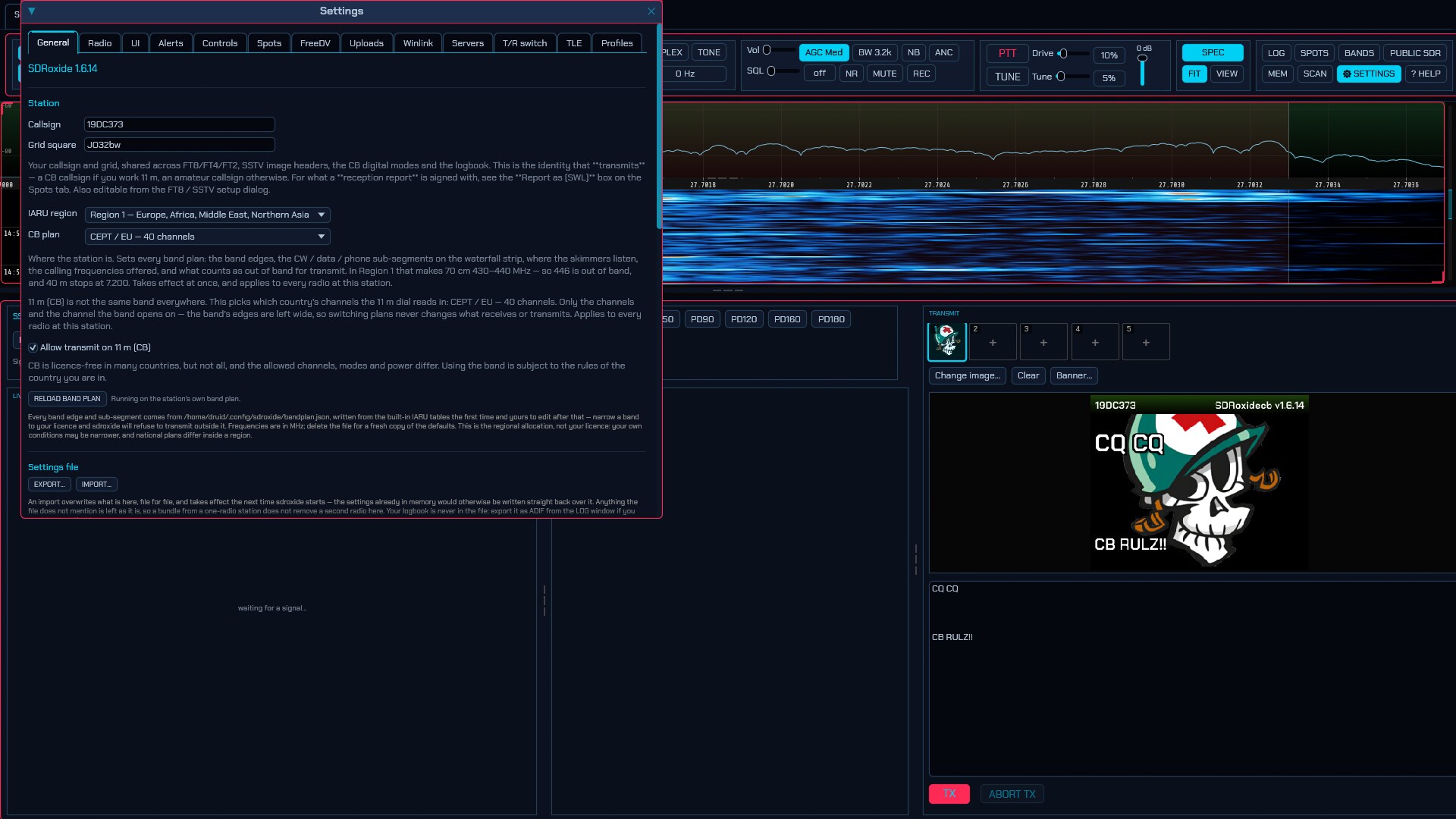
At the top is SDR Oxide Brown and the version number this copy was built
from — the one to quote in a bug report, so there is no need to go looking for
the binary to ask it. Brown names which build this is: this fork’s variant,
told apart at a glance from the upstream program, since the two install happily
side by side and read the same settings. It is a variant name, the way SDR++
Brown names that program’s second build — it says “this build, not upstream”
without saying what is in it. It is also the window and taskbar title, which carries the version beside it,
and --version on the command line prints it (with the _brown release suffix, e.g.
SDR Oxide Brown 1.9.2_brown).
The release tags carry the same suffix: v1.9.2_brown rather than upstream’s
v1.9.2. The version the program reports to other software — the SSTV id, the
WSPR/PSK Reporter fields, the ADIF program id — is left as plain 1.9.2, because
the suffix is for a person and a tag, not for anything a machine parses.
Station — your Callsign and Grid square. This is the identity the whole program uses: FT8/FT4/FT2 exchanges, the SSTV image header, the logbook, the DX cluster login, and FreeDV Reporter. The same pair is editable from the FT8 / SSTV setup dialog; there is only one copy of it.
IARU region — which of the three ITU regions your station is in:
| Where | |
|---|---|
| Region 1 | Europe, Africa, the Middle East, northern Asia |
| Region 2 | The Americas |
| Region 3 | Southern and eastern Asia, Australasia, the Pacific |
The amateur allocations are not the same in all three, so this one setting decides every band plan sdroxide draws and enforces:
- Band edges — 70 cm is 430–440 MHz in Region 1, 420–450 in Region 2 and
430–450 in Region 3, so 446 MHz is out of band in Europe and in band in the
Americas. 40 m runs to 7.200 outside Region 2 and to 7.300 inside it; 80 m
ends at 3.800, 4.000 or 3.900; 160 m starts at 1.810 in Region 1 and 1.800
elsewhere; 6 m and 2 m are 2 MHz wider outside Region 1. 9 cm is
3400–3475 in Region 1 and 3300–3500 in the other two; 6 cm starts at 5650
everywhere and stops at 5850 in Region 1 against 5925 elsewhere. Three bands a
region can simply not have, so where they are absent they get no band button
and band stepping passes them by: 4 m (70.000–70.500) is Region 1’s alone,
and 1.25 m (220–225) and 33 cm (902–928) are Region 2’s. These
edges are what the band buttons jump to, what
Banda frequency reports as, and — withtx_ham_onlyset, which is the default — where transmit is refused. -
11 m (
M11) is on the bar and is not an amateur band. 26.965–27.860 covers the forty citizens’-band channels (the same grid under CEPT, the FCC and the ACMA) and reaches up into the UK’s second 27.6 MHz block — widened so the 27.700 SSTV channel sits inside the band — and it is here because it is a band people work, busy in Europe and with its own digimode conventions on the ordinary channel grid: FT8 on 27.265 (ch 26), JS8 on 27.245 (ch 25), SSTV on 27.255 and 27.375 (ch 23 and 37), SSTV’s wider calling channel on 27.700, 1200-baud packet on 27.235 and 27.365 (ch 24 and 36). Those appear in the ⇵ frequency picker like any other convention, and pressing 11M in a digital mode lands on the mode’s channel. The exchange itself follows WSJT-CB — grid-less, one call at a time, with country flags on every decode; see §3.2.9. What does not follow is permission to transmit: withtx_ham_onlyset (the default) sdroxide refuses to key up there, because an amateur licence does not grant the citizens’ band and this end cannot check what else you hold — the refusal names the band and says how to lift it. A contact there logs with an empty ADIF band, because ADIF’s enumeration runs 12 m, 10 m, 8 m with nothing in between (issue #396).The frequencies above the forty-channel grid that circulate on the same lists — 27.500, 27.585, 27.635, 27.710 — are the freeband, which no administration grants, and sdroxide does not offer them as channels (the 27.700 SSTV calling channel aside). They tune by hand like anything else — the widened band edges reach them — and a licence that does cover part of that range (the UK’s second CB block starts at 27.60125) goes in
bandplan.jsonand in your own saved frequencies.11M/CB — which channel plan the dial reads in, set on the General tab beside the IARU region and in the band/mode menu. Two licence-free services are carried: the 11 m citizens’ band and PMR446 at 446 MHz. The world shares the 40-channel CEPT/FCC table (EU); Germany adds a high band for 80 (DE); the UK’s 27/81 channels sit at their own frequencies (UK); the US and Australia work the shared 40 in AM and SSB; WORLD (the default) is the 40 plus the high band, permissive about mode. PMR is the 16 narrow-FM PMR446 channels of 446.0–446.2 MHz, dPMR the 32 dPMR446 FDMA channels of the same band. The plan picks the channels, the channel the band opens on, and the
CH nntag on the tuning line — it does not move the band’s edges, so switching plans never changes what receives or transmits. It is a station setting (cb_planinconfig.toml), so every radio and every client at the station agrees.The channel tag follows the dial, not the band. Tune to any frequency on one of the selected plan’s channels — 27.245 on 11 m, 446.09375 in the PMR plan — and the tuning line names it. PMR446 is a licence-free service beside 11 m, not an amateur band, so it has no button of its own on the band bar: reach it by tuning (or a memory), and it carries no transmit permission here, exactly as 11 m does not.
Allow transmit on 11 m (CB) — sits under the CB plan, and is off by default only because the amateur-band lockout is generic and refuses every band that is not an amateur allocation; 11 m is a separate service. It is the deliberate way to open CB — a band made for two-way use — without dropping the lockout for the broadcast bands too. Switching it on shows a one-time note (CB is its own service, and its channels, modes, power and equipment are your country’s rules) and the permission stands once that is confirmed, remembered per screen. It opens 11 m and nothing else. A station setting (
cb_tx_allowedinconfig.toml), so it travels to every client along with the CB plan. - Longwave, medium wave, shortwave and FM broadcast —
LW,MW,SWandFMare on the bar for the listener the way 11 m is for the CB operator. None is an amateur allocation, so withtx_ham_onlyset (the default) the transmit lockout holds there exactly as it does on 11 m; and none has an ADIF band, so a broadcast contact logs with an empty band like a CB one. The spans are longwave 148.5–283.5 kHz, medium wave 526.5–1606.5 kHz (the Americas’ expanded band runs to 1700, and those regions’ edges follow), the whole shortwave broadcast span 2.3–26.1 MHz, and VHF FM broadcast 87.5–108 MHz. The dial buttons land on 198 kHz AM, 1 MHz AM, 6.175 MHz AM (the 49 m band) and 100 MHz WFM, and band stepping walks through them like any other band. Shortwave deliberately overlaps the amateur HF bands — the broadcast allocations thread between them and in places sit inside them, and no one span can hold them without touching what is already on the bar. The amateur band always wins the name: a frequency that is in both reports as the amateur band, andSWowns only the broadcast-only ground between them — 6.175 MHz isSW, 14.200 MHz is 20 m. The waterfall labels that make these bands worth listening to are in §10.6. - What a band is called — the 5650 MHz band is 6 cm to the IARU
Region 1 VHF handbook, the RSGB, the WIA and the NRRL, and 5 cm to plans
across the other two regions, so the band button, the band-plan strip and the
voice announcements all say whichever your own region says. The log does not
follow it: ADIF defines
6cmfor 5.65–5.925 GHz and nothing called5cm, so that is the band a contact there is filed under wherever you are. - Sub-segments — the CW / data / SSB / beacon blocks on the waterfall’s band strip (§ 2.8). Region 1 splits the top of each band into a phone sub-band; Regions 2 and 3 hand it to all modes, and their 40 m data segment starts 5 kHz lower.
- Skimmer windows — where the PSK and RTTY skimmers listen. 40 m PSK is around 7.040 in Region 1 and 7.070 in the other two; RTTY, 7.040 against 7.080.
- Calling frequencies — the ⇵ frequency button and the digital band buttons offer your region’s convention: PSK31 and RTTY on 40 m, and SSTV on 80 m and 40 m (3.730 / 7.165 in Region 1, 3.845 / 7.171 elsewhere — and 3.845 is outside the Region 1 allocation altogether, so it is never offered there). FT8’s 4 m dial, 70.174, goes the same way: it is offered in Region 1 and in neither of the others, which have no 70 MHz band to put it in. On 13 cm both 2320.174 and 2304.174 are offered everywhere — the narrow-band segment of that band is at 2320 under the Region 1 plan and at 2304 in the Americas, and stations work both — but the band button lands on the one your own region’s plan puts narrow-band modes on, and the other is annotated in the picker.
The default is Region 1, which is the band plan every sdroxide before this
setting had; an existing installation is not moved by upgrading. It is a
property of the station, stored as region in config.toml on the machine
the radio is attached to and announced to every client, so a remote operator
sees the band plan of the radio they are driving rather than of wherever they
happen to be sitting. It takes effect immediately — no APPLY, no restart.
The band plan file
The numbers behind all of that live in bandplan.json in the config
directory (§13), and they are yours to change. On
first start sdroxide writes the built-in IARU tables there; from then on that
file is the authority for every band edge, sub-segment and skimmer window in the
program.
The General tab shows the path and a RELOAD BAND PLAN button, which re-reads the file on the machine the radio is attached to and applies it without a restart — so the loop is: edit, save, click, done.
The file is one row per line, in megahertz, and it explains itself in a
readme field at the top (JSON has no comments). Each region has four lists:
| List | What it sets |
|---|---|
bands |
The allocations. band is one of Lw Mw M160 M80 M60 M40 M30 M20 M17 M15 M12 M10 M11 M6 M4 Fm M2 M125 M70 Cm33 Cm23 Cm13 Cm9 Cm6 Cm3 — metres up to 2 m, then the band’s own name, Cm from 33 cm up because M6 was already 6 m, and Lw, Mw, Sw, Fm for the broadcast services (see the bullet above for what Sw deliberately overlapping the amateur bands does). Leave a band out and the region does not have it — with one exception, below. |
segments |
The CW / data / phone / beacon / all-modes blocks on the waterfall strip. kind is Cw, Digi, Phone, Beacon or All. |
psk_windows |
Where the PSK31 skimmer listens. |
rtty_windows |
Where the RTTY skimmer listens. |
"region1": {
  "bands": [
    {"band": "M2", "lo_mhz": 144.0, "hi_mhz": 144.4},
    ...
That edit is the common one: narrow a band to your own licence, and with
tx_ham_only set (the default) sdroxide refuses to transmit outside it. The
band buttons, the waterfall strip and the frequency displays all follow.
On a slotted digital mode the lockout vets what actually radiates, not the
dial. FT8, FT4, FT2, JS8 and WSPR transmit at the dial plus an audio offset,
so the check is dial + offset + the mode’s occupied bandwidth, and it is made
against the sub-segments rather than the band edges — bandplan.json holds
one range per band, and a licence like the UK’s 60 m needs eleven. Narrow the
segments there and the lockout narrows with them; nothing about this is
UK-specific. An emission may cross from one sub-segment into a touching one — a
signal reaching out of the digital segment into the phone one is poor manners,
not out of band — but it may not cross a gap. Where the table says nothing
about your dial, no opinion is offered, so a band plan with a hole in it never
becomes a lockout for someone legitimately in it. Auto TX FRQ obeys the same
limit when it hunts for a slot, so it stops choosing frequencies the lockout
would then refuse.
A band sdroxide adds later — 4 m (M4) was the first, and 1.25 m (M125),
33 cm (Cm33), 23 cm (Cm23), 13 cm (Cm13), 9 cm (Cm9), 6 cm (Cm6),
3 cm (Cm3), 11 m (M11) and the broadcast services
Lw, Mw, Sw, Fm since — is not in a file
written before it existed, and a file that has never heard of a band is not
saying you have not got it. So a band on that short list is filled in from the
built-in tables when your file names it in no region at all, exactly as a
fresh file would have it. Give it a row anywhere and your file decides it
everywhere again, in all three regions, like every other band.
If a row says something impossible — edges the wrong way round, a band listed
twice, GEN where a real band belongs — that row is dropped, the rest of the
file is used, and the notice bar says which one and why. If the file will not
parse as JSON at all, sdroxide runs on the built-in tables for that session and
tells you so; your file is left exactly as it is, unlike the files sdroxide
writes for itself, because a half-finished edit should survive the start that
could not read it. Delete the file to get a fresh copy of the defaults — one is
written on the next reload or start.
This is the regional allocation, which is the widest set of edges the region’s amateurs share. Your own licence may grant less (and occasionally more), and national band plans differ inside a region. Nothing here is a substitute for your licence conditions — which is exactly why the file is editable.
SWR guard — Stop transmitting on high SWR, and the ratio it trips at.
Armed by default at 2.5:1. When the radio reports an SWR at or above the
figure, sdroxide stops the transmission and keeps transmit locked out until
you acknowledge it — the point being that a fault which clears itself when you
release PTT teaches you nothing and lets you carry on transmitting into it. See
§ 2.10 Transmit for what it does on the air and how to clear a
trip; in config.toml the pair are swr_guard and swr_limit.
It needs a rig that measures SWR and reports it over CAT or TCI — the Icom CI-V
dialect, the Yaesu/Kenwood/Elecraft/ELAD/QRP Labs dialects, rigctld, flrig, and
TCI. On anything
that never sends a figure (any IQ radio: HackRF, Pluto, RTL-SDR, an HPSDR
board) the setting is simply inert, which is why it costs nothing to leave on.
Your audio, the radio’s sound card and recordings now have a page of their own — § 6.3 Audio — because they used to sit here under one heading and then, for the radio’s own half, on the Radio tab as well.
Remote access — the Username and Password a remote client has to
give before this station will let it operate: the browser page, another sdroxide
started with --connect, and the 3D view’s tab. See
§ 7.3 Sign-in.
- Both boxes empty leaves the server open — anyone who can reach the port can operate the radio, transmit included. The tab says so in yellow.
- A password with an empty username is a complete setting; clients are then asked only for the password. Most single-operator stations want this.
- Typing here writes
config.tomlstraight away, and the server re-reads it for every sign-in — so a password change holds without restarting the server or dropping whoever is already connected. There is no APPLY. - The section only appears when the engine is running in this process. These
credentials are a file on the machine the radio is attached to, so a remote
client is not shown them: a box there would edit its own machine’s file and
look as though the station’s password had changed when it had not. Set them at
the shack machine, or edit
[remote_access]inconfig.tomlby hand.
Like every other password sdroxide stores — the cluster login, QRZ, eQSL — it is
kept in the clear, so config.toml is worth the same file permissions as the
rest of your config directory.
Signed-in station — which station this client is signed in to, and the way back out of it. Drawn whenever this screen is attached to a station rather than holding one, which in practice means the browser: a sign-in remembered for a day outlives a reload, so there is nothing to think about until you want to. SIGN OUT forgets this device’s sign-in — the cookie has to be taken back by the station, because the page cannot read it — and the connection you are on stays up until you close it. Where a station was too old to hand out a cookie, the line underneath says so and names it, rather than the browser quietly holding a password. See § 8.3 Sign-in.
Connect to a server — the same thing --connect does without the command
line. The machine this screen runs on can drive an sdroxide somewhere else —
the shack, a remote site — as a radio tab of its own. Enter the server’s
Address and Port and press CONNECT; a pasted ws:// or wss://
URL is used exactly as typed and leaves those two boxes greyed out. See
§ 8.2 Connect a native remote client.
6.2 Radio: choosing and configuring the rig
In the native application the very top of the tab carries the radio roster — one button per radio, with the same TX / warning / mute markers as the main window’s tab strip, the ON/OFF switch that opens or closes each radio’s interface without disturbing anything on this page, an × on every radio but the first, and + to add one (§2.17). Everything below the roster configures the highlighted radio; click another button and the whole application switches to that radio, this dialog included. The Name box under the buttons renames the highlighted radio’s tab — left empty, the tab names itself after the interface selected below.
Radio interface, under the roster, selects how sdroxide talks to your radio. Everything below the selector changes to match the choice:
- SoapySDR — a SoapySDR device (wideband IQ). The default, and listed only when SoapySDR support is compiled in. See 6.2.1.
- HPSDR (network) — an OpenHPSDR (Hermes/Metis) Ethernet SDR on the LAN. See 6.2.3.
- CAT / Audio — a CAT-controlled radio with audio over a USB sound card. See 6.2.2.
- TCI (network) — a TCI server such as ExpertSDR3 or Thetis. See 6.2.4.
- SmartSDR / FlexRadio (network) — a FLEX-6000 or FLEX-8000 on the LAN. See 6.2.6.
- Icom LAN (network) — an Icom on its own Ethernet or WiFi port: IC-7300MK2, IC-705, IC-7610, IC-7760, IC-7851, IC-9700, IC-905, IC-R8600. Control, audio and the radio’s spectrum scope over one network connection, with no serial cable and no sound card. See 6.2.10.
- RTL-SDR (USB) — an RTL2832U dongle, driven by sdroxide’s own USB driver with no SoapySDR involved. See 6.2.5.
- RTL-SDR over rtl_tcp (network) — the same dongle plugged into another
machine — a Raspberry Pi at the antenna, say — and published with
rtl_tcp. See 6.2.11. - SpyServer (network) — a receiver published with Airspy’s
spyserveror one of the servers that speak the same protocol: an Airspy, an Airspy HF+ or an RTL-SDR behind it. Wideband I/Q, receive only. See 6.2.14. - SpyServer VFO+FFT, low bandwidth (network) — the same servers in the mode that fits down a WiFi or cellular link: a narrow I/Q stream that follows the dial, plus the server’s own FFT of the whole band for the full-band strip. See 6.2.14.
- KiwiSDR / Web-888 (network) — one of the ~870 receivers published on
rx.kiwisdr.com, or a private one on the same firmware. A ~12 kHz I/Q window that follows the dial, plus the receiver’s own 0–30 MHz waterfall for the full-band strip. Receive only. Browse the public ones with PUBLIC SDR and open one as a radio: see 15.21. - RX-888 (USB) — an RX-888 Mk1 / Mk2 direct-sampling receiver, likewise driven directly over USB, with its firmware bundled and uploaded for it. On a Mk2 the built-in R828D tuner is driven too, so the receiver covers VHF and UHF as well as HF and switches between its two antenna ports on its own. Both the ADC clock and how much of the digitised band the panadapter shows at once are selectable — up to all of it. See 15.20.
- Airspy HF+ (USB) — an Airspy HF+ Dual, Discovery or Ranger, driven by sdroxide’s own USB driver with no SoapySDR and no libairspyhf involved. See 6.2.9.
- Airspy R2 / Mini (USB) — an Airspy R2 or Mini, driven by sdroxide’s own USB driver. A different receiver from the Airspy HF+ above, with its own interface. See 6.2.13.
- HydraSDR RFOne (USB) — a HydraSDR RFOne, driven by sdroxide’s own USB driver with no SoapySDR and no libhydrasdr involved. A fork of the Airspy R2 above rather than a relative of it, and its own interface for that reason: the two cannot drive each other’s hardware. Three RF sockets and seven sample rates. See 6.2.18.
- HackRF One / Pro (USB) — a HackRF One, HackRF Pro, Jawbreaker or rad1o, driven by sdroxide’s own USB driver with no SoapySDR and no libhackrf involved. The one USB interface here that transmits, and half duplex. See 6.2.12.
- SDRplay RSP (USB) — any RSP, through the vendor’s API service. See 6.2.8.
- PlutoSDR (network) — an ADALM-Pluto, driven by sdroxide’s own IIOD client with no SoapySDR and no libiio involved. See 6.2.7.
- ELAD FDM-DUO / FDM-S (USB) — an ELAD FDM-DUO, FDM-DUOr, FDM-S2 or FDM-S1, driven by sdroxide’s own USB driver. On an FDM-DUO this one interface covers the whole radio: the wideband receiver, the CAT control link and the transmit sound card. See 6.2.16.
- LimeSDR + LimeRFE (LimeSuite) — the LimeSDR family through LimeSuite, full duplex both ways, and the LimeRFE front end that no other path can reach: its band filters, LNA, amplifier and transmit/receive relay follow the dial. On a two-chain board the second receiver can carry a second aerial, nulling a local noise source or filling in fades. See 6.2.17.
- RigExpert Fobos SDR (USB) — a Fobos SDR, through RigExpert’s own libfobos. Three inputs that behave as different radios: an RF port through the tuner, and two HF ports that direct-sample with no local oscillator at all and are tuned entirely in software. Both HF ports at once are combined by the same adaptive filter the RSPduo and LimeSDR use. See 6.2.20.
- USB audio radio (sound card) — a radio with no control port: a handheld, a walkie, a USB dongle rig. Its audio comes in on one sound card, transmit audio goes out on another, and the radio keys itself on VOX. See 6.2.21.
There is no auto-detect: you pick the interface, and an interface that cannot be opened falls back to a silent source rather than guessing at another one.
After changing the radio interface, serial port, sound format, or radio-audio device, press Apply / reconnect at the bottom of the Radio tab (or under the CAT radio-audio settings on the General tab). sdroxide rebuilds the radio live — no restart. If the new interface can’t be opened, the previous one keeps running and an error is shown; your tuning resets to the new radio’s default frequency, as it would on a fresh start.
Apply / reconnect is for changing the radio, not for attaching it. If the radio you already configured isn’t there when sdroxide starts — a network rig still booting, ExpertSDR3 launched a moment later, a USB cable plugged in afterwards — sdroxide keeps trying it in the background and attaches by itself, retrying at first every second and then more slowly. The same happens if the link drops mid-session: it reconnects when the radio comes back.
Converter and Offset, under the interface selector, are for an external frequency converter in the antenna line — an HF upconverter such as the Ham It Up or SpyVerter, a transverter, or a satellite LNB. Pick a converter from the list and the offset fills itself in; pick nothing and type one, which the list then shows as Manual. That entry is a label rather than a choice — it says what the box reads when the offset is not one of the presets, and cannot be picked; the Offset field below is always editable, which is where any other converter goes in.
The offset is in hertz, and it is the same number, with the same sign, that
the converter’s own documentation and every other SDR program (SDR++, SDR#,
GQRX) states: how far the converter moves the signal on its way to the receiver.
A Ham It Up is 125000000. Positive means an upconverter — you type 10.1008 MHz
and sdroxide quietly sends the receiver to 135.1008 MHz. Negative means a
down-converter: a universal Ku-band LNB is -9750000000, so a 10.489 GHz
downlink is received at 739 MHz while the dial reads 10.489 GHz. A transverter
follows the same rule — one working 2 m into a 28 MHz I.F. is -116000000,
because the radio ends up on dial + offset and 144 − 116 = 28. Dragging the
box trims a hertz at a time, which is what a converter whose oscillator is a
little off wants. The offset takes effect when you press Apply / reconnect,
not as you type it.
Applying it does not move the receiver. At the moment you set it up you are listening to the converter’s output — 739.494 MHz through a 9750 MHz LNB — and saying what is in front of the radio re-labels that signal as what it really is: the dial jumps to 10489.494 MHz, the front end stays exactly where it was, and you carry on hearing what you were hearing. (What it must not do, and used to: ask the radio for 739.494 minus 9750 MHz, which is not a frequency. The radio clamped to the bottom of its range, the dial was left outside the converted receive range, and every tune after that was refused as “outside this radio’s receive range”.)
Everything downstream follows the dial, not the hardware: band buttons, the band plan, memories, the logbook, cluster and PSK Reporter spots, what gets uploaded after a digital contact, and the tuning range quoted if you ask for a frequency the radio cannot reach. Nothing needs a second correction anywhere.
Transmit, the row under the offset, is where you say what is in the transmit line — because a converter is a receive accessory and sdroxide cannot see what the other half of your station looks like. Three answers:
- Off while converting (the default). Nothing is transmitted while an offset is set. Right for a receive-only accessory: a dongle behind a Ham It Up has no transmitter, and a transceiver behind one would key up 125 MHz away from the frequency on the dial — legal on 30 m, an aeronautical band up there.
- Through the same converter. One box converts both ways: a transverter. Transmit takes the same offset as receive and follows it when you trim it, so a 23 cm transverter with a 144 MHz I.F. works 1152 MHz below the dial in both directions.
- Its own offset, with a hertz box beside it, when the transmit line is
different from the receive one. Nought is the common case, and it is the
QO-100 station: the 10 GHz downlink comes through an LNB (
-9750000000on receive) while the 2.4 GHz uplink leaves the radio directly, so transmit is not converted at all and the radio keys on the frequency shown. A transmit converter that takes an I.F. up is a negative number, on the same sign rule as the receive offset: the radio works below the dial.
The amateur-band check still applies on top, on the frequency you are actually transmitting on, and so does the radio’s own transmit range — quoted in dial numbers, with the transmit offset taken off.
Working QO-100 (or any other split-band satellite) needs one more thing: the transmit frequency, which is nowhere near the dial. Two ways to get it there — switch Split on and put the uplink on VFO B (2400.050 MHz for a downlink of 10489.550), or lock onto the satellite (2.16) and let the transponder mapping derive the uplink from wherever you tune the downlink, which is what you want for anything that moves. Receive is torn down for the length of an over on a half-duplex front end, so you will not hear your own downlink while transmitting — unless the radio is a Pluto or LibreSDR on real Ethernet, where Full duplex (6.2.7) keeps the receiver running through it.
A few things to know:
- Taking the converter back off is not symmetrical. The dial is on the sky frequency by then, and the bare radio usually cannot reach it — a Pluto tops out at 6 GHz. sdroxide moves the dial to the nearest frequency the radio does cover and says so in a notice, rather than leaving you with a dial that refuses every tune; type where you actually want to be.
- Frequencies you saved before setting the offset are now wrong. If you have been doing this arithmetic by hand, your memories, band stacks and last-used frequency all hold the receiver’s numbers (135.1008 MHz). Once the offset is set those are read as dial frequencies and everything jumps 125 MHz. Re-enter them once and they stay right.
- RTL-SDR Blog V4 owners: the V4 has an upconverter of its own that switches in below 28.8 MHz. A positive offset is fine — the converter’s output lands well above that — but a negative offset that drops the hardware frequency below 28.8 MHz would be shifted a second time by the dongle.
- This is not the field for a rig with a shifted I.F. A radio whose own menu
has moved its receive I.F. off zero — an Elecraft with
RX SHFTat8.0— still displays and transmits the real frequency; only the samples on the sound card have moved. Putting that 8 kHz here retunes the radio instead, and the display comes out 8 kHz wrong rather than corrected. Use I/Q centre offset on the CAT tab (6.2.2) for that. - Nor for a second radio watching this one’s I.F. output. That offset describes where a different receiver is listening, and belongs in the Panadapter section below (6.2.15).
This has been tested against sdroxide’s own simulated front ends, not against a physical converter. If you have one, reports are welcome.
Transverters, below the transmit row, are the other half of the same idea and the one a multi-band station wants. Offset above is one answer for the whole dial — an upconverter or an LNB is in front of everything — while a transverter is in front of one band and the radio is on its own below it. The table holds up to ten rows, and each has:
- a tick, which takes that box out of the line without losing the row;
- a name, which is what the log line says when the dial selects it;
- the band it works, low and high, in megahertz and on the dial:
144to148for 2 m; - its offset, on the same sign rule as everything else here — the radio ends
up on dial + offset, so a transverter that brings a band down to an I.F. is
negative. 2 m into a 28 MHz I.F. is
-116, because 144 − 116 = 28. Drag it to trim an oscillator that is a little off; - what is in the transmit line: Off while converting for a receive converter, Through the same converter for a transverter that works both ways;
- a max drive, as a percentage of full. This is the row’s most important field: a transverter’s I.F. input takes milliwatts, and the drive that is right for the radio’s own bands will destroy it. Your Drive setting is held under this rather than moved, so the number you use on HF is still there when the dial leaves the transverter’s band.
Rows are tried in the order they are listed, and a dial no row covers falls through to the single Offset above and then to the bare radio — which is what keeps HF working on a station whose only converter is a 2 m transverter. Everything downstream follows the dial as it always has: the band buttons, the band-plan strip, the logbook, spots, the transmit gate, and on an HPSDR board with anything on its open-collector outputs, the control word the accessory switches its filters, relays and transverters with — that follows the frequency on the air, not the intermediate frequency the radio is sitting on, on both protocols.
Two things the table does not do, on purpose. It does not switch the radio’s own PA off or hold its T/R relay in receive — on a Hermes-Lite that is the PA enable switch on the HPSDR page (6.2.3), which turns the onboard amplifier off and leaves transmit at the low-power RF1 output, which is how an external amplifier or a transverter is driven. And it does not choose the receive port: that is remembered per band already, so selecting the transverter’s antenna once on the band leaves it there (6.2). On a Hermes-Lite 2 with an HL2IOBoard that means its IO board RX input — offered on the ANT control once the setting is moved off Radio’s own input (6.2.3).
RX range and TX range, below the offset, are where you tell sdroxide
which frequencies this radio actually covers. They are in megahertz, written
low-high and separated by commas — 144-146, 430-440, which is
144000000-146000000 Hz and 430000000-440000000 Hz. (The offset above them is the
one field on this tab in hertz.) Edges may be as fine as a hertz: 10.1-10.15
and 144.0-144.035 are both fine. An entry that doesn’t parse is named in red
under the box, and the ranges take effect on Apply / reconnect like the
offset.
A band that falls entirely outside the receive range in force gets a greyed-out button in the band/mode menu; hover it and it names the range and says whether that range came from this box or from the device, which is the difference between something you can widen and something you cannot. A band the radio reaches only part of keeps its button — a receiver that covers 50.1–51 MHz has 6 m, whatever its edges say.
Leave both empty — the default — and sdroxide uses whatever the device says about itself. There are two reasons to fill them in:
- The device says nothing. Publishing a tuning range is optional in
SoapySDR, and a good many drivers never implement it;
sdroxide --probeshowsnot published by this driverfor those. An unpublished range is treated as unknown, not as nothing — the driver is taken at its word, every band button stays live and transmit is allowed — so a transceiver whose driver is silent, such as the SXceiver, works without touching these boxes at all. Fill them in when you would rather have a limit than none. - What it says is the button, not the radio. A transceiver whose filters, PA and antenna port cover one band often reports whatever its synthesiser can reach. Stating the real range holds the dial and the transmit gate to the hardware you actually have.
Two things a stated TX range is not. It is not a licence: transmitting outside
the amateur bands is refused whatever you write here, unless you have set
tx_ham_only = false in config.toml. And it does not give a receive-only
device a transmitter — a device with no TX channel stays receive-only.
Ranges are dial frequencies — the numbers you read on screen, on your side
of any converter offset. State the band you tune: a 2 m transverter on a 28 MHz
I.F. gets 144-148, not 28-32, whatever the offset says. Only the device’s
own published ranges are in the hardware’s domain, and those are moved onto the
dial before yours replace them. (Before 1.6.3 a stated range was read as a
hardware one and the offset was applied to it too, which put the limit an offset
away from the band it named.)
They also belong to the interface they were typed for, not to the tab. Change Radio interface and the two boxes reload with whatever you had stated for the one you have just moved to — empty, on an interface you have never stated anything for. What you typed for the interface you left is kept and comes back with it. That matters most when a tab is pointed at a public receiver (15.21), which brings a range of its own: the transceiver that was in the tab gets its own ranges back when you switch the interface back to it.
Antenna is, the last row of the block, says where this radio actually listens from. At the station — the default — means the antenna is yours, so your own locator (My grid, 3.2.1) describes it. Somewhere else takes a Maidenhead locator beside it, and everything this radio hears is then reported from that square: PSK Reporter, WSPRnet and FreeDV Reporter, and the position the ADS-B and AIS charts measure ranges from.
Set it for an online receiver, or for your own set up on a hilltop — anything whose antenna is not where you are. Picking a receiver under PUBLIC SDR fills it in for you from the directory (15.21).
Left Somewhere else with the locator empty — which is what a directory entry that publishes no position gives you — nothing this radio hears is reported at all. That is deliberate: a report has to say where it was heard, and reporting somebody else’s antenna from your own square is worse than not reporting it.
Like the ranges above, it belongs to the interface it was typed for: changing Radio interface puts it back to At the station, because where the antenna was belonged to the receiver you have just left.
Transmit drive by band is a calibration table, one trim per band, that makes one Drive setting mean one output power everywhere. Every amplifier has a different gain on every band — 10 m typically wants several decibels more drive than 40 m for the same watts out — so without it a constant output across bands means remembering a different Drive number for each and setting it by hand on every band change.
To calibrate: put Drive where you want it on the band that needs the most
drive (usually the highest one you work), and measure the output there. Then go
to each other band, measure again, and type in how much that band is over —
-3.0 on a band making twice the power, -6.0 on one making four times.
Nothing but the bands you touch is affected: zero, the default everywhere, is
no trim at all.
The numbers are decibels of output power — what a wattmeter reads — not “drive units”, so the same table means the same thing whether the drive control scales sdroxide’s own modulator (an HPSDR board, a Pluto, a SoapySDR device) or commands the rig’s power setting over CAT, TCI or a LAN. The range is −20 to +6 dB, and the trim applies to voice, digital modes and TUNE alike.
It follows the band you would transmit on, split and repeater shift included, and it is the band on the dial: behind a transverter that is the converted band, because that is the amplifier being calibrated. What the transverter’s own I.F. input can take is a separate and harder limit — the row’s max drive in the table above — and that still wins over anything set here. CLEAR ALL puts the whole table back to no calibration. Changes apply immediately; no reconnect.
6.2.1 SoapySDR devices
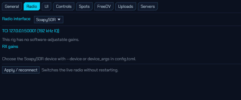
With the SoapySDR interface the tab shows the controls the device itself exposes, and nothing it does not:
- RX gains — one slider per gain element (dB, with the device’s own limits). A rig with no software-adjustable gains says so instead, as in the screenshot above.
- TX gains — transmit gain sliders, if the device has them.
- Antennas — an RX drop-down when the device has more than one receive
port, and a TX one when it has more than one transmit port. A LimeSDR
receives on
LNAH/LNAL/LNAWand transmits onBAND1/BAND2; a HackRF has a singleTX/RXport and gets no drop-down at all.
The antenna is remembered per band, everywhere it can be chosen. Whichever front end you are on — an Icom’s ANT1/ANT2, an RSPdx’s A/B/Hi-Z, a LimeSDR’s LNA ports — the socket you pick is remembered against the band you picked it on, and put back the next time the dial crosses into that band. It survives a restart, and a memory channel stored while the radio is on a socket carries that socket with it and selects it again on recall — and EDT on the channel is where you change your mind about which one that should be (2.12). A band you have never chosen a socket on is left exactly where the radio already is, so nothing moves a relay for you until you have said what belongs on that band. Each VFO remembers its socket too, which is what lets you keep A and B on different sockets at the same end of one band; a change of band hands the choice back to the band (2.5).
- Stream — Sample rate and Baseband filter, listing the values this device says it accepts. Both default to leaving things as they were: the rate falls back to the app-wide
sample_rate, and the filter to whatever the driver picks for itself (usually derived from the rate, and usually right). Changing either reopens the radio.- **
settings** — every setting the driver publishes, drawn from what it says about itself: a HackRF's `bias_tx`, an RTL-SDR's `direct_samp`, an RSP's `rfnotch_ctrl`. sdroxide does not know what any of them mean, which is the point — a radio it has never heard of still gets the controls its driver author wrote. Switches appear as tick boxes, settings with a fixed set of values as drop-downs, and everything else as a text box; hover a name for the driver's own description. These take effect on the running radio as soon as you touch them, and are remembered for the next start.
A driver is free to refuse a setting — a key that moved between versions, a hardware revision that lacks it, a value it will not take. It says so in a notice rather than failing quietly, and the rest are still applied.
Whichever ports and gains you pick are remembered in session.json and set
again the next time you start, and re-applied if the radio drops out and the
engine reconnects it — a freshly opened device is on whatever port and gains its
driver defaults to, which need not be the feedline you were listening on or the
levels you had settled on against your own noise floor. A gain stage your
current front end does not have is kept rather than discarded, so switching back
to the radio it belongs to brings it back; one outside this device’s range is
clamped to what it can do. To pin the ports at start instead — on a headless
server, where nobody is at the machine to pick — use --antenna and
--tx-antenna; --probe lists the names a device offers.
A remote client gets this tab too, filled in from the server’s own
radio.json rather than from any file beside the screen: the gains, the
antennas and every setting the interface has, applied to the running device and
saved where the radio is (8.4). What stays behind is the
choice of interface and the buttons that scan a bus or test an address — those
ask about a machine, and from a remote client it would be the wrong one.
The cyan heading above the gains names the device that is open right now, not
the one selected — which is why the screenshot still reads
TCI 127.0.0.1:50001 (192 kHz IQ): the interface has been switched to SoapySDR
but Apply / reconnect has not been pressed yet.
Which device to open comes from config.toml (device_args) — for example
device_args = "driver=hackrf"; an empty value uses the first device found. You
can also override it on the command line with --device. The sample rate is on
this tab, but --rate still wins over it, and an untouched Stream section
leaves the app-wide sample_rate in charge exactly as before.
Why your VFO does not sit in the middle of the waterfall. On a SoapySDR device with a wide enough span, sdroxide parks the hardware LO a quarter of the span above the dial and tunes down to the signal in software, so your VFO marker sits a quarter of the way in from the left rather than dead centre. That is deliberate. Most SoapySDR hardware mixes straight to baseband, which piles its own LO leakage, converter offset and flicker noise up at the centre of the span — precisely where the dial would otherwise be. A narrow mode never notices, because that junk falls outside the demodulator’s passband, but an FM discriminator has no passband to hide behind: on a HackRF One tuned straight onto a strong FM broadcast station, the offset measures about the same amplitude as the station itself, and what comes out of the speaker is static. Moving the LO clear of the dial is worth about 14 dB of recovered signal over simply subtracting the offset, so sdroxide does both. Narrow streams (under 1 Msps) and devices whose analogue filter is too narrow to reach the offset keep the LO on the dial and rely on the offset subtraction alone.
The whole span is still yours — three quarters of it now sits above the dial, which is where band activity usually is — and the LO moves only when the dial would otherwise leave the usable span or come too close to the centre. Other interfaces (RTL-SDR, HPSDR, TCI, CAT) are unaffected: none of them puts the dial on a dirty LO.
6.2.2 CAT radios (serial control + USB audio)
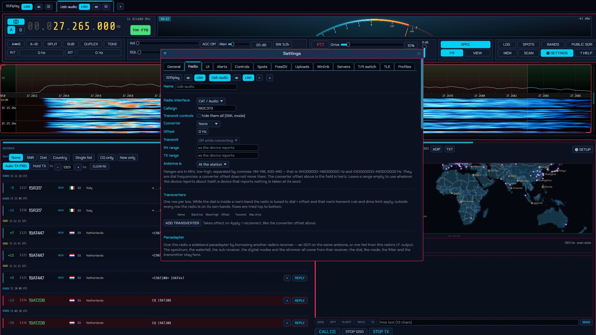
A CAT radio is controlled over a serial port while its audio arrives over a USB sound card — chosen at the foot of this tab under Radio audio (sound card), separately from your computer’s own speakers and microphone (6.1).
Radio audio (sound card) — below the control settings, and only for this interface: every other backend carries its audio in the same stream as its I/Q and needs no card at all.
- From radio (RX) — the capture device carrying the radio’s receive audio.
- To radio (TX) — the playback device carrying your transmit audio to the radio.
- Apply / reconnect — reopens the rig with the chosen cards, without a restart.
- Receive audio gain — a fixed trim, in decibels, on everything this radio sends to the speakers, on top of the volume control. Leave it at 0 dB unless the radio is quiet at full volume: the volume rail’s top is the audio as it arrives, so it can turn a radio down but never up, and some transceivers’ USB sound output sits well below full scale — a Yaesu on CAT is the usual case. Go up 6 dB at a time. Too much clips: the audio is limited at full scale rather than allowed to wrap round, so overdoing it sounds harsh rather than loud. Recordings are taken ahead of it and are not affected, which is the same rule the volume control follows. It takes effect as you type — no Apply.
All four belong to this radio, which is why they are here rather than on the
General tab where they used to be (issue #474): a station running two rigs at
once is running two sound cards at once, and one pair of pickers on a shared
page could only ever describe one of them. In radio.json they are
radio_audio_in, radio_audio_out and rx_audio_gain_db, and they always
were — only the page they were edited on was wrong.
Device names include the manufacturer, model, ALSA card id, and USB id — for
example C-Media Electronics Inc. USB Audio Device, USB Audio [Device · 0d8c:0012]
— so two identical adapters can be told apart. Where the operating system itself
hands out the same name twice (Windows and macOS do, and two Icoms are two of
the same USB codec) the second one carries a short tag of its own, as in
USB Audio CODEC [#a3f1]. The tag comes from the device rather than from the
order it was found in, so it stays the same across restarts and a radio keeps
the sound card it was given.
IQ needs a stereo device. IQ format requires a two-channel capture interface (I and Q). A mono USB audio adapter cannot carry IQ; if you pick one for IQ, sdroxide refuses it and shows a warning banner. Use a stereo line-input interface for IQ, or choose Demod audio.
On a PipeWire system, the desktop audio server can hold a USB radio codec’s
capture device open, which intermittently blocks sdroxide from opening it (the
symptom is silent receive and a “waiting for spectrum” panadapter). For a
sound card dedicated to the radio, the reliable fix is to tell WirePlumber to
stop managing that card, leaving it for sdroxide. Create a drop-in such as
~/.config/wireplumber/wireplumber.conf.d/51-radio.conf that disables the
card, then restart WirePlumber. See troubleshooting.
Sound format — how the radio’s audio is interpreted:
- Demod audio — the radio sends already-demodulated (mono) audio. The panadapter shows a narrow slice of the audio band mapped to RF, whose width is set by Panadapter BW. This is the common case for rigs like the Xiegu X6100.
-
IQ (stereo) — the radio sends a stereo IQ signal (I on the left channel, Q on the right). This gives a full panadapter but requires a stereo capture device (see the note above).
The radio’s dial is the centre of that panadapter, and every way of tuning the active VFO moves the radio, with the display recentring on it: a click on the spectrum or a spot box, the frequency readout, the keypad, a memory or band recall, wheel- and drag-tuning on the panadapter, and anything arriving from WSJT-X or another program over the rigctld or TCI server — down to a single-hertz step, so the radio’s readout and sdroxide’s never disagree. That agreement is not cosmetic: CW keyed from the panel goes out through the radio’s own keyer, and a microphone keyed at the radio transmits wherever its dial is, so a dial left behind by a click would put those overs on the air at a frequency the panel no longer shows. Turning the radio’s own VFO knob is the same contract from the other end: its synthesiser moves, and with it everything the radio is sending us, so the whole display follows. Only tuning that has no dial of its own stays inside the span the radio is sending: shift-click placing the sub receiver, or parking the inactive VFO.
On any other kind of receiver — an SDR, or a transceiver paired with one under Panadapter — none of this applies: the window is the receiver’s own, so every kind of tuning moves sdroxide’s receiver inside it and the hardware is only retuned when the frequency would leave the span.
With no control cable, all of the above is off. A radio that never answers on its control port has a dial only its own knob can turn, so sdroxide stops trying to command it and tunes inside the I/Q the radio is already sending instead — a click, the wheel or a drag moves the receiver within that span, exactly as on an SDR, and the window stays where the radio put it. Set the band on the radio itself, then type its dial frequency into the readout here once to line the panadapter’s labels up with it; from then on everything inside the span is yours. sdroxide says so on screen when it starts, so if you do have a cable, that notice is the sign to check the port, the baud rate and the CAT family. Plug the cable in or switch the radio on later and the dial is picked up as soon as the radio answers, without restarting.
Transmit is the same on both. The sound format describes what the radio sends; what it takes back is always audio into its playback device, which the radio modulates itself. So the drive level, the mode and the sideband that goes on the air are the radio’s own settings, commanded over CAT, on a quadrature rig exactly as on a demod-audio one.
The mode travels in both directions on either sound format, subject to the Mode control setting below: change it on the radio and sdroxide follows on the next poll, change it in sdroxide and the radio follows. On a quadrature rig sdroxide is the one demodulating, so the mode is not what shapes what you hear — but it is what the radio’s own display shows, and it is the sideband the radio will transmit on, so the two readouts are not allowed to disagree. What sdroxide does not send a quadrature rig is the filter width: on that path the passband is sdroxide’s own, and narrowing the radio’s I.F. against it would cut into the span it is sending. A demod audio rig gets both, because there the radio’s filter is the only one in the path.
Neither the dial nor the mode is imposed when the port opens — sdroxide adopts whatever the radio is already sitting on rather than retuning it out of a saved session.
I/Q sample rate (IQ format only) — how fast the radio’s I/Q sound card is run, and so how wide the panadapter is. A quadrature stream spans its whole sample rate, centred on the dial, so 48 kHz shows ±24 kHz either side of the frequency you are tuned to, 96 kHz shows ±48, and 192 kHz shows ±96. Nothing else changes: the audio, the demodulators and the decoders all work exactly as before, on a receiver that now has more band to pick from.
The sound card decides what it will do. A card that cannot run at the rate you pick is opened at the nearest rate it does have, which leaves the panadapter narrower than you asked for — a startup log line says so when that happens, because a card quietly refusing looks identical to a setting you mis-clicked. Most USB codecs sold for radio work do 96 kHz; 192 kHz is common but not universal, and 384 kHz is rare.
A faster card is also more work for the computer, and the margin is not generous: at 192 kHz there is a quarter as much time to empty the card between callbacks as there is at 48 kHz. A machine that cannot keep up drops captured samples, and the two things reading the stream disagree completely about how much that matters — the panadapter is unaffected (every block it transforms is still real signal, so the waterfall looks perfect) while the demodulated audio, which has to be continuous, breaks up into clicks and stutters. Audio breaking up while the waterfall still looks right is that symptom and not a DSP fault; sdroxide logs a warning naming the count when it happens. If you see it, come back down a rate.
That warning counts only what is dropped while you are receiving. A rig that transmits through its sound card is not being listened to for the length of the over, so its capture buffer overflows every time you key — those frames say nothing about your computer and are not counted. A warning that arrives once per transmission, and only then, is not this. The same warning on a demod audio rig names no rate to come down to, because that path is always opened at 48 kHz: there it means something else on the machine is taking the CPU away.
Changing this takes effect on Apply, without restarting.
Invert spectrum (Swap I/Q) (IQ format only) — mirrors the panadapter about the tuned frequency, for a radio that carries I and Q the other way round on its sound card. Which channel a quadrature rig calls I is a wiring convention, and one that disagrees with sdroxide’s (I left, Q right) looks perfectly healthy until you read the waterfall: it fills with convincing signals that are all on the wrong side of the dial, and SSB comes out on the opposite sideband. Swapping the two cables at the sound card fixes it just as well — this is the same fix without the soldering iron. Leave it off unless you see that symptom.
It applies to receive only. Transmit hands the radio one real audio signal for it to modulate, and a real signal has no sideband to invert.
Every signal drawn twice, once either side of the dial? That is not a setting either of the two above can fix — it means the card is not carrying I/Q at all. A radio sending demodulated audio down a stereo cable puts the same signal on both channels, and two identical channels make a real signal, whose spectrum is symmetric about the dial by definition: there is no second sideband to recover, so Invert spectrum has nothing to swap and I/Q correction has no imbalance to trim. sdroxide notices it within a second of the stream starting and says so in the log window. Either put Sound format on
Demod audio, which is what the card is actually carrying, or switch the radio to its raw I/Q output — in PowerSDR that is the Direct I/Q box in the VAC setup.
I/Q centre offset (IQ format only) — how far above the radio’s own dial its I/Q output is centred, for a rig whose receive I.F. has been moved off zero. Leave it at 0 unless you have turned such a setting on in the radio.
A quadrature rig normally puts its local oscillator on the dial, which piles the
mixer’s DC offset, the LO’s own leakage and the sound card’s zero-hertz junk on
exactly the signal you are listening to — the permanent spike in the middle of
the waterfall. Rigs that offer a way out move the I.F. instead: on an Elecraft
K3/KX3, MENU:RX SHFT set to 8.0 rather than NOR puts the oscillator 8 kHz
from the dial, which takes the dial off the spike (and, per Elecraft, stops a
strong nearby SSB or AM station being detected in the receiver). Set this field
to 8000 to match, and the panadapter and everything reading from it stay on
frequency.
The radio goes on displaying and transmitting the real frequency, so this is not a converter offset — the field under Radio → Converter retunes the radio itself, which is the one thing a shifted I.F. does not do, and using it here moves the whole display off by the offset instead of correcting it. Nothing typed here is ever sent to the radio: it only says where the samples arriving on the sound card sit, and the stream is shifted back onto the dial as it arrives. The rig’s DC spike lands the offset away from the dial, where it can be seen and ignored.
If signals end up at twice the offset from where they belong, the sign is the
other way round for your radio — enter -8000 instead. Receive only, as above.
A QMX is the other kind of case, and sdroxide fills this field in for you:
its receiver is a superhet with a 12 kHz I.F., so its synthesiser sits 12 kHz
below the dial and everything on the sound card is 12 kHz above the middle
of the span. Picking the QRP Labs family with the sound format on IQ sets
this to -12000 and the sample rate to 48 kHz, which is the only rate that
card runs at. One thing the single figure cannot follow: in CW the radio moves
that I.F. by a further ~700 Hz so that zero-beat stays zero-beat, so if you run
the panadapter with the radio in CW, add it by hand. In Digi — where a radio
used as an I/Q front end normally sits — there is nothing to add.
The offset can be set up to half the I/Q sample rate either way, which is as far as the digitised window reaches: past that the dial is outside what the card is recording at all. Raising the rate raises that ceiling with it.
IQ correction (Cancel mirror images) (IQ format only) — cancels the copy of every signal that appears on the other side of the tuned frequency, and the permanent spike in the middle of the waterfall. On by default; leave it on.
A radio’s I/Q output is two analogue paths — the receiver’s quadrature mixer, then two channels of a sound card — and they are never quite equal in gain, nor exactly 90° apart. What that leaves is a mirror: a signal 8 kHz above the dial appears again 8 kHz below it, typically 30 to 40 dB down. That is weak enough to overlook on a quiet band and strong enough to be a problem on a busy one — it looks like a station, it decodes like one on FT8, and it moves when you tune, which is exactly what a real signal does. Radios with a pair of front-panel balance trimmers are adjusting this by hand; radios without them are why sdroxide does it in software.
Nothing needs setting. The correction measures the imbalance off whatever the receiver is hearing — noise will do — and converges in a second or two, then tracks it. It cannot measure one case, and does not try: a band that is a mirror image of itself, which is two equally strong carriers either side of the dial or an AM/DSB signal centred exactly on it, looks identical to an imbalance. Blocks like that are discarded rather than learned from, so the correction goes quiet instead of going wrong.
Turn it off when you are listening to AM tuned dead on the carrier: that carrier is DC, so it goes with the spike and the envelope detector distorts without it. Tuning a kilohertz off is the other answer, and the better one. It is also worth switching off for a moment to settle an argument about a weak signal — one that disappears with the correction on was the mirror of something else.
DC notch (IQ format only) — how much of the middle of the span to high-pass away, in hertz. 0 by default, which is not “no DC blocking”: the correction above already removes the offset with a corner a few tens of hertz wide, and that is enough for almost everyone.
Raise it for a radio whose centre spike is broader than the offset underneath it — some sound cards put mains hum and converter noise in the first couple of hundred hertz, and no amount of DC removal touches that. What this does is widen the corner: a first-order high-pass, 3 dB down at the figure set and falling further in below it, up to 500 Hz.
It costs signal, and it is worth knowing where. The notch is centred where the radio’s I/Q is centred, which is the dial itself unless I/Q centre offset has moved it — so whatever you are tuned to goes into the hole with the spike. A CW note at 600 Hz is inside a 600 Hz setting. If the middle of the span is unusable rather than merely untidy, the real fix is the offset above: shifting the radio’s I.F. moves the signal away from the spike instead of digging a crater around it.
Both settings take effect on Apply, without restarting, and both are receive only.
Serial (CAT) settings, in the order they appear:
- Serial port — the radio’s CAT serial port. On Linux, USB-style ports
(
/dev/ttyACM*,/dev/ttyUSB*) are listed first. -
CAT family —
Xiegu,Icom,Yaesu,Kenwood,Elecraft,ELAD,QRP Labs,RS-HFIQ,Hamlib rigctld (network), orflrig (network). The eight native profiles drive one manufacturer’s rigs each; the last two talk to an already-running daemon — Hamlib’srigctld, or flrig — and cover everything else (see rigctld address and flrig address below).Five of the native ones speak ASCII commands ending in
;and look interchangeable, but they are not. A Kenwood driven as a Yaesu rejects every retune and keys up without unkeying, becauseTX0;— Yaesu’s unkey — is a transmit command on a Kenwood. An Elecraft driven as a Kenwood tunes and keys correctly and then goes out on the wrong sideband in every digital mode, because DATA is a mode there (MD6/MD9) rather than a flag beside one. An ELAD driven as a Kenwood tunes and keys and then reads every meter wrong, because its S-meter, its SWR and its power control are all ELAD’s own commands on ELAD’s own scales. A QMX driven as a Kenwood has its power meter written to as though it were the power control, andMD8— a mode on a Kenwood — puts it into SWR Tune. Pick the right one. -
rigctld address (Hamlib rigctld only) —
host:portof a running Hamlibrigctld.127.0.0.1:4532is the daemon’s own default, on this machine. Start one with, for example,rigctld -m 2028 -r /dev/ttyUSB0 -s 38400, where-mis the Hamlib model number for your radio (rigctl -llists them).This is the catch-all, for a radio none of the native families covers. It reaches the frequency, mode, PTT, transmit power, S-meter and SWR — and nothing else: no keying from the rig’s own text buffer, no receive filter, no per-model meter scales. Where one of the families above fits your radio it does more, so prefer it. The serial settings disappear when this is selected, because the link is a socket;
PTT methodDTRandRTSkey nothing over one, so useCATorVOX. -
flrig address (flrig only) —
host:portof a running flrig.127.0.0.1:12345is flrig’s own default, on this machine; the port is under flrig’s Config → Setup → Server, and its XML-RPC interface is on whenever flrig is running.The other catch-all, and the one to pick where flrig already drives your radio well: like the Hamlib option it talks to a daemon rather than the radio, but through flrig’s own per-model driver, and on a number of rigs flrig’s handling of the transmit power and the filter is the more faithful of the two. It reaches the frequency, mode (by the rig’s own mode names, learned from flrig at connect), PTT both ways, transmit power — in whole watts, scaled so the Drive slider spans the rig’s own range: 100 % is everything the radio has, whatever that is (a KX3 with a KXPA100 behind it goes to its full 110 W, not to 100), and 0 % is the least it will do — the receive bandwidth (flrig snaps a dragged filter to the nearest one the rig has), the S-meter, and the SWR and power-out meters while transmitting. It also shares the rig: flrig’s own panel and every other program pointed at flrig stay live alongside sdroxide.
What it does not reach: flrig’s interface has no RIT/XIT clear (only split), so unlike the native profiles a rig left with RIT on offsets the dial unseen — check the radio’s own display. Power is whole watts, so levels under 1 W cannot be asked for. CW under
Rig keyer (CAT)goes through flrig’s cwio keyer — a DTR/RTS line on a serial port configured inside flrig itself (its CW keying dialog), not the rig’s internal keyer — and keys nothing until that port is set up there. The serial settings disappear here too, andPTT methodDTR/RTSkey nothing over a socket: useCATorVOX. - Radio (Elecraft only) — not a setting, just a reminder of what the profile covers: the K3 command set, which the K3S, KX3, KX2 and K4 all answer. How many watts the Drive slider spans is read from the rig itself when the port opens, so there is nothing to choose.
- Radio (QRP Labs only) — likewise: QMX, QMX+ and the QDX-series radios that
share their command set all answer the one profile, and the radio names itself
and its firmware version when the port opens. Two notes sit under it: the
Baud setting below is ignored (a QMX serves its own virtual COM ports over
USB, so the rate means nothing at either end), and with Sound format on
IQa third says that I/Q mode is switched on at the radio for you. - Radio (RS-HFIQ only) — HobbyPCB’s RS-HFIQ, the 5 W HF transceiver, and the shortest profile here because it is the whole of the radio’s command set (issue #383). See the note below.
- Baud, Data bits, Parity, Stop bits — the serial line settings (for example 19200 8N1 for a Xiegu X6100).
- Force RTS / Force DTR — hold a control line high or low (some interfaces need this).
- PTT method —
CAT,DTR,RTS, orVOX(how transmit is keyed). - Mode control —
CAT(sdroxide sets the radio’s mode to match) orRadio controlled(you set the mode on the radio and sdroxide follows). -
Digimode mode — what to switch the rig to for a mode sdroxide modulates through its sound card:
USB(the plain sideband),DIGI(the rig’s DATA / PKT position, so the over is taken from the data input with the microphone path’s speech processing out of it), orRadio controlled(leave the rig’s mode alone). It covers every digital mode, SSTV included, and CW sent asSound card (MCW); it overrides Mode control for those, because the sideband a digital mode needs is not a matter of taste.SSTV and RADE are the two modes whose sideband follows the band — both are phone emissions and keep phone practice, LSB on 160, 80 and 40 m and USB on 60 m, 30 m and above — so there
DIGImeans the rig’s DATA position on that sideband (LSB-D / DATA-LSB on the low bands, USB-D above them). SSTV-FM is not part of this: it modulates an FM carrier, so the rig is put in FM (with the data input selected where the family has one) whatever this is set to. - CW keying — where CW you send comes from,
Rig keyer (CAT)orSound card (MCW). See below. -
Poll rate — how often (Hz) sdroxide reads the rig’s frequency, mode and meters. This is the half of the control link that runs from the radio: turn the rig’s own VFO knob, or change its mode on the front panel, and the readout, the band and the panadapter follow within one poll. It applies to every CAT family.
It is also the whole of the control traffic sdroxide generates, and on a fair number of radios that traffic is not free. A modern Icom is a USB hub with the CI-V port and the sound card behind it — an IC-7300 enumerates a 4-port hub carrying a CP2102 serial bridge and a PCM2901 audio codec, both at full speed — so every frame asked for on the control port is bus time the audio inside the radio does not get, no matter how good the cable outside it is. The symptom is dropouts in the received audio that look exactly like a DSP fault and are not one.
The default of 2 Hz is half a second behind the knob and quiet enough to stay out of the audio’s way. Raise it where the control port is its own device — a separate USB-serial adapter, a network
rigctld— and it competes with nothing. Lower it if the radio’s audio breaks up: the setting covers the meters as well as the dial, so turning it down really does turn all of the traffic down.The rate is the dial’s. The mode rides along with only every fourth poll — no faster than once a second and no slower than once every five — because it is a setting somebody changes a few times in an evening, and asking for it at the speed a VFO knob turns spends a frame every time on the same answer. Changing the mode on the radio’s front panel therefore shows up a beat behind the dial would, which at the default is within two seconds.
Icom only: if CI-V Transceive is switched on in the radio’s own menu (SET → Connectors → CI-V), the rig broadcasts its dial and its mode the instant either moves. sdroxide watches for those broadcasts, and the first time it sees one it stands the dial poll down to a three-second safety net — the knob is then followed faster than any poll rate could manage, for none of the traffic. Nothing needs setting at this end; with transceive off, polling carries on as before.
It arms on the radio volunteering a broadcast, which is whenever the radio gets round to it, so the log says when it happens: “the radio reports its own dial and mode (CI-V transceive is on); standing the dial poll down to a safety net”. If you are measuring control traffic against audio dropouts, that line is what tells you which of the two rates you were measuring.
It gives the claim up again on evidence, not on a stopwatch. Switch Transceive off mid-session and the next thing to move the radio — the VFO knob, a memory recall, a band button — turns up on the safety-net poll as a change nothing announced, and the full poll rate comes straight back with a matching line in the log: “the radio moved without reporting it (CI-V transceive is off); polling the dial at the configured rate again”. A timeout would have been wrong here: at idle nothing changes, so no broadcasts arrive to keep the claim alive, and every rig that simply had nothing to report would be put back on a full poll — which is exactly the case the stand-down exists for.
What it will not do is give the claim up because a read and a broadcast crossed on the wire. Turning the VFO knob broadcasts every step, so a poll issued in the middle of one comes back describing a dial that has already moved on; an answer that disagrees within a second of a broadcast is put down to that rather than to a silent radio.
- Send command (Kenwood only) — which transceiver generation keys the rig
when PTT method is
CAT. The two disagree about what theTXparameter means, nothing on the wire tells them apart, and there is no value that is right on both — so it is a setting rather than a guess:TS-2000 style (TX;)— TS-480, TS-570, TS-870, TS-2000, and any Kenwood with no separate data input. The ordinary send, on the main band.TS-590 style (TX1;)— TS-590S/SG, TS-890, TS-990. DATA SEND, which keys with the ACC2/USB audio input live. On these rigs the plain send selects the microphone instead and mutes the audio sdroxide transmits — the classic “it keys but nothing goes out” fault.
The default is
TS-2000 style, because the two mistakes are not equally bad: a TS-590 set wrong transmits silence, while a TS-2000 set wrong transmits on the sub-band — another band entirely. - Radio model (Icom only) — which Icom, for the two things CI-V does not
do the same way on all of them:
- The transceiver address, which is filled in from the model. Every one ships with a different one, and a frame sent to the wrong address is simply ignored — a radio that answers nothing at all, with no error anywhere to say why. It is only overwritten when you change the model, so a rig you have deliberately re-addressed stays as you set it.
- DATA mode. On CI-V, USB and USB-DATA are the same mode byte; a second command tells them apart, and not every model has it. Without it a digital-mode over goes out through the microphone input, with the rig’s speech processing and SSB transmit filter in the path — wide, compressed, and short of the passband the decoder at the other end wants.
Otherleaves the address to you and sends no DATA-mode command at all, which is the only safe answer for a radio this list has never been told about. The IC-7000 is listed but has no such command either: its data input is selected at the radio. -
Antenna (Icom only) —
ANT1/ANT2, the radio’s own antenna selector: the same setting as the ANT button on its front panel. The row only appears on a radio that has a selector, because that is not something CI-V states: every Icom speaks one dialect, an IC-7610 answers the antenna read and an IC-705 refuses it, so sdroxide asks when the port opens and draws the row only if an answer comes back. The socket it is on is read back at the same time, so the control opens showing the truth rather than a remembered guess, and the choice is remembered per band like every other antenna in sdroxide. A radio with four sockets (the IC-785x line) is offered the first two; select ANT3 or ANT4 at the radio, and sdroxide shows no socket rather than claiming the wrong one.One thing CI-V cannot be asked is how many sockets a radio has, and one model turns out to answer the read without having a selector at all: an IC-7300MK2’s antenna command switches its receiving antenna and nothing else, so it gets the Receive antenna row below and no socket row. That fact comes from the model you picked above rather than from the radio.
The same control is on the main window’s RIG box, as ANT — see 2.7. You do not have to come here to change socket.
-
Receive antenna (Icom only) — the radio’s separate receiving antenna, switched into the receive path or out of it: an IC-7300MK2’s RX ANT IN/OUT, an IC-7610’s RX ANT. The main aerial stays on transmit either way, which is what makes it a different thing from the socket above rather than a third socket.
The row appears only where the radio has the connector, and it says so by the shape of its own answer: the antenna reply carries that setting behind the socket where there is one to carry, and the socket alone where there is not.
It is deliberately not remembered here, and not carried in a memory channel. The radio recalls it per band itself, so sdroxide reads it back after every band change — including one you made at the radio — and shows what the radio says. Ticking the box is the only thing that moves it, which is the point: a receive-only input switched out behind your back is an aerial gone quiet with nothing on screen to say why.
Also on the main window’s RIG box, as RX ANT — see 2.7.
-
Radio power (Icom only) — On and Off switch the radio over the CI-V link, the way RS-BA1 and wfview do. This is not sdroxide’s own LINK switch in the tab strip, which closes sdroxide’s end and leaves the radio running: this one leaves the interface open and switches the radio off, which is the way round that matters, because the link has to survive for the switch back on to reach anything. Over the network that is what Network Control keeps awake; over a serial cable it is the radio’s CI-V port, which stays powered on a set switched off at the front rather than unplugged. Powering on sends the run of wake-up bytes Icom’s own documentation asks for, sized to the port’s baud rate, because a sleeping radio’s control receiver loses the first bytes of anything sent to it.
Two buttons rather than a switch, deliberately: a radio that is off answers nothing, so there is no position to read back, and a toggle could only ever show you your own last click. This is sdroxide’s only on/off control; the LINK switch is sdroxide’s own end of the connection.
These two are on the main window’s RIG box as well, as PWR ON / OFF — see 2.7.
- Radio ID (hex) — the CI-V address, for Icom and Xiegu radios.
-
Show the radio’s spectrum scope (Icom only) — stream the radio’s own scope sweep over the CI-V link and draw it as the panadapter, the same way the Icom LAN interface does. On Demod audio this is the only picture of the band the rig can give: the audio it sends has already been through its filter, so the audio-band panadapter is never wider than that filter however far you zoom out — which is exactly the “the spectrum barely covers one broadcast station” complaint. With the scope on, the main panadapter becomes the radio’s sweep, centred on the dial and as wide as Scope span, and the full-band strip (the WIDE button) carries it too. The digital modes switch back to the audio band, which is where FT8 and the keyboard modes place their signals.
It needs the radio set up for it, both under MENU » SET > Connectors > CI-V: CI-V USB Baud Rate =
115200, and CI-V USB Port =Unlink from [REMOTE]. Then set the Baud above to 115200 to match. Below that rate the sweeps physically do not fit down the link, so sdroxide declines to ask for them and says so in the status line rather than burying every poll and PTT under sweep fragments.Off by default, unlike the LAN interface, and deliberately: over USB the sweeps ride the same bus inside the radio as its sound card (see Poll rate above), and a sweep stream is far more traffic than the polls. If the received audio starts breaking up with the scope on, this box is the first thing to try clearing. Everything the LAN chapter says about the scope applies here too: it is the radio’s picture — click it to tune, but nothing can be demodulated or skimmed inside it — its levels are auto-ranged because Icom publishes no dB scale, a stopped scope restarts itself after a few seconds, and Scope span also puts it into centre mode (changing the radio’s own screen, which is the price of the wider view).
Scroll down for Apply / reconnect, which reopens the rig with the new settings.
When you key the radio itself
Pressing the microphone button on the transceiver — or its foot switch, or letting its VOX or its own keyer key it — is an over sdroxide never asked for, and it is treated as one. sdroxide notices it within about a fifth of a second and follows it: the meter goes to transmit and reads the SWR of that over, and comes back to receive when you let go. It does not join in. No audio from the computer goes anywhere near it, and a PTT arriving in sdroxide meanwhile — the on-screen button, a key binding, a program on the rigctld or TCI server — is refused with a notice rather than queued, so an over cannot start the instant you release the microphone.
That refusal is only ever for as long as your hand is on the button. It is also fail-safe in the direction that matters: if the control port goes quiet while the radio is keyed, sdroxide gives up on it after two seconds, says so in the log, and goes back to receive rather than sitting there refusing to transmit.
Which radios can report it, and how:
| Family | Read | Notes |
|---|---|---|
| Icom / Xiegu | 1C 00 |
The read form of the command that keys the rig. |
| Yaesu | TX; |
|
| Elecraft | TQ; |
|
| Kenwood | IF; |
One character of the status reply, taken by position. A rig whose status string is a different length reports nothing rather than a guess. |
Hamlib rigctld |
t |
Whatever the daemon’s own backend supports. |
| flrig | rig.get_ptt |
Whatever flrig’s own driver for the rig supports. |
| ELAD | — | No such read; an over keyed at the radio goes unnoticed. |
| QRP Labs | TQ; |
A command of its own, like Elecraft’s. |
These reads need to be verified against real radios. Each is taken from the manufacturer’s published command reference, and the end-to-end behaviour was proven against a simulator written from the same documents — which demonstrates that sdroxide does the right thing with the answer, not that the question is the right one to ask. The Icom read is the one to trust furthest: it is the read form of the command sdroxide already keys Icoms with. The Kenwood read is the one to trust least, because it alone depends on a field position rather than a command of its own.
A family that answers nothing at all simply leaves this feature switched off, and nothing else about the radio changes — which is also what a wrong guess degrades to, thanks to the length check on the Kenwood reply.
The one thing this does not do is hold the station transmit interlock across radios: with two radios configured, keying one at its own microphone does not lock the other out. Only overs sdroxide keys take that interlock.
CW keying. A transceiver told to be in CW keys its own transmitter: it does
not modulate what arrives at its sound card, so a keyer’s sidetone sent there
reaches nothing at all. Rig keyer (CAT) — the default — therefore hands the CW
panel’s text to the radio and lets the radio’s own keyer send it, which is the
only route that puts CW on the air from a rig that is in CW. There is no PTT
around it: the rig switches to transmit for the length of the message itself.
On Sound card (MCW) the same rig is held on a sideband and the tone is
modulated like any other audio, so it needs the rig’s own mode to be a sideband
too — and on a radio sdroxide cannot command the mode of, that is a setting on
the radio itself (6.2.21). The failure
is worth recognising, because nothing reports it: the tone sounds, the send
decodes back into text, the transmit indicators behave, and the air is silent.
What that needs on the radio:
- Break-in on. sdroxide asserts it on Yaesu (
BI1) with every message, because with break-in off the keyer runs into the sidetone and never keys the transmitter. On Kenwood the same switch isVX, which is the VOX switch in every mode except CW — so sdroxide sends it only once the rig has reported that it is in CW, rather than risk turning VOX on under a live sound card. On Icom it is16 47, sent with every message for the same reason: an Icom sends a message given to it by a computer only while[TRANSMIT]is on, an external TX switch is closed, or break-in is on, and the first two are front-panel things an operator working the radio over a network cannot reach — which is what left CW on a remote IC-9700 doing nothing at all (issue #282). It is set to semi break-in, and never down from full: the setting is read once when the link opens, so a rig you run in QSK is left in QSK. Either way the radio is left in break-in afterwards, as it is on the other two families. If you key CW with Mode control set toRadio controlled, turn break-in on at the radio yourself. Elecraft and QRP Labs need none of this: aKYmessage keys the transmitter itself there, the way a recorded message does. - The panel’s WPM is sent to the rig’s keyer (Yaesu, Kenwood, Elecraft and
QRP Labs
KS, Icom keyer speed), so the speed button in the CW panel is the speed on the air. Farnsworth spacing is the sidetone keyer’s and has no equivalent in a rig’s keyer, so it does not apply on this route. Elecraft’s keyer stops at 8 and 50 WPM, so the panel’s ends are clamped to those. A QMX’s bottom end is held at 5 WPM for a different reason: on that radio zero words per minute is not a slow keyer, it is Straight Key mode. - A longer break-in delay, and consider SEND ON RETURN. The rig takes the text a message at a time and switches to transmit for each one, so how often it drops back to receive is set by two things sdroxide does not control: your break-in (QSK) delay, and how much text arrives at once. Typed live, that is a message per word. SEND ON RETURN in the CW panel (2.14) holds the line until you press Return and then sends it whole, which is one switch of the relay for the sentence.
-
Yaesu only: keyer memory 1 is used as scratch. Yaesu has no streaming keying command — text can only be stored and played back — so sending CW overwrites whatever you had stored in CW memory 1. Kenwood, Elecraft and QRP Labs stream the text straight to the keyer (
KY), 24 characters at a time, and leave your stored messages alone.A Yaesu keyer holds two kinds of memory on the same five channels: the ones recorded from the paddle, and the ones written as text. Which playback command reaches the text differs by model — the FT-710 is the one radio of the family that inverts it — so sdroxide asks the rig what it is (
ID;) at connect and keys accordingly. Getting this wrong is silent: the rig transmits whatever was recorded on that channel, or nothing at all, while the CW panel colours your text as sent. - The Drive slider is the power CW goes out at. Nothing sdroxide sends reaches the air here — the rig keys its own transmitter — so the level of the audio going into its sound card means nothing in CW, and the transmit level is the rig’s own power control, commanded over the same serial link before each message (2.10).
Sound card (MCW) is the other route: the keyed sidetone goes out as audio, a
tone on the sideband sitting at dial + pitch — which is exactly where the
panadapter draws the stations, so a clicked station is answered on its own
frequency. Because a rig in CW would ignore that audio entirely, selecting CW
with this route follows the Digimode mode setting instead of switching the
rig to CW: USB or DIGI command that sideband, Radio controlled leaves the
rig on whatever mode you parked it in. It is here for radios whose keyer
sdroxide cannot drive — on a Xiegu G90, set CW keying to Sound card (MCW)
and Digimode mode to Radio controlled, and park the rig in its U-D
position, exactly as for FT8: the G90’s U-D cannot be selected over CI-V, and
its other modes take audio from the microphone rather than the interface. What
you give up against a rig in CW is its CW filtering; the sideband filter is
what does the selecting.
Note (Kenwood): at connect sdroxide turns the rig’s auto-information off (
AI0), clears RIT and XIT, and selects VFO A for receive, which is also how this family turns split off. sdroxide carries RIT, XIT and split on the dial itself, and it tunes VFO A — so a rig left on VFO B or in memory mode would answer every frequency read and ignore every retune.
Note (Kenwood meters): the S-meter and the transmit SWR come from the radio’s own meters, and both are read against the model, which sdroxide asks for at connect (
ID;). It has to:SMandRManswer with a count of lit bars, and full deflection is 20 bars on a TS-2000, 30 on a TS-590 and 70 on a TS-890 — so the same reading of 12 is a 3:1 fault on one rig and very nearly flat on another. Scales are carried for the TS-480, TS-590S/SG, TS-890S, TS-990S and TS-2000.On a model sdroxide has no scales for, the S-meter still reads — on a generic straight line, so approximately — and the SWR meter stays blank rather than showing a number with no meaning behind it. The log line
Kenwood CAT: rig reports model ID …carries the number, which is what would let the model be added.
Note (Elecraft): at connect sdroxide does the same — auto-information off, clarifier cleared, RIT, XIT and split off — and two things besides. It puts the rig into
K20;K31;, because a K3 left in K2 command mode 1 or 3 by whatever ran before reports DATA and DATA-REV as LSB and USB, so it would look like a radio that never leaves SSB. And it asks the rig what it is (OM;), which is where the Drive slider’s scale comes from: 110 W with a KPA3 or a KXPA100 fitted, 12 W without one. Until that answer arrives the slider is the QRP scale, so the first moments after connect can only ask for less power than the radio has, never more.A K3 whose
CONFIG:CW WGHTis set toVFO OFSshifts its own dial by the CW pitch whenever the mode crosses into or out of CW, so that zero-beat stays zero-beat. That is useful at the radio and invisible over CAT, so sdroxide re-asserts the frequency behind every mode command it sends an Elecraft — otherwise an operator who asked for 14.050 would find themselves transmitting six hundred hertz away with nothing on screen to say so. Nothing on the wire reports how that menu entry is set, so the re-assert is unconditional; on a rig already on the right frequency it costs one frame and changes nothing.Setting the mode sends
DT0;after the mode itself, which pins DATA to DATA A — the sound-card path. It has to:MD6;on its own restores whichever of the four sub-modes that band was last left in, and on a rig used for RTTY that is the K3’s own FSK keyer, which has nothing to send. For the same reason sdroxide follows the rig into DATA only when it reports DATA A; left in AFSK A, FSK D or PSK D it reports no mode at all rather than one the two would then argue about.
Note (the filter width on a CAT rig): the width control in the receive panel is sent to the radio. It has to be: there is no demodulator on this side of a CAT rig — the audio arrives already filtered, and already levelled by an AGC that has ridden the interference down — so narrowing it here would only cut what the radio had let through, long after the damage was done.
What each family can express differs, and where sdroxide cannot say a passband exactly it leaves the radio’s filter alone rather than guess:
- Elecraft —
BW, a real bandwidth in 10 Hz steps, every mode. The rig quantises it to what the mode allows.- Icom — the filter-width index, which follows a formula rather than a per-model table: 50–500 Hz in fifties then 600–3600 Hz in hundreds on a sideband, and 200 Hz–10 kHz in two-hundreds in AM. FM picks its filter with the mode, so nothing is sent there.
- Kenwood —
FWin Hz in CW; on a sideband the rig has no width at all but a pair of cuts (SL/SH), which is exactly what the panel’s two filter edges are, so they map across directly. Index tables are carried for the TS-480, TS-590S/SG and TS-2000; on any other model, and in AM and FM, the rig’s filter is left alone.- QRP Labs — nothing. A QMX reports the width its mode implies (
FW;— 3.2 kHz in Digi, 300 Hz in CW) and has no command to change it, so the panel’s filter edges shape the display only.- Yaesu —
SH, an index into a table the model holds, so the rig is asked what it is (ID;) at connect. Tables are carried for the FT-891, FT-991/991A, FTDX10, FTDX101D/MP and FT-710. On any other model, and in AM and FM, the rig’s filter is left alone. The NARROW switch is set first where the generation has one, because otherwise the rig quantises the request into the other half of its table.Where a width is not an exact entry in the rig’s table it is rounded up, so the radio’s filter is never quietly narrower than the one on screen — a filter that is too narrow presents as a signal that simply is not there.
Note (Yaesu): the S-meter and the transmit SWR come from the radio’s own meters (
SM0andRM6), because on a CAT rig there is nothing else to measure — the audio arriving at the sound card has already been through the radio’s filter and AGC. Both are read against the FT-991 calibration Hamlib uses for the whole current generation, so an FT-891, FT-991/991A, FTDX10, FTDX101D/MP, FTDX1200/3000/5000 all read alike.On an FTDX3000 or FTDX5000 with the tuner in line the rig only answers the SWR read when its own meter is already set to SWR; there set the front-panel meter to SWR, or the reading stays at the bottom of the scale.
Note: on a Yaesu USB interface the Enhanced port is the CAT port configured above. The Standard port is the one whose RTS/DTR lines are wired to PTT and KEY; sdroxide does not use it, and
PTT methodDTR/RTSset on the Enhanced port will not key anything. UseCATthere.
Note (Icom over USB): if the dial and the waterfall follow the radio but PTT and TUNE do nothing, the link is fine and the keying is not. Check PTT method first:
CATkeys with a CI-V command and always works on a rig that is answering, whileDTRandRTSonly key if the radio’s own USB SEND setting has been assigned to that line (an IC-7300 leaves it off, so those two do nothing at all out of the box), andVOXkeys nothing until VOX is on at the radio. The Radio ID (hex) must also be the rig’s CI-V address — 94h on an IC-7300, B6h on an IC-7300MK2, 70h on a Xiegu X6100 — though a wrong one stops the frequency working too, so it is rarely the answer here. When the radio answers the key-down with a refusal, sdroxide says so in the log: the radio refused the transmit command.
Note (ELAD): this family is the FDM-DUO and FDM-DUOr. Set Baud to match menu 70
CAT BAUDon the radio, which ships at 38400 — the radio has only 9600, 38400, 57600 and 115200, and at any other rate the link is silent both ways rather than merely unreliable. The rig’s own S-meter and SWR are read (SMandWR) and its transmit power appears on the Drive slider as the nine fixed steps the radio has — 0.3, 0.5, 1, 1.2, 1.5, 2, 3, 4 and 5 W — rather than as a continuous control. Transmit input beside the family selects where the radio takes transmit audio from: leave it onUSB audiounless you talk into the radio’s own microphone.Antenna picks which of the radio’s two rear sockets the receiver listens on — its
ANcommand, menu 31ANTENNAS, theANT 1 2indicator on its display.RTXis one antenna doing both jobs;RX onlymoves receive to the second socket and leaves transmit on RTX, which is the arrangement for a receiving antenna with the beam still on the transmitter. It applies immediately and is remembered, and until you have picked one it shows the rig’s own setting, read when the port opens.There is no DATA mode on an FDM-DUO, so digital modes go out as plain USB or LSB and which input the radio transmits is the Transmit input setting rather than anything the mode says. There is no text keyer either —
SWplays one of the ten messages stored in the radio — so the CW panel cannot key it over CAT; use the radio’s own key or paddle, or menu 37CW INset toKey+DTR.If your FDM-DUO’s receive USB cable is also plugged in, the ELAD FDM-DUO / FDM-S (USB) interface (6.2.16) drives the whole radio at once — a real wideband panadapter instead of an audio-band slice — and covers this CAT link itself. This family is for a DUO reached by its CAT cable alone. Neither has been verified against a radio.
Note (QRP Labs): this family is the QMX, the QMX+ and the QDX-series radios that share their command set. The Baud setting does not apply — the radio serves its own virtual COM ports over USB, so the rate means nothing at either end — but which port does: a QMX offers up to three, and only one of them is the CAT port you want. If nothing answers, try the next one.
⚠️ Never open a terminal program on the same port. A QMX takes a carriage return as an instruction to leave CAT and become a terminal, for the rest of the session. sdroxide never sends one; a terminal emulator will, on the first Enter you press.
The transmit power is set at the radio. There is no CAT command for it, so the Drive slider only reaches the level of the audio going into the sound card, and in Digi that does not change the power at all — the radio measures the frequency of what you send it and synthesises the carrier itself. What the radio does report while transmitting is the SWR and the forward power it has measured, in real watts, and both appear on the meter.
Modes. The radio’s DIGI-U and DIGI-L are what sdroxide’s digital modes go out on (
MD6andMD9); CW and CW-R are both CW; LSB, USB and AM are themselves.MD8is not a mode — it is SWR Tune, a carrier into the radio’s own bridge — so sdroxide never asks for it, and a radio sitting in it is reported as being in no mode rather than in some sideband it is not on. A QMX has no FM position at all.CW goes to the radio’s own keyer (
KY), 24 characters at a time, at the speed the CW panel is set to (KS). Do not set that speed to zero: on a QMX zero words per minute is not a slow keyer, it is Straight Key mode, and sdroxide holds the bottom of the range at 5 for exactly that reason.SWR protection. On firmware 1.04.004 and later sdroxide reads the radio’s protection latch (
SR). If it has tripped, the radio will not transmit until it is reset at the radio — sdroxide says so in the log and deliberately does not reset it for you, because clearing a protection trip is a decision about an antenna.What the profile leaves alone: the receive filter (the radio reports the width its mode implies — 3.2 kHz in Digi, 300 Hz in CW — and offers nothing to change it with), and the RF and audio gains, which live in the radio’s own menus. Written from QRP Labs’ published CAT and operating manuals; not yet verified against a radio.
Note (RS-HFIQ): HobbyPCB’s RS-HFIQ is an I/Q transceiver, and that is what makes this the shortest profile here (issue #383). A quadrature detector and a quadrature modulator sit either side of a synthesiser running at four times the dial, so what the sound card carries is complex baseband centred on the operating frequency, in both directions. Everything a CAT command does on another radio — the mode, the filter, the modulation, the demodulation — is sdroxide’s here, and the serial link is left with the two things that really are the radio’s: where to put the oscillator, and whether to transmit.
Selecting the family fills in three things that are facts rather than preferences, so leave them: Sound format goes to
IQ (stereo), PTT method toCAT, and the port to 57600 8N1 — the firmware’s one rate, with no menu to change it, so sdroxide pins it when the port opens. The centre offset is set to zero, because the oscillator is on the dial. Set IQ rate to whatever your sound card is actually running at; that is what makes the panadapter as wide as it is.The frequency command covers 3–30 MHz and nothing outside it. Ask for more and the radio answers
Frq out of range.and stays where it is — the dial springs back within a poll, and the log says why.What there is nothing to reach. No mode, power, filter, squelch, meter or keyer command exists, because the radio has none of them: transmit power is set at the radio, the S-meter is sdroxide’s own measurement of the I/Q, and CW goes out as a keyed tone through the transmit chain like any other audio. (The firmware has an internal CW generator on
*X2; its own documentation says do not use it, and sdroxide never does.)Written from HobbyPCB’s published Interface Commands page. Not verified against a radio, and one thing in particular is a guess: the page says what each query reports but not how the reply is framed, so sdroxide accepts a bare number, one with the command echoed in front of it, and either line ending. If the dial readout does not follow the radio, that is the thing to report.
Note: RIT, XIT and split are driven over the same serial link, by moving the radio’s dial — see 2.6. Set them in sdroxide rather than on the radio: sdroxide clears the rig’s own copies on connect so the two can’t stack up.
Which bands are offered. CAT carries no band table, so sdroxide cannot tell an HF-only FT-891 from an FT-991A on 70 cm or an IC-9700 on 23 cm. Rather than guess, it leaves every band live and lets the rig answer: ask a radio for a band it does not have and it simply declines over CAT, which sdroxide reports in the log. The real limits on transmit are your licence — the amateur-band gate, which follows your region (6.1) — and the rig itself. If you would rather sdroxide held the dial to the radio you actually own, state an RX range and TX range at the top of this tab.
6.2.3 HPSDR (network radios)
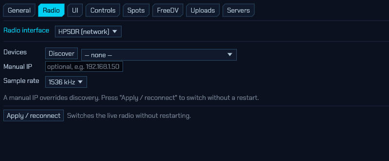
With the HPSDR (network) interface, sdroxide reaches an OpenHPSDR (Hermes/Metis-family) Ethernet SDR over the LAN — no sound card or serial port involved:
-
Devices / Discover — scan the local network for HPSDR devices and pick one from the list. Both protocols are driven: Protocol 1 (the Metis framing used by the Hermes Lite 2 and the older Metis/Hermes boards) and Protocol 2. Which one a board speaks is detected when the connection opens. A board is listed by the gateware’s own name with the commercial one beside it —
Angelia (ANAN-100D),Orion (ANAN-200D),Saturn (ANAN-G2)— because those are the same radio under two names and only one of them is on the front panel.A board found here that then never starts — the connection opens, the waterfall stays empty, the link is dropped after five seconds and the whole thing repeats — is almost always a board that is still streaming to somebody else: another program on the network, or a session of this one that ended without being able to stop it. The gateware sends to whichever host started it and ignores a start command from anywhere else while it is running, and it reports itself as in use in the discovery listing and the log while that lasts. sdroxide sends a stop before every start for exactly this reason, and repeats the start command each second while nothing arrives, so a board in that state is normally reclaimed within a second or two (issue #365). If it is not, close whatever else is holding it — and check that UDP port 1024 is not blocked by a firewall.
- Manual IP — connect directly to a known address (for example
192.168.1.50), skipping discovery. A manual IP overrides whatever discovery found. - Sample rate — the DDC receive rate: 48, 96, 192, 384, 768, or 1536 kHz. Protocol 1 boards top out at 384 kHz. Wider rates give a wider panadapter span at more CPU/network cost.
- Receiver (DDC) — which of the board’s receivers this radio runs. A Protocol 2 board carries several independently tunable DDCs on one connection, so a second radio tab configured with the same address and DDC2 gives you a second band from the same board (§2.17) — the two radios share the Ethernet connection, and closing either leaves the other streaming. The transmitter belongs to the DDC1 radio. Sample rate, LNA gain and the filter board belong to the connection: whichever radio opens it first sets them, and later ones adopt them. A Protocol 1 board has DDC1 only and refuses anything else with a message saying so.
- LNA gain — the front-end gain of a Hermes Lite 2, −12 to +48 dB. It takes effect immediately, with no reconnect, and is remembered as the level the radio starts at. It is the only analogue gain the board has: too high and the ADC clips, which smears spurious signals across the whole band; too low and the receiver goes deaf. Start around +20 dB and work from there. The same control also appears as Gain next to the volume slider in the main window, and on the Device tab.
- Power amplifier — switches on the Hermes Lite 2’s onboard PA. On by default, and what you want unless an external amplifier is driven from the board’s low-power RF1 output. With it off the radio still keys — the T/R relay throws, the PTT line closes and any accessory board follows — but the antenna jack makes no power at all, and the relay is deliberately held in receive so the antenna connector stays on the receiver. Ignored on boards other than a Hermes Lite.
- Invert spectrum (Swap I/Q) — mirrors the board’s spectrum about the tuned frequency, on transmit as well as receive. On by default, because a Hermes Lite 2 needs it. Turn it off only if signals appear on the wrong side of the dial and nothing decodes: the giveaway is a waterfall full of convincing-looking traces while SSB comes out on the wrong sideband and FT8 returns no decodes at all (or a handful of CQs from callsigns that don’t match their grid).
-
Overload protection — wind the LNA gain back by itself while the board reports its ADC overflowing, and let it back up once it stops. Off by default, because it moves a control you set.
A Hermes Lite 2 samples the whole of 0–38 MHz onto one 12-bit converter with no mixer and no preselector in front of it. A broadcast station a band away can therefore drive it into overflow while the band you are looking at shows nothing wrong at all: the noise floor climbs, everything intermodulates, the decoders stop, and none of it is visible as a signal that is obviously too big. The board knows — the overflow flag is in the status bytes it sends with every frame — and this is what acts on it. The OVL light on the S-meter (2.9) follows that same flag whether or not the loop is switched on, so you can run manual gain and still see it happening.
Switching it on opens three settings:
- Step — how far the gain moves each time, 0.5 to 12 dB. One decibel is the step the board’s own gain register has.
- Attack / decay — how often the gain may come down while the converter is overflowing, and how often it may go back up once it has stopped. The two are deliberately a hundred times apart, and that asymmetry is the whole design rather than a tuning choice. Retreat immediately: every millisecond of overflow is a receiver full of intermodulation. Return slowly: whatever caused it — a neighbour keying, a broadcaster coming up at dusk — has usually not gone away, and a loop that recovered as fast as it retreated would spend the evening oscillating across the threshold. 100 ms and 10 s per decibel are the defaults, which is what PowerSDR’s Auto S-Att and N1GP’s HermesIntf have both used.
- Range — the lowest and highest gain the loop may use. The ceiling is what stops it deciding how sensitive your receiver should be; the floor is where you say that below some point the overload is somebody else’s problem and the answer is a filter, not another twenty decibels.
Nothing happens while you are transmitting. A board’s own transmitter leaks into its own receiver, and reading that as a receive overload would wind the gain down through every over and hand you a deaf receiver on unkey. The main window’s Gain rail reads the gain the board is actually running, so it follows the loop and you can watch what it does — the LNA gain slider on this page is the level the radio starts at, and the loop does not rewrite it. Every move it makes is logged with the running count of overflow reports — which is worth having on its own when you are trying to work out whether a preamplifier or an antenna is marginal (issue #362).
Only a Hermes Lite 2 has a front-end gain sdroxide can command, so this is a Hermes Lite feature today; the loop itself knows nothing about the board and will follow any front end that grows one.
-
Filter board — how the board’s seven open-collector outputs are driven. On a Hermes Lite 2 these are the J16 header; every other openHPSDR board has them too, Protocol 2 boards included (Odyssey 2, ANAN-G2, Saturn — before 1.6.5 nothing was sent on those at all, whatever this was set to). Leave this at None unless something really is connected. Those pins are general-purpose outputs, and operators also use them for amplifier PTT, antenna relays and transverter switching; driving them from band data would start operating whatever is wired there. (If what you want is an antenna relay that follows transmit rather than the band, that is the T/R switch tab — see 6.11 — which drives one over USB and sequences an amplifier with it.) There are three ways to drive them:
- N2ADR filter board — the low-pass filter follows the band you are on (the transmit band while keyed) and the board’s 3 MHz receive high-pass is switched in above 3 MHz.
- Alex / Hermes band code — the band goes out as a four-bit number on outputs 1–4 (160 m = 1, 80 m = 2, 60 m = 0, 40 m = 3, 30 m = 4, 20 m = 5, 17 m = 6, 15 m = 7, 12 m = 8, 10 m = 9, 6 m = 10), which is what an ANAN’s Alex board, a Zeus SDR, a HiQSDR and Quisk all expect. Outputs 5–7 stay off — they carry no part of the band code, and on those boards they are the spare pins operators wire to a preamplifier, an attenuator or a transverter.
- Custom — you state the words yourself in the table that appears below, described next.
Both presets follow the transmit frequency while keyed and the receive frequency otherwise, and this takes effect on Apply / reconnect.
These seven pins are external switching. A Protocol 2 board that has an internal Alex filter chain (an ANAN-100/200, an ANAN-7000/8000, an ANAN-G2) has that switched for it as well, and there is nothing to set: the transmit/receive relay, the band filters and the ANT1 jack follow the radio’s own frequency automatically. Note the radio’s own — with a transverter in front, the internal filters are set for the I.F. the board actually works on, while the open-collector outputs above follow your dial, which is the band on the air. Before 1.6.9 none of this was sent, so an internal Alex chain sat with every relay released.
-
Open-collector outputs by band — the table Custom opens: one control word per band, written in hexadecimal the way your hardware’s documentation states it, with bit 0 = output 1 and bit 6 = output 7. It is there for everything the two presets do not fit — an antenna switch, an amplifier’s band decoder, a transverter sequencer, a filter board with its own wiring.
Each band has two words. RX is asserted while you are receiving on that band and TX while the transmitter is keyed. Make them the same for a filter, which has to be in circuit both ways, and different for anything that belongs on one side of the changeover only — an amplifier’s key line, a receive preamplifier’s bypass. The outputs each word asserts are listed beside it, so there is no need to convert in your head. A band left at
0x00asserts nothing. The last row, Other, is everywhere outside the amateur bands — short-wave listening, and anything a transverter’s dial lands on that no band covers; without it a custom table would leave those frequencies unfiltered where a preset gives them the nearest filter it has.FILL FROM N2ADR and FILL FROM ALEX BAND CODE replace the table with what that preset would send on every band, which is how you configure a board that is nearly one of them: pour the preset in, then change the pins that differ. CLEAR puts every band back to nothing. The table is kept even while a preset is selected, so switching to one to compare and back again does not lose it.
What is driven is the seven open collectors, and only those. sdroxide does not send a genuine Alex board’s own 32-bit filter word on either protocol — the Alex / Hermes band code preset is that band code on the open collectors, which is what the boards listed above read. The Protocol 2 byte carrying these outputs is taken from the published field layout and has not been verified against a Protocol 2 board here; reports are welcome.
- Transmit buffer — how far ahead of real time transmit audio is fed toward the board, 10 to 500 ms, before sdroxide slows down to feed it at exactly the rate the board consumes it. That head start is the only thing covering a hiccup between one block and the next: a stall shorter than it is inaudible, a longer one empties the buffer and goes out as chopped audio. The 30 ms default is right for a wired LAN, where the link contributes almost no jitter of its own. Over WiFi or a VPN, where it does, raise this until the stutter stops — 100 to 200 ms is usually plenty. The cost is transmit latency: the same delay is added between speaking and transmitting, and between releasing PTT and the transmitter dropping. Unlike the Icom LAN setting of the same name, this is not a buffer inside the radio — OpenHPSDR has no such thing — so it only widens sdroxide’s own margin on this side of the network. Takes effect on APPLY, which reconnects to the board.
- PureSignal — adaptive predistortion: linearise the transmitter from a sample of what it actually emitted. Every amplifier compresses near its ceiling, and compression on a multi-tone signal — which is what SSB and every digital mode are — is intermodulation, landing either side of your transmission on other people’s contacts. Backing off is the traditional answer and costs most of the amplifier. Predistortion instead sends a deliberately wrong signal, bent by the inverse of the amplifier’s own curve, so what comes out is right; twenty-odd decibels of IMD improvement is the usual figure, and the amplifier keeps its power. See below for what it needs.
Receive is wideband IQ, so the full panadapter and the skimmers work.
PureSignal needs the transmit sample to reach the receiver. The board is commanded in duplex, so its receiver keeps running through an over — that is the feedback path, and there is no second receiver involved. What is needed is a directional coupler on the amplifier’s output and an attenuator after it, feeding an input the T/R switch does not take away on transmit. On a Hermes Lite 2 that means the IO board’s PureSignal jack (J10), with IO board RX input set to “IO board J9, PureSignal on transmit” so the board switches it in for the length of every over. A coupler into the radio’s own antenna jack will not do: the T/R relay disconnects the receiver there for exactly the period being measured.
Set the attenuation so the feedback is strong but well clear of clipping — a Stockton bridge is about 36 dB down across HF, and the reference feedback unit adds another 25 dB. Two things hold whatever it is fed:
- the correction table starts at unity, so a coupler that is not connected, a receiver that is deaf, or an alignment that never locks all leave the transmitter exactly as it would have been;
- and it cannot make the transmitter louder — the table is normalised at the top, so a compressing amplifier is linearised by taking small-signal gain away rather than by asking for more than full scale.
The S-meter says which it is. With PureSignal switched on, the meter face
carries a small PS readout in its bottom-right corner, opposite the
temperature: PS 4dB while the loop is locked and correcting (a * after it
means Hold is on), and an amber PS -- while it is switched on but has not
found the transmission in the feedback — which is the ordinary failure, and one
that is otherwise invisible, since an unlocked loop transmits exactly as it
would have with the feature off. Hover the meter for the match score behind it.
Nothing is shown at all on a radio that is not running a loop. The reading is
from the last over and stays put between them, which is when you want to read
it.
The log says the same thing at more length: while transmitting you get either “PureSignal is correcting N dB of compression” or “PureSignal has not found the transmission in the receiver’s stream”, every few seconds. Table steps is how finely the curve is modelled (32 is a sensible start) and Adaptation how fast it follows the coupler; slow is right, because it is averaging a curve that does not move out of a path that has noise in it. Hold stops it adapting and keeps what it has learned.
⚠️ Not verified against hardware. No amplifier has been on the end of this on a Hermes Lite 2. The processor itself is exercised against a simulated compressing amplifier and converges; that says the arithmetic is right, not that a real feedback path is what it expects. The safe failure — nothing coupled in, so nothing learned and the transmitter left alone — is the one it is built around, but treat the first over as an experiment and watch the log.
The radio’s own PTT input keys sdroxide too: a foot switch or mic button on the board’s PTT connector (a Hermes Lite 2’s CN4 jack) transmits exactly as the on-screen PTT button does, safety rails and all. It belongs to the DDC1 radio — the one that owns the transmitter — so a second radio tab on another DDC never keys on it. Currently Protocol 1 only.
An N2ADR HL2IOBoard on the accessory bus is found and driven automatically: there is nothing to switch on. sdroxide asks the bus whether one is there when it connects, clears its registers (they are static, and survive whatever program drove the board last), and from then on keeps it told of both frequencies:
- the transmit frequency, which is what an external amplifier, a transverter or a loop antenna switches bands on. It goes out as you tune, not at key-down, so the amplifier is already on the band before any RF appears.
- the receive frequency, sent as the board’s own one-byte band code, which its firmware can use to pick a receive antenna and preselector.
Updates are limited to one every half second, as the board’s documentation asks,
so a spun dial cannot flood its I2C bus — and the receive code covers a whole
band at a time, so ordinary tuning puts nothing on the bus at all. What the
board’s outputs then do is decided by the firmware you program into its
Pico: by design, sdroxide sends the frequencies and nothing else. Run with
RUST_LOG=sdroxide_hpsdr=debug to watch the board being found and each update
going out.
- IO board RX input — the board’s
REG_RF_INPUTS, and the one thing about it sdroxide cannot work out for itself. Leave it at Radio’s own input unless you have wired the IO board’s own SMA jacks: J9 can replace the radio’s receive input, and J10 is a PureSignal (transmit sample) input. Selecting IO board J9 with nothing connected to it leaves the receiver deaf. Takes effect on Apply / reconnect. Once it is set to one of the J9 choices, the three inputs also appear on the receiver’s ANT control and are remembered per band like any other receiving antenna — so a transverter band can listen on J9 while HF stays on the radio’s own jack. Left at Radio’s own input, no ANT control is shown, because an HL2 that has never used J9 has nothing there.
Help wanted — the HPSDR backend is not fully tested yet. If you own an HPSDR board, you can help by running with diagnostic logging and reporting what you see:
RUST_LOG=sdroxide_hpsdr=debug sdroxideUse
sdroxide_hpsdr=tracefor per-packet detail. The log shows discovery replies (board, protocol, MAC, raw bytes), the protocol and sample rate chosen, the first RX datagram’s structure, and a periodic RX throughput line (datagrams/samples/ksps). A plausible ksps close to the selected sample rate means the receive decode is working;no … I/Q datagrams after 3 sor an implausible rate points at a firewall or a wrong offset. On transmit, a Hermes Lite also reports why nothing is going out: the log states whether the onboard PA was switched on at connect, and warns if the board says its transmitter is inhibited or its transmit FIFO under- or overran. Please attach that output to a bug report.
6.2.4 TCI (network): ExpertSDR3 and Thetis
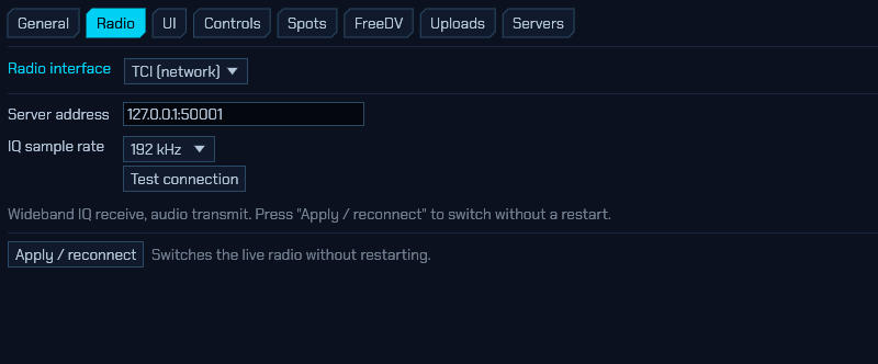
With the TCI (network) interface, sdroxide connects to a TCI server — such as Expert Electronics ExpertSDR3 or Thetis — over a WebSocket, receiving a wideband IQ stream and transmitting audio back:
- Server address — the TCI
host:port. The default127.0.0.1:50001is ExpertSDR3’s TCI listener on the same machine; enable TCI in the SDR software first. - IQ sample rate — the receive IQ stream rate: 48, 96, or 192 kHz.
- Receiver — which of the rig’s receivers this radio runs. A rig with two (a SunSDR2DX) can serve two radio tabs from one connection: one radio on RX1 and a second radio, same server address, on RX2, each independently tunable — sdroxide’s dials and the SDR software’s dials track each other per receiver (§2.17). The two radios share the WebSocket, so closing either tab leaves the other streaming. The transmitter belongs to the RX1 radio, and the IQ rate belongs to the connection: whichever radio connects first sets it. Asking for a receiver the rig does not have is refused with the count it reported.
- Test connection — verify sdroxide can reach the server and report what it found, without leaving the dialog.
Receive is wideband IQ (full panadapter and skimmers); transmit sends audio to the TCI server, which modulates it. Receive reaches 160 MHz and transmit covers HF, 6 m and 2 m, so a rig with a VHF section (a SunSDR2 PRO or DX, an MB1) keys up on 2 m without a stated TX range; the amateur-band gate keeps you inside your region’s allocation, and the rig declines anything it cannot do.
The SDR software has to be running. TCI is served by ExpertSDR3 or Thetis, not by the radio’s own firmware, so sdroxide connects to that program rather than to the transceiver. On a standalone set — an MB1, a Colibri, any SunSDR with a computer inside it — that program runs on the computer inside the radio, and it has to be started there with TCI switched on before anything can attach. This is not a limitation of sdroxide and no other TCI client avoids it: the same is true of the TS-480 CAT emulation those radios offer, which ExpertSDR3 also provides. A refused connection says as much in the message.
This is sdroxide acting as a TCI client. For the other direction — sdroxide acting as the rig so WSJT-X and friends can drive it — see § 5.8.2 Built-in TCI server.
6.2.5 RTL-SDR (USB dongles)
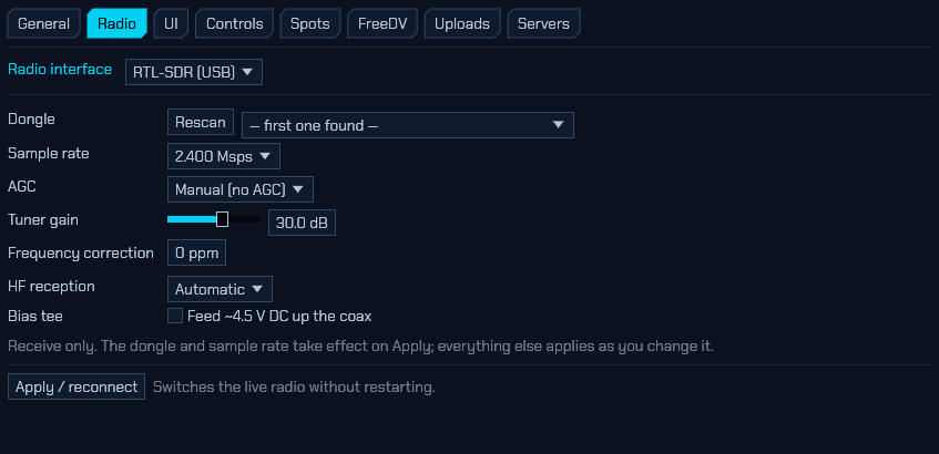
The RTL-SDR (USB) interface drives an RTL2832U dongle directly, using
sdroxide’s own USB driver. There is no SoapySDR and no libusb involved, so this
works in every build — including the standard Windows .msi and macOS .dmg —
with nothing extra to install beyond access to the device itself (see the
README’s RTL-SDR permissions).
Supported tuners are the R820T, R820T2 and R828D, which between them cover essentially every dongle still sold, including the RTL-SDR Blog V3 and V4. Older E4000 and FC001x sticks are not supported; sdroxide names the button it found and suggests the SoapySDR backend instead.
Receive only — there is no transmit path in this hardware.
- Dongle — which stick to open, by USB serial. Rescan re-lists the bus;
it opens nothing, so it is safe to press while receiving. Dongles ship with the
serial
00000001from the factory, so if you run more than one, program distinct serials (withrtl_eeprom) before you can pin them individually. Leaving this at first one found is fine with a single dongle. - Sample rate — the resampler reaches 225–300 kHz and 900 kHz–3.2 MHz, with nothing in between; the list offers only rates the hardware produces exactly. 2.4 Msps is the default and the highest that runs reliably on most hosts. 3.2 Msps is offered but drops samples on many machines.
- AGC — the tuner and the demodulator have independent automatic gain loops. Manual (no AGC) is the right setting for measurement and for weak-signal digital modes, where a gain loop pumping on a strong neighbour costs you the signal you were decoding.
- Tuner gain — applies immediately, no reconnect. The tuner has 29 discrete steps, so the value snaps to the nearest one it can actually produce.
-
Frequency correction — the dongle’s crystal error in parts per million. You do not have to guess it: run
RUST_LOG=sdroxide_rtlsdr=debug sdroxideand after about twenty seconds the log prints a line like
clock: 2400017 sps, +7.0 ppm — set this as the ppm correction. That is the number to type in. It is measured from the dongle’s own sample clock, which is the same oscillator the tuner runs from, so correcting it corrects your frequency readout too. - HF reception — the tuner itself starts at 24 MHz. Below that:
- an RTL-SDR Blog V4 upconverts in hardware, so HF simply works and the dial reads correctly with no offset to apply anywhere. On that path the tuner’s own tracking filter is switched out of circuit: what reaches it is the upconverter’s output, already filtered on the way in, so the preselector could only add insertion loss — and loss ahead of the LNA is noise figure, which is heard as a raised noise floor across HF;
- other dongles reach HF only by direct sampling the ADC’s Q branch, which is what a V3’s HF port is wired to. Automatic switches at the tuner’s own 24 MHz floor (with hysteresis above it, so a dial parked near the boundary does not flap); Direct sampling (Q branch) forces it; Off disables HF entirely.
Direct sampling reaches every HF band, including 17 m and 15 m — the two that sit above the ADC’s 14.4 MHz Nyquist limit and below the tuner’s floor, with nowhere else to go. They arrive in the ADC’s second Nyquist zone, the right way up, and you tune them at their real frequency like anything else. What you should expect is that whatever is at
28.8 MHz - dialcomes with them: there is no filter in front of the ADC, so 17 m carries 10.7 MHz and 15 m carries 7.726 MHz folded on top. Both are quiet enough that FT8 decodes; an HF preselector in front of the dongle removes them entirely. 12 m and 10 m are above 24 MHz, so Automatic gives them to the tuner and the question does not arise.Switching between the tuner and direct sampling re-initialises the tuner and briefly interrupts the stream.
-
IQ correction — clears the two artefacts every dongle puts in its own spectrum: the DC spike parked permanently on the centre of the span (the tuner’s local oscillator leaking back into its own mixer, plus the converter’s offset), and the mirror image each signal leaves reflected about that centre, because the I and Q paths never match exactly in gain and phase. Both are the receiver talking to itself; nothing on the antenna produces them. The R820T has no offset-tuning mode to move the oscillator out of the passband, so correcting the samples is the only way to get a clean centre.
sdroxide measures the imbalance from the samples themselves and needs no calibration: it converges in around a third of a second at 2.4 Msps and then tracks slowly, so it settles on the dongle rather than chasing a fading signal. Typical dongles gain 25–40 dB of image rejection from it.
On by default, and it applies the moment you tick it — no reconnect. Turn it off when you want to see the front end as it really is, or when measuring the receiver itself.
Two things are worth knowing. A spectrum that genuinely is symmetric about the centre — two equally strong carriers the same distance either side of the dial — looks exactly like an imbalance; sdroxide recognises a measurement no receiver could produce and holds its estimate instead of chasing it, so the worst such a signal does is stop the correction improving while it is there. And an AM station tuned dead on the dial has its carrier at DC as well, so the correction takes that carrier out along with the spike and the audio distorts: tune a kilohertz off it — the demodulator does not care — or switch the correction off.
- Bias tee — feeds roughly 4.5 V DC up the antenna coax for a mast-head preamplifier.
The bias tee puts DC on the feedline. Never enable it with a transceiver, a DC-grounded antenna, or a preamplifier powered from somewhere else on the other end of the cable. sdroxide turns it off again on a clean shutdown, and shows a standing warning while it is on, because the setting is remembered across restarts and there is otherwise nothing to tell you.
If the dongle is unplugged, sdroxide notices within a few seconds and reconnects by itself when you plug it back in — no need to press Apply. A dongle left streaming by a program that was killed rather than closed is reset automatically on the next open, so it does not need physically replugging either.
6.2.6 SmartSDR (FlexRadio network radios)
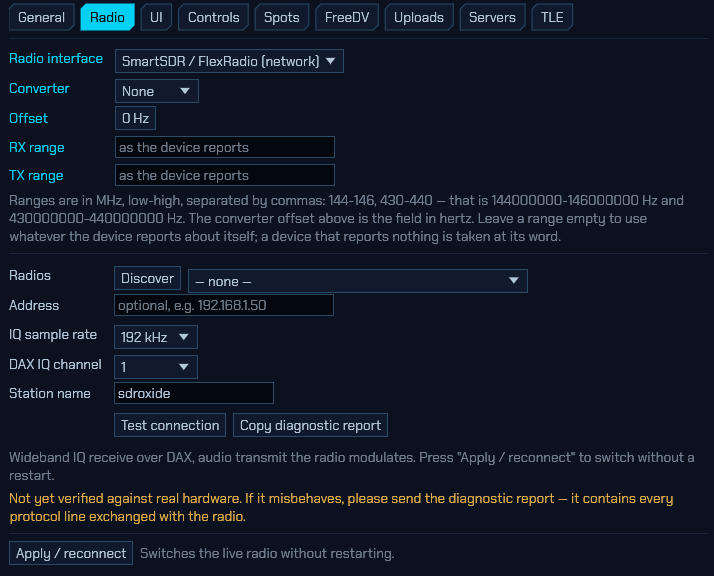
With the SmartSDR / FlexRadio (network) interface, sdroxide drives a FLEX-6000 or FLEX-8000 over the LAN. It connects as a GUI client on TCP 4992, creates a panadapter and a DAX IQ stream, and receives raw complex baseband from it — so the panadapter, the waterfall, the skimmers and every digital mode are sdroxide’s own, working from the radio’s samples rather than from a picture the radio already drew. Transmit sends audio over a DAX TX stream, which the radio modulates.
- Radios / Discover — a FlexRadio announces itself on the local network about once a second, so Discover listens for a couple of seconds rather than probing. A radio already claimed by another GUI client is listed but greyed out unless multiFLEX is enabled on it.
- Address — overrides the selection above. Radios reached through a router or a VPN never broadcast to you, so those have to be entered by hand.
- IQ sample rate — 24, 48, 96 or 192 kHz. 192 kHz is the radio’s maximum for a DAX IQ stream, and therefore the widest span this interface can show; it is not a limit sdroxide imposes. Nor is there a setting that gets round it: binding a DAX IQ channel to a panadapter makes the radio set that panadapter’s span to the DAX IQ rate, so the two are one number. A wider view of the band has to come from the radio’s own panadapter picture, which is what SmartSDR draws — run it alongside if you want one; the two clients coexist (see Two clients, one identity below).
- DAX IQ channel — the radio has four. Change this only if something else on the network already holds channel 1; the radio refuses the same channel twice.
- Station name — shown against this session in the radio’s client list. The radio also remembers a client by it and restores that client’s slices, so renaming makes the radio treat sdroxide as a new one.
- GUI client ID — the identity the radio files those restored slices under. Leave it empty and sdroxide derives one from the station name, which is stable across restarts but not unique: every sdroxide that kept the default station name derives the same one. See Two clients, one identity below.
- Invert spectrum (Swap I/Q) — mirrors the radio’s I/Q about the centre of the panadapter. Off by default, which is how a FLEX-6600 was verified. Try it if receive audio is unintelligible on USB and on LSB and nothing decodes, while the waterfall looks entirely convincing: that is what a mirrored stream looks like, and it is the one fault with no other symptom (issue #368, reported on a FLEX-8400M). Applies on Apply / reconnect.
- Network MTU — the largest datagram the radio may put on the wire, 1450 by default, which is what SmartSDR itself asks for. Lower it if the radio reaches you through a VPN or a tunnel with a smaller MTU: the spectrum rides UDP, and a path that drops IP fragments delivers nothing rather than delivering less.
- Test connection — checks the radio answers without registering as a GUI client, so it will not disturb a SmartSDR session already running. It also does not exercise the streaming path, which is a separate thing that can fail — see No spectrum below.
- Copy diagnostic report — see below.
Tuning moves the radio’s own slice, so its front panel and any second client
follow your dial rather than the other way round. TX power and TUNE power
command the radio’s rfpower/tunepower, and SWR and forward power come back
from the radio’s meters while you transmit.
Two clients, one identity. A FlexRadio identifies a GUI client by a UUID,
and settles two clients arriving with the same one by disconnecting whoever had
it first — reporting duplicate_client_id and handing the newcomer their
slices. Because the default identity is derived from the station name, and the
station name defaults to sdroxide, two sdroxide installations on one radio
arrive holding the same UUID, as do two windows of one installation. Left alone
that is not an eviction but a tug-of-war, each side reconnecting and throwing
the other off every few seconds.
sdroxide asks the radio who is already connected before it registers, and takes a one-session identity instead of evicting anyone it finds holding its UUID. If the radio evicts it anyway, it remembers that and reconnects transiently rather than fighting back. The cost either way is the radio’s session restore — a transient identity is one the radio has never seen, so it has no slices filed under it. Set a GUI client ID of your own (any UUID will do) to keep the restore and still be distinct from every other sdroxide.
Panadapters are a fixed resource. A DAX I/Q stream is centred on a panadapter, so sdroxide needs one — and the radio has only so many: two on a FLEX-6400, four on a 6600 and up, shared with whatever SmartSDR has open. A radio also restores a GUI client’s panadapters when that client comes back under an id it has used before, so the one from your last sdroxide session is usually still waiting.
sdroxide takes that one up again rather than asking for another, and removes it on the way out. When every panadapter on the radio is in use anyway — SmartSDR with two open on a 6400, say — it borrows one instead of refusing to receive: that panadapter’s span and centre follow this receiver while sdroxide is connected, and it is left alone at shutdown because it belongs to somebody else. The log and the diagnostic report say when that has happened. Close a panadapter in SmartSDR if you would rather sdroxide had one of its own.
No spectrum. The control link is TCP and the spectrum is UDP, so a radio can answer everything you ask it and still send you nothing. If the panadapter stays empty while the frequency readout tracks the radio, suspect the UDP path. On a computer that has never run SmartSDR, its own firewall is the usual answer: SmartSDR’s installer adds a rule for itself and sdroxide arrives without one. A VPN comes next, then an MTU smaller than the Network MTU setting.
Unintelligible audio. Two faults sound the same and nothing on screen tells
them apart: a receive chain running at the wrong sample rate, and a mirrored
spectrum. The diagnostic report’s --- streams --- section settles the first —
each DAX I/Q stream carries a line stating the rate it is measured to be
delivering against the rate its packets claim, and flags them when they
disagree. If those two agree, try Invert spectrum above for the second.
sdroxide says so on connect when nothing arrives, and the diagnostic report’s
--- streams --- section is where to confirm it. It opens with a count of the
datagrams that reached the machine at all, which separates the two silences: zero
means the radio’s UDP never got here and the fault is outside sdroxide, while a
non-zero count with no streams listed means it did arrive and sdroxide could not
read it — a bug worth reporting.
One case sdroxide repairs by itself: some firmware ignores the UDP port a client asks for and streams to 4991, FlexLib’s own. When the radio refuses that request sdroxide listens on 4991 too and says so in the report. It takes that port only in that case, so SmartSDR can still be started alongside on the same machine.
Receive covers 30 kHz to 54 MHz, and to 165 MHz on the models with a VHF receiver (the 6600, the 6700 and the 8000 family). On those, transmit is offered on 2 m as well as HF and 6 m — a FLEX’s own PA stops at 6 m, but a transverter on the XVTR port transmits at the band the slice is showing, and sdroxide cannot see SmartSDR’s transverter table to tell the two apart. Without a transverter the radio simply declines the key-down.
Help wanted — this backend has not been verified against real hardware. It was written from the published wire format and tested against a simulator, which proves the bytes are self-consistent but not that a FLEX agrees with them.
Every session records a protocol trace — each control line in both directions, the first packet of each VITA-49 stream, and per-stream packet and loss counters. It is always recording, so there is no log level to set in advance and nothing to reproduce twice: press Copy diagnostic report and paste it into an issue. That report is what makes a fault diagnosable by somebody who does not own the radio.
If you do not have a FLEX either, you can still exercise the backend: a wire-level radio simulator ships in the source tree. Run
cargo run -p sdroxide-smartsdr --example sim, then point this tab at127.0.0.1:4992.
6.2.7 PlutoSDR (ADALM-Pluto)
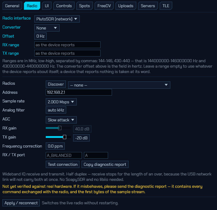
An ADALM-Pluto — the AD9361/AD9363 learning radio — driven directly over IIOD, the protocol its on-board daemon speaks on TCP port 30431. sdroxide implements that protocol itself, so there is nothing to install: no SoapySDR, no libiio, no driver package. It is in every build, including the standard Windows and macOS packages.
Wideband IQ receive and transmit.
A Pluto is a network device, even on a USB cable. This surprises people, so
it is worth stating plainly: plugging the Pluto in does not create a serial port
— it creates a network adapter. The radio takes 192.168.2.1 on that link
and your computer takes 192.168.2.10. That is why this tab asks for an address
rather than for a serial number, and why a Pluto on your Ethernet LAN is
configured in exactly the same way as one on your desk.
- Radios and Discover — asks the network for IIO devices (
_iio._tcp, which is what the Pluto’s own daemon advertises) and tries192.168.2.1directly. The direct try matters: multicast across a USB gadget link is exactly the sort of traffic a host firewall drops without saying so, and the address works even when the announcement never arrives. Each answer is opened and identified, so nothing is listed on the strength of an announcement alone. - Address — overrides the selection.
192.168.2.1is the default; a hostname (pluto.local) or ahost:portworks too. If you have used libiio before:ip:192.168.2.1is accepted, and ausb:URI is refused with an explanation, because this backend reaches the radio over the network the USB cable already provides. - Receiver — which of the AD9361’s receive chains this radio runs. A 2R2T-capable board — a Pluto+, or a rev. C Pluto unlocked to two channels — can serve two radio tabs from one box: one radio on RX1 and a second, same address, on RX2, each with its own antenna (§2.17). Unlike a TCI rig or an HPSDR board, the chains are not independently tunable: one local oscillator serves both, so retuning either radio moves both, and both panadapters follow. What RX2 buys is a second antenna on the same spectrum — receive diversity, comparing polarisations, or A/B-ing two antennas live — not a second band. The radio’s title says shared LO as a reminder. The transmitter belongs to the RX1 radio, and a stock 1R1T Pluto refuses RX2 when it connects, with a message naming what it found.
- Test connection — opens the radio, reads what it says about itself, and reports the model, the firmware version, and the tuning range this particular board has. Worth pressing once (see AD9363 vs AD9364 below). It does not start a stream.
-
Sample rate — the AD9361 reaches 61.44 Msps; the USB network link does not. 2 Msps of 16-bit I/Q is already 64 Mbit/s before framing, which is most of a USB 2.0 link, so the list stops where it does. Anything above 3.84 Msps is marked, and is realistic only over Ethernet. Takes effect on Apply / reconnect.
A stock Pluto cannot go below about 2.084 Msps. With the AD9361’s internal FIR decimator bypassed — which is how the radio arrives, and how sdroxide leaves it — the lowest rate the button’s clock tree can produce is 25 MHz ÷ 12. The rates under that are still offered, because a board someone has loaded a filter into can honour them, but on an ordinary Pluto they are rounded up and the connection message says so. They are marked in the list.
- Analog filter — the AD9361’s baseband filter, or
auto, which opens it to nine tenths of the sample rate. Wide on purpose: the receiver parks its oscillator a quarter of a span off your dial to keep signals clear of the DC spike a zero-IF radio has, and a filter narrower than that offset would cut off exactly the part it moved them to. If you narrow this by hand and the radio seems to get worse around the dial frequency, that is why. - AGC — four modes, because the AD9361 has four and they behave differently on the air. Slow attack is the default and suits SSB and CW, where a fast loop pumps on every syllable. Fast attack suits signals that appear suddenly and at very different strengths. Manual is the setting for measurement and weak-signal digital modes. Hybrid is a digital loop with an analog fast-attack safety net. (SoapySDR can only say “AGC on” or “AGC off”; this is one of the reasons the native backend exists.)
-
RX gain — 0–71 dB, applied as you move it. It only reaches the radio when the AGC is in manual: in the other modes the AD9361 owns that register and refuses the write outright, which is why the slider greys out. A value you set in manual is remembered and reapplied the next time you switch back, so changing AGC mode does not lose it.
Both of those are per chain on a two-channel board: the AD9361 keeps a gain register and a gain-control mode for each, so RX2 has its own of both and its AGC mode is set alongside RX1’s when the radio opens. If a chain is ever found somewhere else — another program moved it, or a firmware boots one in an attack mode — the gain write is not simply lost: the mode is put back where you asked for it and the gain sent again.
- TX gain — negative, because the AD9361 states transmit level as
attenuation:
0 dBis full output and−89.75 dBis as close to off as the part gets. Applied as you move it. On connect the transmitter is set to its quietest first and your value applied second, so nothing the previous program left in the attenuator is ever live. This is the hardware level, and it is not the Drive slider on the Transmit module: Drive scales the samples sdroxide sends, TX gain sets how loudly the radio plays them, and the two multiply (2.10). - Frequency correction — reference error in parts per million, applied by
sdroxide to every frequency it asks for. It is deliberately not written to
the radio’s own
xo_correction, which is persistent and would outlive the session and surprise the next program to open the radio. Run withRUST_LOG=sdroxide_pluto=debugand the log prints the measured clock error after about twenty seconds — that is the number to enter. - Duplex — whether the AD9361 runs both directions at once (FDD, how a Pluto boots and what sdroxide has always left it in) or one at a time (TDD). Leave it on FDD unless you want the PTT pins below: TDD is what those key from, and it rules out Full duplex. Takes effect on Apply.
- PTT pins — which pair of the Pluto’s four GPO test points follows the radio, for keying an external amplifier, LNA or transmit-receive switch with no host software in the loop. Off, GPO0 = RX, GPO1 = TX, or GPO2 = RX, GPO3 = TX. Picking a pair puts the radio in TDD whatever Duplex says. See Keying an external amplifier, below. Takes effect on Apply.
- Buffer size — how much the radio holds before each transfer, in complex samples, with the airtime and byte count it works out to shown beside it. The default of 32768 is about 16 ms at 2 Msps: long enough that the per-transfer round trip is not the bottleneck, short enough that a retune is not visibly late. Halve it if the log reports the receive socket being replaced (see When the receive stream stalls, below) — a smaller transfer is both less likely to be caught by a hiccup part-way through and quicker to make good afterwards. Raise it to trade retune latency for fewer round trips. Takes effect on Apply.
- RX / TX port — the AD9361’s
rf_port_select. A stock Pluto wires one of each (A_BALANCEDandA), so leave these empty unless you have a board that does not. The ANT control only offers the ports the board will actually switch to: each is tried once as the radio connects, and a Pluto whose device tree locks the port — every stock one — offers just the port it is on. The transmit-monitor loopbacks are never offered (issue #314). While the AGC is in one of its attack modes the main window’s Gain slider is greyed out, since the AD9361 ignores a gain written then; set the AGC to Manual to use it (issue #417).
AD9363 or AD9364. A stock Pluto is an AD9363 and covers 325 MHz–3.8 GHz; a great many have had the well-known firmware change applied, which turns them into an AD9364 covering 70 MHz–6 GHz with a 56 MHz filter. sdroxide does not ask you which you have and does not guess — it reads the limits off the device every time it connects, so the band buttons and the transmit gate follow the radio you actually own. Press Test connection to see which it reported. (If a firmware publishes no limits at all, sdroxide says so rather than quoting the fallback figures as fact.)
70 MHz is not the floor any more. The two figures above are the ones Analog Devices’ own firmware publishes. The community firmware that most of the current AD936x work happens in — tezuka, by F5OEO — takes the same silicon down to 47.5 MHz, which is what puts 6 m and 4 m inside a Pluto’s range instead of just outside it. It also adds an 8-bit complex sample mode (about 14 MHz of span over USB, 45 MHz over gigabit Ethernet), RX1/RX2 and TX1/TX2 switching, and — the part worth having on its own — SD-card boot, so a firmware that does not suit you is undone by taking the card out rather than by unbricking a board. It builds for about ten boards: the original Pluto, PlutoPlus, ANTSDR E200/E310, Fishball/PlutoSky, SignalSDR Pro, LibreSDR/ZynqSDR, Pluto Nano and the PCIe and Mini OpenSDRLab boards.
As of today (10/2026), we recommend tezuka firmware v0.3.21: stable and tested. Versions v0.3.19 and v0.3.23 are not stable.
Power the Pluto from a supply that delivers at least 3 A, and give it an
exact 5 V at the board. The Pluto needs a precise 5 V at its own input, and
the supply cable loses some of it on the way there. We recommend a laboratory
(bench) supply set to 5.15 V at its output, so that the board receives
exactly 5 V. A supply that falls short shows up as EAGAIN errors on the
stream, and running the board away from a precise 5 V exposes you to errors and
crashes.
Nothing has to be configured in sdroxide to use it. The tuning range, the sample rate and the on-the-wire sample format are all read off the device as it connects rather than assumed, so a board running tezuka reports its own limits and its own format and sdroxide follows them. What that means in practice is that the band buttons open up as far as the firmware says and no further. This is read from what the firmware publishes rather than measured here — no tezuka board has been on this bench — so treat the 47.5 MHz figure as the firmware’s claim, and press Test connection to see what your own board actually answers.
The Fishball/PlutoSky build carries a DATV stack you are probably not using.
That variant of tezuka ships, on top of the bare IIOD/AD9361 essentials, a whole
amateur-television transmit stack: an MQTT broker (mosquitto) and several
subscribers, a web server (maia-httpd), an NFS server, gpsd, and a handful of
shell watchers that re-run themselves (api_controller.sh, bitrate_strategy.sh,
mqtt_obs_ctrl.sh, watchconsoletx.sh, watchdatveasy.sh, watchconsolefreq.sh,
pluto_mqtt_ctrl, pluto_stream). On the Zynq 7020’s two Cortex-A9 cores and
743 MB of RAM that costs real capacity even when no DATV transmission is running,
and one station using the board purely as a wideband receiver for sdroxide
reported it climbing to a load average above 12, a kernel RCU stall, and then an
IIOD link that collapsed into a tight os error 11 / os error 32 loop until
the board was unreachable. After shutting the stack down, the same board held
about 607 MB free and a load of 1.1–1.3 through more than two hours of continuous
streaming.
Its root filesystem lives in RAM, so editing /etc/init.d achieves nothing.
This is the part that wastes people’s evenings: / on this firmware is a rootfs
regenerated from the firmware image at every boot. Scripts you edit there —
S95bgcript, S96plutostream — are correct when you check them and back to
their original contents after a reboot. Only /mnt/jffs2 is real flash, and the
stock S98autostart runs /mnt/jffs2/autorun.sh if it exists. That file is the
one place a change survives:
cat > /mnt/jffs2/autorun.sh << 'EOF'
#!/bin/sh
sleep 5
# The DATV stack — nothing to do with receiving.
pkill -f watchconsoletx.sh
pkill -f watchdatveasy.sh
pkill -f watchconsolefreq.sh
pkill -f api_controller.sh
pkill -f mqtt_obs_ctrl.sh
pkill -f bitrate_strategy.sh
pkill -f pluto_mqtt_ctrl
pkill -f pluto_stream
pkill -f "inotifywait.*ensm_mode"
pkill -f "inotifywait.*RX_LO_frequency"
# MQTT, web, GPS and NFS — likewise.
pkill -f mosquitto_sub
pkill mosquitto
pkill -f maia-httpd
pkill gpsd
rpc.nfsd 0 2>/dev/null
pkill rpc.mountd
pkill rpc.statd
EOF
chmod +x /mnt/jffs2/autorun.sh
reboot
It leaves everything the board needs to stay reachable and to stream: iiod,
dropbear for SSH, chronyd, avahi-daemon, the loggers, the watchdog, the
network daemons and update.sh for firmware updates over USB. Do this only if
you are certain you will not want the DATV side — the inotifywait watchers it
kills are also what some tezuka builds use to follow the tuned frequency — and
remember that it is your board. None of this has been run here: it is the
recommendation of the operator who reported it (issue #379), on a Fishball
board running tezuka-v0.3.21.
Full duplex — the checkbox above the port boxes, off by default. With it off, receive stops for the length of an over and the whole link goes to transmit, exactly as the HPSDR backend does. The reason is the link, not the part: the AD9361 genuinely does both at once (it has a synthesiser per direction), but a USB 2.0 Ethernet gadget will not carry a megasample-per-second stream in both directions and trying produces a transmission full of holes.
Turn it on for a board on real Ethernet — a LibreSDR, or a Pluto behind a gigabit adapter — and you keep hearing the receiver through your own transmission. That is what a QO-100 station wants: the downlink comes back through the transponder about a quarter of a second later, and listening to it while you talk is how you check your own audio, your drive and your frequency. It works for anything else split across two bands too — a crossband repeater watch, or simply hearing the frequency you are about to unkey onto.
Three things to know before you switch it on:
- An over asks the link for twice the sample rate. 2.5 Msps is 10 MB/s each way, so 20 MB/s while you are keyed. Gigabit has room; 100BASE-TX and the USB gadget do not. If the log starts saying the link is not carrying the full sample rate, it now adds that full duplex is on — lower the rate or turn it back off.
- The panadapter still shows your transmission during an over, not the receiver: the wideband display is fed the modulated I/Q as it goes out, which is the transmit monitor. It is the audio that keeps coming.
- A board in TDD cannot do it at all. sdroxide asks the AD9361 which duplex it is configured for when you enable this and says so on connect if it is TDD; a stock Pluto boots in FDD, so this is only a concern on a board somebody has deliberately reconfigured — or on one you have put there yourself with the PTT pins setting below, which turns this checkbox off and says so.
Keying an external amplifier, LNA or T/R switch (the GPO pins). A bare Pluto puts out a few milliwatts, so most of them end up in front of an amplifier — and an amplifier needs to know when you are transmitting. You can wire a serial PTT line for that, but the Pluto already has four output pins on the board (GPO0–GPO3, on test points; the Analog Devices note Controlling external devices has the locations), and the AD9361 can drive them from its own transmit and receive state with nothing in between. That is what the PTT pins setting does:
- Pick GPO0 = RX, GPO1 = TX or GPO2 = RX, GPO3 = TX. One pin is high the whole time you are receiving, the other the whole time you are transmitting — a complementary pair, which is exactly what a T/R relay and a PA key line want. Analog Devices’ own note uses GPO0/GPO1 to switch an external LNA, so use GPO2/GPO3 if your board is already wired that way (choosing GPO0/GPO1 stands the eLNA control down, because one pin cannot do both jobs).
- This puts the radio in TDD, whatever Duplex is set to, and sdroxide says so on connect. The pins follow the AD9361’s enable lines, and in FDD both of those are asserted the entire session — a pin slaved to transmit would go high when the radio opened and stay there. So Full duplex is turned off with it: the part is doing one direction at a time now, and no link is going to change that. If you work satellites and need to hear your own downlink, leave both of these alone.
- The pins are about 1.3 V at a few milliamps. Drive a transistor, a MOSFET or an opto-isolator with them — never a relay coil, and never an amplifier’s key line directly unless its datasheet says that level is enough.
- Nothing else changes: PTT, VOX, the digital modes and the tune button all key the radio the way they always did, and the pins follow. sdroxide moves the state machine to transmit a few milliseconds before the signal starts and back to receive after the last sample has gone out, so the amplifier is switched in ahead of the RF and out behind it rather than hot-switched.
- The pins switch within milliseconds of the key, not seconds. The one thing that used to sit in front of them was the transmit oscillator: writing it makes the AD9361 force its state machine to ALERT, retune and calibrate, which is the better part of a second, and it was being paid on every over even when the dial had not moved. sdroxide now reads where the synthesiser actually is and only writes it when this over needs it somewhere else, so an over on the same frequency as the last one throws the relay straight away. The first over after a band change still pays for the retune once.
- On the way out sdroxide puts the state machine back to receive, so closing it does not leave your amplifier keyed. If the radio is pulled off the network mid-over that cannot be delivered — the pin stays high until the Pluto is reset. Anything that can transmit for hours wants a hardware timeout of its own regardless.
The settings are written as the AD9361 driver’s device-tree properties
(adi,frequency-division-duplex-mode-enable, adi,gpo…-slave-rx-enable and
adi,gpo…-slave-tx-enable) and committed with initialize, which is the same
sequence the Analog Devices note gives for iio_attr. They persist in the
radio until it is rebooted or something writes them again, so sdroxide both
writes and unwrites them: it rewrites the whole set every time it connects with
a pair selected — including on Apply / reconnect, which really does redial
the board now rather than re-attaching to the connection that was already open,
so a changed pair (or sample rate, or duplex) takes effect without restarting
sdroxide — and setting PTT pins back to Off puts the radio back into
FDD and un-slaves all four pins on the next connect. A radio that has never had
these settings touched is left exactly as it booted, and so is one you have put
in TDD yourself with no pin slaved to it — sdroxide undoes its own arrangement,
not somebody else’s.
If the radio connects but hears nothing at all. The same state machine decides whether the receiver is on, and it can be left off with every other setting intact: the AD9361 driver parks it in alert while it calibrates, and does not always put it back. A Pluto in that state still streams, but what it streams is one value repeated — no signal and no noise, however the gain is set. sdroxide checks the state machine as the last step of every connect. On a board in FDD — every stock Pluto — it switches the receiver back on and logs that it did. It does not touch a board in TDD that you have not asked it to drive, or one whose state machine follows its enable pins, because both are somebody else’s arrangement; it says on connect that the radio is not receiving and why instead. Choosing TDD under Duplex has sdroxide drive a TDD board itself.
The sample rate is a transmit setting too. Every I/Q sample is four bytes in
each direction, so 2.5 Msps is 10 MB/s the link has to carry — and on transmit
it has to carry it on time, because the AD9361 plays out whatever is in its
buffer and then stops. If the link cannot keep up, the result on the air is not
a quiet signal but a chopped one: the envelope switches on and off at the buffer
rate, which is buzzy and thin in SSB and completely unreadable in NFM, where
every restart is a click in the receiver’s discriminator. Nothing on screen
shows this — sdroxide’s own monitor sees the samples it sent, not the gaps
between them — so run with RUST_LOG=sdroxide_pluto=debug if you suspect it and
watch for the line that says the link is not carrying the full sample rate.
The cure is to ask for less: 2.083 Msps, the lowest a stock Pluto accepts,
is plenty for voice and leaves the most headroom. Reaching the radio over real
Ethernet rather than the USB gadget helps too, and so does taking it off a USB
hub.
When the receive stream stalls. Now and then the receive connection to a Pluto goes quiet part-way through a transfer while the board itself is fine — a fresh connection is answered in milliseconds. It has been reported over the USB gadget and over a dedicated gigabit link alike, on stock and Tezuka firmware; the bytes stop reaching this computer, and why is not yet understood. Once the receive connection has been silent for half a second, sdroxide asks the board, on a connection of its own, whether it is still answering. If it is, the stuck connection is replaced and the buffer reopened straight away — well under a second of audio — and the log says
PlutoSDR: the receive socket failed (… nothing on this socket for 0.5s while the board answered a fresh connection in 3 ms — the socket is stuck, not the radio) — replacing it
If the board does not answer either, it has paused — usually its own processor too busy to feed the network — and sdroxide waits for it, a few seconds at most, rather than redialling around it. Neither touches your dial, your gains or a transmission in progress: the control connection is a separate socket.
If it happens once in a while, ignore it. If the log keeps saying that the board stops answering, lighten its load: a lower sample rate, and on a Tezuka build the services described above. Halving Buffer size helps either way, because a smaller transfer is less likely to be caught part-way. Should the receive connection fail to come back at all, the radio is reported as disconnected and reconnected from scratch in the usual way. Copy diagnostic report records every stall and which of the two it was — that is the evidence that will find the cause, so it is worth attaching to a report.
Transmit, the first time. Set TX gain to its minimum, key into a dummy load, and check the signal is where the dial says before you raise it. The transmit path of an AD9361 can be fed either by a DMA buffer or by four on-chip tone generators, and the tone generators win by default; sdroxide silences them on every key-up, but a steady carrier where your modulation should be is the symptom to report if that ever fails.
Help wanted — this backend has not been verified against real hardware. The protocol is implemented from libiio’s own client and daemon sources, and tested against an in-process fake
iiod, which proves the client is self-consistent but not that a Pluto agrees with it.Every session records a protocol trace — each IIOD command and its reply, the device’s context description with the sample layouts the decoders were built from, and the first bytes of the sample stream verbatim. It is always recording, so there is no log level to set in advance and nothing to reproduce twice: press Copy diagnostic report and paste it into an issue.
The first-bytes line is the one that matters most. The way
iiodframes a buffer — a length, then the channel mask, then the data — is the part of this that cannot be checked without a device on the other end, and that one line settles it.From the source tree you can get the same information plus a live signal check:
RUST_LOG=sdroxide_pluto=debug cargo run -p sdroxide-pluto --example probe -- 192.168.2.1It prints the limits the radio published, streams for two seconds, and reports the measured rate and signal level. A plausible rate with a level of zero means the link works and the sample layout does not; an implausible rate means the framing is wrong — unless every sample is the same value, which the probe points out, and which means the receiver was not running at all (see If the radio connects but hears nothing, above). The stream ends because the probe closes the radio after its two seconds, so a trace that stops there is expected, not a crash.
6.2.8 SDRplay RSP (USB)
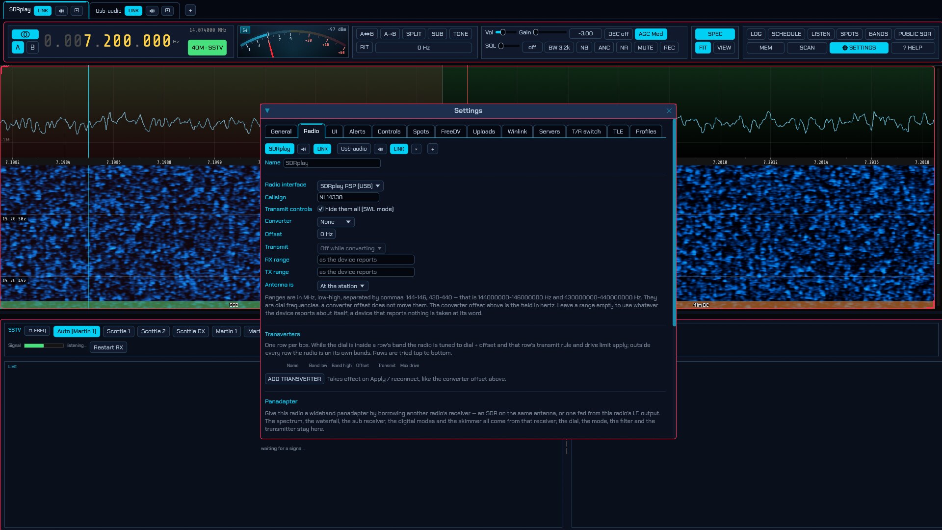
The SDRplay RSP (USB) interface drives any RSP — RSP1, RSP1A, RSP1B, RSP2, RSPduo, RSPdx, RSPdx R2 — natively, with no SoapySDR in the path. Receive only, 1 kHz–2 GHz, up to 10 Msps of complex IQ.
This SDR needs a vendor package. The SDRplay API is required. This is a
userland library plus a background service that owns the hardware. Install it
from sdrplay.com/api (v3.x) and make sure the
service is running — on Linux sudo systemctl enable --now sdrplay; the
Windows and macOS installers start automatically. SDR Oxide finds the library
at runtime, so every build has this backend, and sdroxide --probe tells you
which piece is missing when the device list stays empty: the library, the
service, or the device.
On Linux, an RSP1 needs one more thing. The original RSP1 is a Mirics
MSi2500 and enumerates as USB 1df7:2500, which is exactly what the kernel’s
own in-tree msi2500 driver binds to — so on a stock Ubuntu (or Mint, or
Debian) the kernel claims the receiver before the SDRplay service ever sees it,
and the service reports no device however plainly the RSP is plugged in. The
RSPs after it use other product ids and are not affected, which is why this is
an RSP1 story, and why the same receiver works on a Mac and not here. SDR Oxide
looks for this and names it in the error, and the fix is to keep those drivers
out of the way — put
blacklist sdr_msi3101
blacklist msi001
blacklist msi2500
in /etc/modprobe.d/blacklist.conf, run sudo rmmod msi001 msi2500, then
unplug the receiver and plug it back in.
- Receiver — which RSP to open, by the serial the API reports. Rescan asks the service for its device list; nothing is opened, so it is safe while receiving.
- Sample rate — the effective complex rate. Below 2 Msps the ADC still runs at 2 Msps and the service decimates, which is the normal way to run a narrow span. Above 6.048 Msps the ADC trades resolution for speed (12 bits up to 6.048 Msps, 10 to 8.064, 8 beyond) — worth knowing before picking 10 Msps for weak-signal work. Takes effect on Apply / reconnect. With both RSPduo tuners running the list is shorter, and not by choice: see below.
- IF bandwidth — the tuner’s analog filter. Auto picks the widest one that fits the sample rate, which is what you want unless a strong off-channel neighbour argues otherwise.
- AGC — the RSP’s own hardware IF-gain loop, run by the service at 5, 50 or 100 Hz, with an adjustable set point in dBFS. Off hands the IF gain slider back to you — the setting for measurement and weak-signal digital modes. While a loop runs, the IF slider greys out and the gain readout follows what the loop actually did, not what the slider last said. How low the set point may go depends on the sample rate, because the converter has less headroom to give as it goes faster: −72 dBFS below 8.064 Msps, −60 below 9.216 and −48 above — which over the rates offered here means the full range up to 8 Msps and a −48 floor at 10. The slider follows the rate you have picked, so there is nothing to work out.
- IF gain reduction — the RSP’s native gain unit, and deliberately kept that way so numbers translate directly from SDRuno/SDR++ practice: 20 dB is maximum gain, 59 dB minimum.
- Extended IF range — lets that reduction go below 20 dB, down to 0: the last 20 dB of gain the receiver has, which the API keeps behind a switch of its own and sdroxide leaves off by default. Off is the right setting for ordinary listening, the bottom of the range being where an RSP is easiest to overload; on is for weak signals with the LNA already at state 0. It also lets the AGC set point go up to 0 dBFS.
- LNA state — the front-end attenuation ladder: state 0 is maximum gain, each step switches more attenuation in. How many states exist depends on the model and the band (an RSP1B has ten on VHF but seven on HF), and the slider ends where the band the radio is on ends rather than at the model’s widest. A higher state chosen on another band is kept and still shown beside the rail: the driver clamps to what this band has, keeps your choice, and restores it when you tune somewhere it fits. The default is state 4, not 0: full front-end gain on a real antenna drives the ADC straight into overload, which no amount of IF gain reduction can undo. This is also the control behind the main window’s Gain slider — the IF gain belongs to the hardware AGC whenever a loop is running, the LNA is always yours.
- Frequency correction — reference error in parts per million, applied by the device itself.
- FM broadcast / DAB notch — hardware notch filters over 88–108 MHz and 165–230 MHz, for when a local broadcaster overloads everything else. Models that lack one simply do not show the row.
- Antenna — on the RSP2 (A / B / Hi-Z), RSPdx and RSPdx R2 (A / B / C), and the RSPduo’s tuner 1 (50 Ω / Hi-Z). Applied live; the Hi-Z inputs have a shorter LNA ladder, which the clamping above absorbs.
- Tuner (RSPduo) — which of the two tuners to run, chosen when the device opens. With Run both tuners on (below) this names the tuner this radio listens on: the other one carries the second aerial, or belongs to the second radio. Master/slave operation — sharing the receiver with another application — is not supported.
-
HDR mode (RSPdx / RSPdx R2) — the high-dynamic-range path below 2 MHz, with an HDR filter beside it (200 kHz / 500 kHz / 1.2 MHz / 1.7 MHz) once it is on. It is not a mode that follows the dial: the path’s filter is built only at a fixed handful of centres — 135, 175, 220, 250, 340 and 475 kHz for the two narrow settings, 516, 875, 1125 and 1900 kHz for the two wide ones — and tuned anywhere else it could do nothing.
HDR does not work yet. On the one RSPdx it has been tried against, switching the path on silences the receiver: at every one of those centres, every filter, both antenna ports, LNA states 0–8, levels from −80 to −40 dBm, before
Initand at runtime, at 2.0/1.0/0.5 Msps, zero IF and 450 kHz IF, and every LO setting. The parameter blocks match SDRplay’s own header and SoapySDRPlay3 drives the mode the same way, so whatever it needs is not on the documented API surface. Leave the switch off unless you are the one looking for it; sdroxide says so on screen while it is on. - Bias tee — about 4.7 V DC up the coax for an active antenna (every model except the original RSP1).
The bias tee puts DC on the feedline. The same standing warning as the RTL-SDR applies: never enable it with a transceiver, a DC-grounded antenna, or a preamplifier powered from somewhere else on the other end of the cable.
If the service reports the ADC overloaded, sdroxide shows it on screen and in the log: raise the LNA state, lower the IF gain, or turn the AGC on. If the RSP is unplugged — or the service restarted under sdroxide — it notices within a few seconds and reconnects by itself when the device returns.
The RSPduo’s second tuner
Help wanted — this has not been verified against an RSPduo. Dual-tuner operation here is written from SDRplay’s API rather than measured on the hardware. If it misbehaves, the log is the place to look: it says which tuner is which, whether the two streams are being paired by the service’s sample numbers or by arrival order, and how deep a null the filter is reaching.
An RSPduo is two complete tuners on one board, clocked from one reference. Run both — Run both tuners on the Radio tab — and there are two things worth doing with the other one. Used for picks:
- A second aerial (diversity / QRM suppression) — the two are combined. Because they are clocked together they hear their spans at the same instant, with a relative phase set by the aerials and the feedlines rather than by chance, and that is what makes combining them possible. Same arrangement, and the same adaptive filter, as the LimeSDR’s second receive chain in §6.2.17.
- A second radio, on its own frequency — the two are left apart. The tuners tune separately, so one RSPduo can be an HF radio in one tab and a VHF radio in another; see Both tuners as two radios below.
Either takes effect on Apply: which mode the board runs in is chosen when it is opened.
Diversity and QRM suppression
What to do with it picks between the two jobs:
- Cancel — null a noise source. The DSP form of a noise-cancelling phaser. What the second aerial hears is subtracted from what the first one hears, in the gain, phase and delay that make the two versions of the noise line up, and what is left is the band without it. The second aerial wants to hear the noise and as little of the band as possible — a short whip next to the offending switched-mode supply, a loop pointed at it, or simply the noisier of two aerials.
- Combine — diversity reception. Two aerials on the same signal, added in the phase that makes them reinforce and weighted so the one hearing it better counts for more. On HF the two fade independently, so this fills in the fades: 3 dB on two equal aerials, and much more when one is momentarily in a null.
The rest of the controls:
- Its LNA state and Its IF gain reduction — the second tuner’s own gains, because the two aerials are rarely the same aerial. Set them so both show about the same noise floor: this is the adjustment everything else rests on. Combining weights the two branches by their noise, and a second front end driven into overload hands the filter a distorted copy of the interference, which cannot be subtracted from an undistorted one. A steady gain is also what the filter wants, so switching the AGC off is worth it for a null you mean to keep — the loop owns the IF gain while it runs, on both tuners.
- Filter length — one tap is a gain and a phase, which is a null at one frequency that gets worse either side of it (all an analogue phaser can do). Each further tap buys one sample period of the path difference between the two aerials that the filter can equalise, which is what turns that notch into a band quiet all the way across. The panel says what a given length costs on the sample path.
- Adaptation, Hold and Restart — how fast the filter chases, whether it chases at all, and starting it again. The workflow is: adaptation well to the right, watch the waterfall until the noise drops away, then Hold. A filter left adapting will re-aim itself at whatever becomes loudest, which on a quiet band is the station you are listening to.
Everything except Run both tuners and Used for applies as you change it — finding a null is done by adjusting and listening. Those two reopen the device, because the API fixes the mode when the RSPduo is selected.
The three you use while listening are on the main window. With a filter running, the strip grows a DIV box (a DIV menu on a narrow window): the mode — CANCEL or COMBINE, click to swap — HOLD, RESTART, and the adaptation rail. That is the whole workflow with the waterfall in front of you: adaptation to the right, watch the noise drop away, HOLD. What stays in the settings dialog is what you set once — the filter length, and the second aerial’s own gains. The box appears only while a filter is actually running, so it is also the confirmation that one is.
What running both tuners costs. The API puts the ADC at a fixed 6 MHz and hands back 2 Msps from a low IF, so 2 Msps is the widest span with both running (1.536 MHz of it inside the analog filter), and the narrower rates are that decimated. The sample-rate and bandwidth lists shrink accordingly, and a wider rate left over from single-tuner operation is clamped rather than refused. Both tuners get the same span, the same filter and the same notches — two branches filtered differently are two branches the filter cannot line up — and both follow the dial together.
Nothing here can tell a wanted signal from an unwanted one. The filter only knows what the two aerials have in common, so pointing both at the same thing in Cancel will dutifully cancel the station. How deep a null it is achieving goes to the log every ten seconds — a converged canceller on a real noise source reads 15–30 dB, and one reading a fraction of a decibel is one whose second aerial cannot hear what it is being asked to subtract.
If the second tuner stops delivering, the first one carries on alone and the log says so: the receiver keeps working and the filter stops, rather than the other way round. Asking for both tuners on any other RSP — a setting left behind by an RSPduo — is reported on screen and ignored.
Both tuners as two radios
Set Used for to A second radio, on its own frequency and the pair is not combined at all: each tuner is a receiver of its own, tuned where you like. One RSPduo then serves two radio tabs — HF in one and VHF in the other — from one board and one connection to the API service.
Both radios have to be set up for it, because whichever one opens the board is what puts it into dual-tuner mode:
- On the first radio: pick the RSPduo, tick Run both tuners, set Used for to A second radio, and set This radio’s tuner to the one its aerial is on. Apply.
- Add a second radio (Settings → Radio → +, §2.17), give it the same receiver (the same serial), the other tuner, and the same two settings. Apply.
It does not matter whether the two radios name the board the same way — one picked from the list by serial and the other left on first found are the same receiver, and sdroxide resolves them to it before looking for a session to join (issue #392). A second radio that reports no SDRplay RSP found while the first one is happily receiving is the older behaviour, from before that; if you still see it, the message now says instead that the board is already open here and what to set.
Either order works, and either radio may be started first; the second one to open finds the board already running and takes the tuner that is free. Closing one leaves the other streaming, and the board is only handed back to the service when the last radio lets go.
What the two share, because the hardware does:
- The sample rate. One ADC clock and one decimator setting serve both, so whichever radio opened the board sets the rate and the other adopts it — its own rate setting is remembered but not used while it is the second one in. The dual-tuner ceiling of 2 Msps applies as always.
- The reference trim (Frequency correction), which is the board’s.
- The notch filters and bias tee are not shared: those are per tuner, and each radio drives its own.
Neither radio transmits — no RSP does — and a tuner belongs to one radio at a time: a second radio pointed at a tuner that is already running, or at the second tuner of a board being used for diversity, is told so and does not open.
6.2.9 Airspy HF+ (USB)
Help wanted — this backend has not been verified against real hardware. It was written from Airspy’s own reference implementation rather than on a bench. If it misbehaves, the Radio tab has a Copy diagnostic report button; that report contains every command exchanged with the receiver, the sample-rate and calibration tables it reported, the whole tuning calculation, and the first bytes of the sample stream decoded as I/Q pairs. It is what makes a fix possible.
The Airspy HF+ (USB) interface drives an Airspy HF+ Dual, Discovery
or Ranger directly, using sdroxide’s own USB driver. There is no SoapySDR, no
libusb and no libairspyhf involved, so this works in every build — including the
standard Windows .msi and macOS .dmg — with nothing to install beyond access
to the device itself (see the README’s Airspy HF+ permissions).
Coverage is 0.5 kHz–31 MHz and 60–260 MHz on a Discovery or Ranger, from 9 kHz on a Dual, at up to 912 kSPS of complex baseband. Receive only — there is no transmit path in this hardware.
All three models share one USB id, so the device list cannot tell them apart; sdroxide asks the receiver which it is once the device is open, and the model appears in the interface label at the top of the window.
- Receiver — which one to open, by the serial in its USB descriptor. Rescan re-lists the bus; it opens nothing, so it is safe to press while receiving. Leaving this at first one found is fine with a single receiver.
- Sample rate — which rates exist depends on the model and the firmware, so once a receiver is connected the list shows that receiver’s own rates. Before one is connected it shows every rate any HF+ is known to offer, annotated with who each belongs to. Takes effect on Apply. If the configured rate is not one the hardware has, sdroxide uses the nearest one it does and says so on screen rather than refusing to open.
- AGC and AGC threshold — the receiver’s own gain control. Leave it on for general listening. High threshold trades a little sensitivity for headroom against strong neighbours, which is the right setting on a crowded band at night. Turn the AGC off to set the attenuator by hand for measurement.
- Attenuator — front-end attenuation expressed as a gain, so 0 dB is none and the slider goes down from there. The step comes from the receiver’s own table (six dB on every firmware seen so far). Only obeyed with the AGC off.
- Preamp (LNA) — the HF low-noise amplifier. It buys sensitivity at the cost of intermodulation, so it is off by default, which is usually right on a real antenna.
- Frequency calibration — in parts per billion, this receiver’s own unit and a thousand times finer than the ppm an RTL-SDR uses. Leave Use the receiver’s stored value ticked and the figure Airspy’s own tool wrote into the receiver’s flash is used. Untick it to override for the session. Nothing here is ever written to the receiver’s flash — that page also holds the oscillator trim, and a wrong write would cost the receiver its factory calibration.
- Bias tee — DC up the antenna coax. Not every HF+ has one; on a receiver without, this does nothing.
- Host DSP — the image balancer, the zero-IF offset and the fine-tuning oscillator, all three together. See below.
The bias tee puts DC on the feedline. The same standing warning as the RTL-SDR applies: never enable it with a transceiver, a DC-grounded antenna, or a preamplifier powered from somewhere else on the other end of the cable.
What the host does. The receiver’s firmware does the filtering; sdroxide does what the vendor library does, and for the same reasons:
- An adaptive IQ image balancer on the zero-IF rates (768 and 912 kSPS), where quadrature imbalance in the hardware would otherwise leave a mirror image of every signal reflected about the centre of the passband. It converges over several seconds of real signal and re-converges after a retune, because the imbalance is frequency-dependent. The low-IF rates do not need it and do not run it.
- DC cancellation, so the converter’s own offset does not sit as a spike in the middle of the panadapter.
- A fine-tuning oscillator. This one is not a nicety. The synthesiser is programmed in whole kilohertz, so the oscillator carries the rest of the dial; on a zero-IF rate the synthesiser is deliberately parked 5 kHz off so its own leakage stays clear of your signal, and the oscillator brings the signal back; and below the synthesiser’s floor — 180 kHz on a zero-IF rate, 84 kHz on a low-IF one — the oscillator does all the tuning. That last part is how this receiver reaches VLF at all.
Untick Host DSP to see raw hardware output. With it off, the mirror image appears on the zero-IF rates, DC is no longer removed, and the dial is accurate only to the nearest kilohertz. It is also the quickest way to tell a driver problem from a DSP one: if something looks wrong and turning this off changes it, the DSP is where to look.
If the receiver is unplugged, sdroxide notices within a few seconds and reconnects by itself when you plug it back in — no need to press Apply.
6.2.10 Icom LAN (network radios)
The Icom LAN (network) interface drives an Icom over the Ethernet or WiFi port on the radio itself, using the same IP-remote protocol Icom’s own RS-BA1 software speaks. No licence for RS-BA1 is needed, and no computer at the radio end: sdroxide talks to the transceiver directly.
It covers every Icom with a network port — the IC-7300MK2, IC-705, IC-7610, IC-7760, IC-7851/IC-7850, IC-9700, IC-905 and IC-R8600 — because the protocol is the same on all of them and the radio reports its own CI-V address when the session opens. There is nothing to choose from a model list. On the two-box IC-7760 it is the [LAN] port on the RF deck that speaks this protocol, not the one on the controller.
One connection carries three things:
- Control — the whole CI-V command set, tunnelled over the network. Dial,
mode, PTT, the S-meter, SWR, the antenna selector (
ANT1/ANT2, on a radio that has one), the radio’s own CW keyer, and its power switch — the radio can be switched off and on again from here, since its network module stays awake while the set is off. - Audio, both ways, at up to 48 kHz.
- The radio’s spectrum scope — its own sweep, 475 points on most models and 689 on an IC-7610 or IC-7760, up to ±500 kHz wide. On the AF path this is the main panadapter; on the 12 kHz IF it is the full-band waterfall above it.
On the radio, first
Three settings, all under MENU » SET:
- Network > Network Control — ON. Without it the radio never answers.
- Network > Network User1 (or User2) — set a network user name and password, and enter the same pair in sdroxide.
-
Connectors > MOD Input > DATA OFF MOD and DATA MOD — LAN (on an IC-705, WLAN), or transmit audio is not heard. An IC-7610, IC-7760 or IC-7851 has three data slots rather than one, DATA1 MOD through DATA3 MOD, and all of them want LAN. sdroxide writes this for you on a model whose menu numbering it knows — every transceiver in the list above — and on any other it says so in the status line and leaves the menu alone. Not on a receiver: an IC-R8600 has no modulation input to set, so neither the write nor the warning appears.
It is a loan, not a keep: sdroxide reads what these items hold before it writes anything, and puts them back the way it found them when the session ends — the radio switched off in sdroxide, its tab closed, the interface changed, or the program quit. A rig left on LAN is deaf to its own microphone and its own key the next time it is used on its own in the shack, with nothing on the radio saying why (issue #252). The same goes for the LAN AF/IF Output > Output Select item sdroxide sets for the 12 kHz IF. Two things it cannot put back: an item the radio never answered a read for, and a session that ends because the link died — a radio unplugged or a WiFi that went away keeps whatever it had at that moment.
On an IC-7851/IC-7850 the first two live under SET » OTHERS rather than a Network submenu, and the third is CONNECTORS » DATA OFF MOD with
LANat the end of a nine-entry list. Same three settings, different signposting.The numbering is what sdroxide has to know, and it is not the menu path: it is a flat index the manufacturer renumbers between models, with the radio’s calibration marker a few places away from the modulation block. That is why an unrecognised model is asked to set the item by hand rather than guessed at. A radio whose CI-V address you have changed in Connectors > CI-V is still recognised: the name it reports is matched too, and either piece of evidence on its own is enough. Only when the two name different Icoms — a network radio name typed over the model’s — does sdroxide fall back to the address alone.
A receiver in the IC-R line gets no PTT, drive, tune or SWR controls at all, whatever its capability block says — at least one of them advertises a transmit stream over this protocol on a set with no transmitter in it.
Note the radio’s IP address from its Network screen — an Icom does not announce itself on the network, so there is no Discover button.
A tune over a network
A frequency sent over this link is a UDP datagram, and the radio never says it acted on one. So sdroxide watches for the radio to report the new frequency back, and if it has not within a fraction of a second it sends the tune again — up to a second, after which the radio has the last word. Over the same second the one frequency it will not accept from the radio is the one you just tuned away from: the answer to a question asked before the tune can arrive late, and out of order, and adopting it puts you back on the band you just left. That was a band change in FT8 taking three to five clicks (issues #285 and #297).
None of this overrules the radio. Turn its own dial and sdroxide follows at once, and a frequency the radio will not go to — outside its range, or a lock switch — wins after that second rather than being argued with.
How wide the waterfall gets
No Icom outputs I/Q over the network. One outputs it at all: the IC-7760’s RF deck has a USB 3.0 socket that streams 1.92 Msps I/Q, but only through a manufacturer-supplied FTDI driver on Windows, and nothing of it reaches the [LAN] port beside it. So over the network the ceiling is the same on every model, for sdroxide and RS-BA1 alike:
- On AF the radio has already demodulated, so the audio stream is not a picture of the band at all — it is a picture of what came through the rig’s filter, one-sided and never wider than that filter. The panadapter is therefore the radio’s own scope: centred on the dial, as wide as Scope span, and the same view SDR-Control and RS-BA1 give. It is a picture the radio draws and sends as finished magnitude bins — 475 of them, or 689 on an IC-7610 or IC-7760 — so clicking it tunes but nothing can be demodulated, notched or skimmed inside it without moving the dial.
- On the 12 kHz IF the panadapter is real spectrum — about ±12 kHz around the dial at 48000 Hz — which can be demodulated, notched, decoded and skimmed. The scope then lives in the strip above it instead.
- Zoom in past the rig’s filter and the audio takes over. The scope is 475 points across whatever Scope span is set to — 1053 Hz per point at ±250 kHz, 105 Hz at ±25 kHz, and about a third finer than that on an IC-7610’s or IC-7760’s 689 — and it arrives about four times a second whatever the span, so past a point zooming magnifies rather than resolves and a signal stays one block wide. Once the visible window fits inside the rig’s passband the panadapter is drawn from the demodulated audio instead: 48 kHz through the panadapter’s own transform is a few hertz per bin, arriving twenty times a second, and the waterfall gets a proper row for every one of them. Zooming back out hands the picture to the scope again — the frequency axis stays the scope’s either way, so nothing jumps.
- The digital modes always get the audio band, on either path. FT8 and the keyboard modes place stations by their offset inside the rig’s passband, and a band-wide sweep at a few hundred Hz per bin cannot show one, so the panadapter switches back to the audio spectrum for as long as such a mode is selected.
- The full-band waterfall — the strip above the panadapter, switched on with the WIDE button in the Display module — carries the scope on both paths, up to 1 MHz across. On AF that is worth leaving on once you zoom the panadapter into part of the sweep, since the strip keeps the whole of it.
Because the scope is uncalibrated — Icom publishes a 0..160 amplitude scale (0..200 on an IC-7610 or IC-7760) with no dB per step — its levels are ranged automatically rather than from the FIT / floor-and-ceiling controls, which govern the audio-band panadapter and every other front end as before.
The strip appears on its own once the first sweep arrives, and the WIDE button
appears with it. If neither ever shows up, the radio is not sending its scope:
Copy diagnostic report and look at the scope sweeps counter — zero against
a healthy CI-V frames in count means the 27 10/27 11 writes did not take.
A scope that stops in the middle of a session restarts itself. Nothing on this link reports that the sweeps have stopped, and several ordinary things stop them — an enable lost on the way (these are single UDP datagrams that nothing re-sends), the radio’s own scope screen being closed and reopened, or the CI-V stream reconnecting under a session that otherwise carries on. sdroxide notices the silence after about three seconds and sends the enables again, backing off while the scope stays quiet, so the strip comes back without a reconnect. The watchdog holds off while you transmit, since a radio that stops sweeping for the length of an over is behaving normally. The log and the wire trace record each stall and recovery.
The flip side is that switching the scope off on the radio will not stick while the strip is on — the watchdog reads it as a fault and turns it back on. Clear Show the radio’s spectrum scope in the connection settings instead.
If the strip is there but barely wider than the panadapter, the span is the reason: the radio sweeps whatever span was last chosen on its own screen, and that is often a few kHz. Scope span sets it from here.
- As set on the radio leaves it alone — for an operator who is also watching the radio’s own display.
- Any other value is commanded when the session opens, and also puts the scope into centre mode so it follows the dial. It changes the radio’s own screen too, which is the price of the wider view.
The default is 200 kHz (±100k), about 400 Hz per bin — a whole HF sub-band at once. ±500k gives a megahertz at 2 kHz a bin. A radio that does not offer a particular span refuses it and keeps the one it had.
Receive from: AF or the 12 kHz IF
Receive from is the one setting worth thinking about. It selects what the
radio puts in the audio stream (SET > Connectors > LAN AF/IF Output > Output
Select), which decides who does the demodulating:
- AF — the radio demodulates. The radio’s filters, AGC and detector do the work, and the panadapter is the radio’s own scope — see above. This is the safe default and works on every model at every sample rate.
-
12 kHz IF — sdroxide demodulates. The radio sends its DRM intermediate frequency instead of audio. sdroxide mixes it down to baseband and treats it as an ordinary receiver front end, so its own filters, noise reduction, notches, digital-mode decoders and skimmer all apply — over roughly ±12 kHz around the dial.
This needs the 48000 Hz audio rate; at anything lower there is no room for a 12 kHz IF and sdroxide falls back to AF and says so. How much of that ±12 kHz is genuinely usable is not documented by Icom and has not been measured here, so treat the width as approximate.
Transmit is unaffected by the choice: it is always audio the radio modulates.
IF spectrum: which way round the IF runs
Only on the 12 kHz IF, and only worth touching if something is wrong.
A 12 kHz IF is a real signal, so it carries the band you want and a mirror of it, and sdroxide has to pick one. Pick the wrong one and everything still sounds like a radio — it is just mirrored, which on SSB means the audio comes out on the opposite sideband to the one it was sent on. The giveaway is having to select USB on 40 m and LSB on 20 m to make anybody intelligible, with the radio’s own mode display agreeing with sdroxide the whole time.
- Automatic (the default) uses what the model is known to do: mirrored on an IC-7760, normal on every other Icom.
- Normal and Mirrored set it by hand.
Icom documents this nowhere — not in the CI-V reference guides, not in the IC-7760’s I/Q supplement — so the automatic answer is built from what radios have actually been reported to do, and the IC-7760’s comes from a single operator’s session. If your radio needs the opposite of what it is given, set it by hand and please say so, so the default can be corrected. The IC-7610 is the one to watch: it shares the IC-7760’s scope shape and may well share this too, but nobody has reported it, so it is left alone.
The dial and the mode belong to the radio
Both travel in both directions, on either receive path. Turn the radio’s dial or change its mode and sdroxide follows within a fifth of a second; change VFO or mode in sdroxide and the radio follows. On the 12 kHz IF the mode still matters even though sdroxide is the one demodulating — it is the mode the radio will transmit in, and the radio’s own display should not disagree with yours. What it will not fix is a mirrored IF: the sideband you hear on that path is sdroxide’s to choose, not the radio’s, which is why a swap there is the IF spectrum setting above and not this one.
What sdroxide will not do is impose the session’s dial or mode when the connection opens: it adopts whatever the transceiver is already sitting on. Starting a session by retuning somebody’s radio out of a config file is not what a transceiver operator expects — unlike an SDR dongle, this radio was somewhere deliberate before you connected.
If the radio refuses a mode it does not have, it keeps the one it was in and sdroxide follows it back after about a second.
The rest of the tab
- Radio address and Control port — the address from the radio’s Network screen; the port is 50001 unless it has been changed there.
- Network user and Password — as set on the radio. The password is
stored in the clear in
radio.json; the protocol obfuscates it reversibly on the wire, so keeping it secret here would protect nothing. - Audio sample rate — 8000, 16000, 24000 or 48000 Hz.
- Displayed bandwidth (AF only) — the width of the audio-band panadapter.
- CW keying — as for a CAT rig. A radio in CW ignores the audio it is sent and keys its own transmitter, so Rig keyer (CAT) is what puts CW on the air at the dial frequency; Sound card (MCW) sends the keyed tone as audio instead and keeps the radio in plain USB — the same mode the digital modes ride here (§6.2.2).
- Transmit buffer — how much audio the radio holds before modulating. More survives a worse network, at the cost of transmit latency.
- Show the radio’s spectrum scope — stream the sweep into the full-band waterfall.
- Scope span — how wide to sweep it; see above.
- Switch modulation input to LAN — do step 3 above automatically, where the model is known, and put the radio’s own setting back when the session ends.
- Test connection — connect, report what the radio said it is, and disconnect.
- Copy diagnostic report — the last session’s handshake and CI-V trace, as text. It is this radio’s session: with two Icoms on the LAN, each tab’s button answers about the address that tab is configured for, and a radio nothing has connected to yet says so rather than handing over the other one’s conversation.
6.2.11 RTL-SDR over rtl_tcp (network dongles)
The RTL-SDR over rtl_tcp (network) interface is the dongle from
§6.2.5 on a different machine — typically a
Raspberry Pi at the foot of the mast, so the coax run is a metre instead of
thirty. The far end runs rtl_tcp, which owns the dongle and performs every
register write on sdroxide’s behalf; this end sends five-byte commands and
receives the same 8-bit I/Q the USB endpoint would have produced.
On the remote machine:
rtl_tcp -a 0.0.0.0
The -a 0.0.0.0 matters. With no -a, rtl_tcp binds to localhost and only
accepts connections from the machine it is running on. Add -p if you want a
port other than 1234, and -d to pick between several dongles. Any server that
speaks the protocol works — osmocom’s rtl_tcp, the rtl-sdr-blog fork’s, or one
of the several re-implementations.
The settings are deliberately the same ones as the USB tab, in the same order, because it is the same radio; only these differ:
- Server address —
hostorhost:port. The port defaults to 1234. A hostname, an IPv4 address or a bracketed IPv6 literal all work. Takes effect on Apply. - Sample rate — shown with what it costs on the link, because that is the
number that decides here. The samples are sent uncompressed at two bytes per
complex sample: 1.024 Msps is 16 Mbit/s, 2.4 Msps is 38 Mbit/s. The default is
1.024 Msps rather than the USB tab’s 2.4, since it has to fit down a network.
A rate the link cannot carry does not degrade gracefully —
rtl_tcpdrops a client that stops keeping up, and sdroxide then reconnects, so the symptom is a stream that restarts every few seconds rather than one that gets choppy. Wired Ethernet carries any rate on the list; a single WiFi hop is usually good for 1.8 Msps and reliable at 1.024. -
Frequency correction — the crystal error of the remote dongle. It is a property of that hardware, so it is set here and not in the USB tab.
The measured clock-error line that the USB interface prints (§6.2.5) is not available over
rtl_tcp, and the log says so instead of printing a figure. That measurement counts samples against elapsed time, which works because the dongle itself paces them; over a network it measures the buffering in between. Against a realrtl_tcpon loopback — the best case there is — successive readings 25 seconds in ranged from -770 to +2600 ppm for a dongle whose real error is a few. Calibrate the dongle on USB once and carry the number across, or tune a broadcast station of known frequency and adjust until it sits on the dial. - HF reception — with one wrinkle the USB tab does not have. The protocol reports the tuner chip and nothing else, and a Blog V4 is an R828D like any other R828D, so sdroxide cannot tell them apart over the wire. Automatic therefore leaves an R828D alone — right for a V4, which upconverts inside the server’s own tuning call — and switches anything else to direct sampling below 24 MHz. If your remote dongle is a plain R828D that hears nothing on HF, choose Direct sampling (Q branch) explicitly; that is always obeyed. The second-Nyquist note above applies at the far end just the same.
- Bias tee — feeds the coax at the far end, which may be out of sight and up a mast. sdroxide turns it off when the connection closes cleanly, and warns while it is on. Older servers do not implement the command at all; because the protocol has no replies, a bias tee that fails to come on cannot be distinguished from one that did.
Everything else — AGC, tuner gain, IQ correction — behaves as on the USB tab and applies as you change it, without reconnecting.
Two consequences of the protocol are worth knowing, because they look like bugs and are not:
- Nothing is ever reported back. There are no replies in either direction: the gain slider shows what was asked for, not what the far end’s tuner snapped it to, and the sample rate is the requested one. Over USB sdroxide reads both back from the hardware.
- The dongle is not selectable from here.
rtl_tcpchose its dongle when it started, with-d. There is no serial, no product string and no device list in the protocol, so there is nothing to rescan.
A dropped connection is retried on its own: a server that is restarted, a Pi that reboots, or a client dropped for falling behind all come back without touching anything on the Radio tab.
SDRplay servers (rsp_tcp)
rsp_tcp publishes an SDRplay RSP over the same protocol, and sdroxide connects
to one through this interface — not the SDRplay one, which drives an RSP on
this machine through the vendor API.
There is a wrinkle worth knowing, because it is not what anyone expects. An
rsp_tcp server greets exactly like a dongle: magic "RTL0", tuner type
R820T. It poses as an RTL-SDR so that every existing rtl_tcp client keeps
working. The "RSP0" marker that looks like it ought to be the greeting belongs
instead to a 45-byte capability block that the server sends after the
greeting, and only when it was started with -E.
So run the server with -E if you can. With it:
- sdroxide names the radio properly on the Device tab — hardware version, antenna inputs, tuner count, IF gain-reduction range and which filters it has — instead of repeating the R820T the server is pretending to be;
- 16-bit samples work. A server started with
-b 16streams signed 16-bit instead of 8-bit, and there is no way to discover that outside extended mode: the protocol carries no such field. Without-E, a-b 16server’s stream is read as 8-bit and looks like noise. This is a real trap and the reason to prefer-E; an RSP’s ADC is 14-bit, so 8-bit throws away most of what makes the receiver worth having.
The SDRplay server group on this tab sends the RSP-specific commands —
antenna input, LNA state, IF gain reduction, the RSP’s own AGC and set point,
the notch filters, and the reference clock output. They are shown always rather
than when a server is detected, because there is nothing to detect against a
server without -E. An ordinary rtl_tcp server ignores them: this protocol
has no replies and silently discards commands it does not recognise, which is
the same reason a bias tee that does not come on is not necessarily this end’s
fault.
The gain controls above the group are the dongle ones and do nothing on an RSP. Use LNA state and IF gain reduction instead — and note that IF gain reduction is a reduction, so a bigger number is less signal.
rtl_tcp has no authentication and no encryption. Anyone who can reach the port gets the dongle and can retune it — including turning its bias tee on. Keep it on a network you trust, or reach it through a VPN or an SSH tunnel (
ssh -L 1234:localhost:1234 pi@host, then connect to127.0.0.1:1234here, leavingrtl_tcpbound to localhost on the far end).
6.2.12 HackRF One / Pro (USB)
A HackRF One or HackRF Pro — or a Jawbreaker or a rad1o — driven directly over USB by sdroxide’s own pure-Rust driver. No SoapySDR, no libusb and no libhackrf, so this interface is in every build variant on every platform. DC to 7.25 GHz, 2 to 20 Msps, wideband IQ in both directions; a Pro takes narrower rates, down to 250 ksps.
This is the only USB interface here that transmits, and the only one that is half duplex: receive stops for the length of every over, because the hardware has one signal path and switches it. Nothing you can configure changes that.
Permissions. Linux needs the packaged udev rule — see “HackRF permissions” in the README. Windows normally needs nothing: a HackRF carries the Microsoft OS descriptors that ask for WinUSB by itself. macOS needs nothing.
Radio. Rescan lists what is on the bus. The serial is matched on its suffix, which is why the list shows only the last eight digits: a HackRF serial is 32 hex characters of which the leading half is zeroes on every unit, and nobody types the whole thing. Leave it empty for “the first one found”.
A HackRF Pro appears in this list as “HackRF Pro” and is otherwise the same
radio to drive: it carries the HackRF One’s USB id, answers the same vendor
requests, and streams the same 8-bit I/Q. Three things about it are different
and sdroxide reads all three off the board rather than assuming — see the notes
on sample rate, tuning range and baseband filter below. Its half-precision
(4-bit, 40 Msps) and extended-precision (16-bit) gateware modes are not
driven here; if some other program has loaded one with hackrf_debug -P, the
radio stays in it until you unplug it and sdroxide will show noise.
Sample rate. 2 Msps is the default and the gentlest on the host. Everything below 8 Msps is outside the MAX5864’s specified range — it is what everyone uses regardless, and it is the rate the LO-offset behaviour was measured at, so it is offered with a note rather than hidden. 20 Msps is 40 MB/s, which is what the High-Speed USB 2.0 link every HackRF has is rated for; there is no SuperSpeed HackRF to move it to, and sdroxide only says something about the link if the board has enumerated below high speed — a cable or hub problem, and one no sample rate will survive. Changing the rate reopens the radio.
A HackRF Pro is offered four extra rates below that — 250 and 500 ksps, 1 and 1.5 Msps — and only a Pro, because only a Pro can use them. On the other boards a low rate just runs the converter slowly while the narrowest analog filter is still 1.75 MHz wide, so most of what you get back is the rest of the band folded in. The Pro runs its front end fast and decimates in its FPGA, so its narrow rates are narrow all the way through — and at 500 ksps it is sending 1 MB/s over USB instead of 4, with the whole panadapter-and-decoder chain running on a fortieth of the samples.
Gains. The radio’s own model, three stages and a switch:
| Control | Range | Note |
|---|---|---|
| LNA | 0–40 dB, 8 dB steps | Front end. The stage that changes sensitivity, and the stage that overloads first on a real antenna. |
| VGA | 0–62 dB, 2 dB steps | Baseband, after the mixer. Reach for this before the LNA on a weak signal. |
| TX VGA | 0–47 dB, 1 dB steps | Transmit driver. Only shown once transmit is enabled. |
| RF amp | 14 dB, on/off | One switch, offered as two settings — see below. |
The hardware truncates rather than rounds: ask the LNA for 15 dB and you get
- The slider shows back what the radio really did, so it will move under your hand at the boundaries. That is the radio being honest, not the UI fighting you.
The RF amplifier is one switch with two settings. There is a single 14 dB amplifier in the signal path, and it sits in both directions. sdroxide gives you a receive setting and a transmit setting for it and applies whichever belongs to the direction the radio is entering — so you can run the preamp bypassed on receive, where a HackRF front end overloads easily on a real antenna, and in circuit on transmit for the extra output. This works because sdroxide reprograms the entire front end on every change of direction. Reaching the same radio through SoapySDR cannot express it at all: there the receive amp goes dead after the first over and the transmit amp never engages.
Baseband filter. Leave it on Automatic. The filter is coupled to something invisible: sdroxide parks the local oscillator a quarter of the span above your dial so the radio’s own DC spike lands clear of the signal, and it withdraws that offset when the filter is too narrow to reach where the signal was moved to. So a filter chosen by hand and set too low does not merely soften the band edges — it silently turns off the DC-spike avoidance, which looks exactly like the offset being broken. Automatic picks 0.75 × the sample rate, which always leaves room.
On a HackRF Pro this control is greyed out, because that board chooses the filter itself and discards what the host asks for. Its analog chain is nothing like a HackRF One’s — the narrowest setting its transceiver offers is around 10 MHz wide, and everything below that is a switched filter plus decimation that only the radio’s own firmware knows how to combine — so it derives the same 0.75 × sample rate itself and applies it across the whole chain. sdroxide does not send the request at all on that board rather than send one that would be accepted and ignored; if you have a filter pinned from another radio, the status line at open says so.
Tuning range. DC to 7.25 GHz, the same on every board, because that is what the firmware accepts — it clamps a tuning request into 0–7250 MHz and has no per-board table. libhackrf documents the same span and SoapySDR publishes it, which is why a HackRF driven through SoapySDR has always tuned wider here than one driven natively.
That is a wider span than any of these boards is specified for. A HackRF One is a 1 MHz – 6 GHz radio, a Pro is 100 kHz – 6 GHz, and outside those the receiver is heavily attenuated and the transmitter makes little or no power. But attenuated is not the same as absent: people listen to shortwave below 1 MHz on a HackRF, and 5 GHz Wi-Fi is visible above 6, so sdroxide lets the dial go there and lets you judge what you hear rather than deciding in advance that you cannot. Expect a deaf radio at the edges, and do not expect to transmit usefully there.
IQ correction. On by default. This is a zero-IF radio: its own oscillator leakage sits at the centre of the span, and the mixer’s quadrature error puts a mirror image across it. The correction removes both, adaptively. Turning it off shows raw hardware output, which is the quick way to tell a driver problem from a DSP one.
Bias tee. About 3 V at 50 mA on the antenna port, for an active antenna or a preamp. A HackRF One or Pro only — the Jawbreaker and the rad1o have no such circuit, and on those sdroxide does not send the command at all and says so rather than leaving a switch that quietly does nothing. A board that refuses the command anyway — the firmware answers it with a stall on anything that is not a One, an r9 or a Pro, and some boards do not identify themselves as any of those — is a radio with no antenna-port power, not a radio that will not open.
Transmit
Off by default, behind an Enable transmit switch, and the default is deliberate. A HackRF is a wideband transmitter with poor harmonic suppression: it wants an external low-pass filter for whatever band you are on, and it will happily radiate outside it. Somebody who plugged one in to listen should not be one PTT away from that. While the switch is off, sdroxide publishes no transmit channel at all, so nothing anywhere in the program can key the radio.
With it on:
- Into a dummy load until you have measured it. Check the harmonics and the carrier leakage on a second receiver or an analyser before connecting an antenna.
- Drive is applied digitally, before the transmit VGA. Leave the drive high and set your output level with the TX VGA slider — turning drive down instead runs the DAC at a fraction of full scale, which raises intermodulation and the carrier leakage relative to your signal by the same amount you turned it down.
- The carrier sits on your signal. sdroxide’s transmit chain centres the signal at DC and tunes the radio straight to it, so the oscillator’s own leakage lands on the carrier frequency rather than off to one side. This is inherent to the current transmit path, not a setting.
- Receive stops. Half duplex. The panadapter freezes for the length of the over and resumes afterwards, and sdroxide throws away what was buffered when the receiver stopped — those samples are from before you keyed up.
Transmit has not yet been measured against hardware. Receive has. If anything about an over looks wrong, the Radio tab’s Copy diagnostic report button records every command exchanged with the radio in order, including the exact sequence around each key-down — which is the part a bug report needs and the part nobody can reconstruct from a spectrum.
6.2.13 Airspy R2 / Mini (USB)
An Airspy R2 or Airspy Mini, driven directly over USB by sdroxide’s own pure-Rust driver. No SoapySDR, no libusb and no libairspy, so this interface is in every build variant on every platform. 24 MHz to 1800 MHz, receive only.
This is not the Airspy HF+. Same vendor, different receiver: different silicon, a different USB id, a different protocol and a different tuning range. They have separate interfaces, separate drivers and separate udev rules, and neither substitutes for the other.
Permissions. Linux needs the packaged udev rule — see “Airspy R2 / Mini permissions” in the README, and note it is a different file from the HF+’s. Windows wants WinUSB via Zadig or Airspy’s own package. macOS needs nothing.
Receiver. Rescan lists what is on the bus. An R2 and a Mini share the USB
id 1d50:60a1 and the same product string, so the list cannot say which is
which — only the sample rates separate them, and those need the device open.
The serial is matched on its suffix, so the last eight digits are enough.
Sample rate. The rate you pick is the rate you get: an R2 offers 10 and 2.5 Msps, a Mini 6 and 3. Once a receiver is connected the combo shows its rates; before that it shows both models’ and says which is which.
Underneath, the receiver runs at twice the rate shown. Its ADC is real rather than complex — it digitises a real signal at the full rate — and sdroxide makes complex baseband from it on the host with a quarter-rate translate and a half-band decimator. Two consequences are worth knowing:
- The receiver’s own DC offset lands at the edge of the span rather than at its centre, which is the opposite of every zero-IF receiver here. That is why the DC-removal switch below exists and why it is on by default.
- Image rejection is not uniform across the span. A half-band cannot brick-wall, so the inner 80 % of the span gets the full rejection and the outer edges progressively less — at 10 Msps that is the middle ±4 MHz of ±5 MHz. Every receiver built this way makes the same trade, Airspy’s own software included.
Changing the rate reopens the receiver: the rate moves the tuner’s IF and the clock dividers together, so it cannot be changed under a running stream.
Gain is a step along a curve, not three sliders. The R820T2 has an LNA, a mixer and a VGA, and setting them independently is a good way to build a receiver that either overloads or hisses. Airspy publishes two curated curves through the three stages and sdroxide offers the same choice, because that is what the numbers were tuned for and what every other Airspy program does:
| Curve | Use |
|---|---|
| Linearity | Least intermodulation for a given sensitivity. The right default on an antenna with broadcast stations nearby. |
| Sensitivity | More gain for weak signals, less overload margin. |
The Gain slider is a step from 0 (quiet) to 21 along whichever curve is selected. It is not a dB figure — how much a step is worth depends on the curve and the band.
Tuner AGC. The tuner has its own loops for the LNA and the mixer. They are off by default, and for a reason: with one running, the gain slider no longer sets the stage that loop owns — the loop overwrites it a moment later. Use one or the other, not both.
12-bit packing. On by default, and worth leaving on. The receiver can pack its 12-bit samples three-to-a-word instead of padding each to 16 bits, which is a third less USB traffic — and this is a USB 2.0 device carrying up to 30 MB/s packed against 40 unpacked. Firmware too old to have the request streams unpacked and sdroxide says so. Applies on reconnect, because it changes how every transfer is decoded.
Bias tee. DC on the antenna port for an active antenna or preamp. Off by default.
DC removal. On by default. Turn it off to see raw hardware output, which is the quick way to tell a driver problem from a DSP one — but see above for where the spur goes when you do.
Not yet verified against real hardware. If it misbehaves, the Radio tab’s Copy diagnostic report button records every command exchanged with the receiver, the sample-rate arithmetic (which is where a span that is half or double what it should be would show), and the first samples both as raw 12-bit values and decoded as I/Q pairs.
6.2.14 SpyServer (network receivers)
SpyServer is Airspy’s own network server. It works with Airspy R2/Mini, Airspy HF+, or RTL-SDR. Receive only.
There are two interfaces in the picker, and the choice between them is about the link rather than about the radio:
- SpyServer (network) asks for wideband I/Q, exactly as a local SDR delivers it. This is designed for use via LAN.
- SpyServer VFO+FFT, low bandwidth (network) asks for a narrow I/Q window that follows the dial, plus the server’s own FFT of the whole band. Designed for use on slower WiFi, on a cellular modem, or other bandwidth-limited links.
They are separate entries with separate settings, because an operator with both usually has two different servers — one at the mast and one far away — and because a decimation stage that suits a wideband stream is nowhere near one that suits a narrow one.
Everything below applies to both unless it says otherwise.
Server address — host or host:port. The port defaults to 5555, which is
what spyserver listens on unless its config file says otherwise. A hostname,
an IPv4 address or a bracketed IPv6 literal all work. Takes effect on Apply.
On the far end, check that spyserver.config binds an address other machines
can reach. Bound to 127.0.0.1 it accepts connections only from the machine it
is running on.
Two other keys in that file are worth knowing about before you start it:
list_in_directorydefaults to1, which publishes your receiver — with the owner name, antenna description and antenna location you filled in — to Airspy’s public directory for anyone to connect to. Set it to0unless being listed is what you want.allow_controldecides whether a client may retune the receiver and change its gain. With it off, or with another client already holding control, sdroxide is limited to the slice that client is receiving — see below.
Test connection connects, reads what the server says about itself, and
disconnects again without starting a stream, so it is safe to press against a
server somebody else is using. This is worth doing before Apply, because unlike
rtl_tcp this protocol answers: the reply names the receiver on the far end,
the range of rates it offers, and whether this end would be allowed to tune it.
I/Q bandwidth is a decimation stage, not a figure in hertz. Every receiver has a different ladder — its maximum rate halved stage by stage from whatever floor the server sets — and none of it is known until a connection is open, which may be from a machine on the other side of the world from this screen. Storing the stage means the same setting still means something sensible when it is pointed at a different server, and it is what the protocol carries.
Automatic is the default and is usually right. It aims at about 1 Msps on the wideband interface, and about 96 kHz on the VFO one — enough for every mode here including wide FM, at roughly 1.5 Mbit/s at 8 bits. Press Test connection to see what the stages come to on the server you are pointed at. Takes effect on Apply.
Measured against spyserver on an RTL-SDR at 2.048 Msps, the two interfaces
came out at 8.4 Mbit/s and 1.3 Mbit/s for the same band coverage — the wideband
one carrying 512 kHz of I/Q, the VFO one carrying 64 kHz of I/Q plus the whole
1.7 MHz as an FFT. On an Airspy at 10 Msps the gap is far wider.
Sample format decides what a rate costs on the link: 16-bit is twice 8-bit, and 32-bit float is four times it for no more information than the receiver’s ADC had. 8-bit is what makes a remote receiver work over a domestic uplink and is right for almost everything; 16-bit is worth it on an Airspy HF+ over a wired link, where there is real dynamic range to keep. A server configured to insist on one format overrides this and says so in the log. Takes effect on Apply.
Gain is the server’s gain stage, as an index — not a number of decibels. What each index is worth belongs to the receiver on the far end and changes with the band, and the protocol never says, so nothing here can turn it into dB without inventing a figure. The real range is the server’s; an index past it is clamped. Applies immediately.
Digital gain is how far the server scales its samples up before quantising them for the wire. Automatic computes it the way every other client does — from the receiver type, the gain index and the decimation stage — and is almost always right. It matters most at 8 bits: a signal sitting far below full scale loses its lower bits to the quantiser, and this is what puts them back. An Airspy HF+ behind an 8-bit server gets 32 dB of it before anything else, because its analog dynamic range leaves its I/Q a long way down the scale.
Full-band strip asks the server for a low-rate FFT of the whole band as well as the I/Q, and draws it in the strip above the panadapter (the WIDE button in the Display module shows and hides it). It costs almost nothing — a couple of kilobytes a frame, a dozen or so times a second — and it shows the whole receiver rather than the slice being demodulated. Clicking anywhere in it tunes there.
In the VFO interface this is the only band view there is, because the panadapter itself is only as wide as the I/Q being received. Switching it off leaves a receiver with no way to see anything it is not already tuned to.
The band view holds still while the dial roams inside it, and re-centres only when you reach its outer third. That is deliberate: a band picture that slid on every retune would be one nobody could steer by.
The dropdown beside it is how much of the receiver the strip covers. Whole band is the widest view there is; narrowing it puts the same number of bins across less spectrum, which is finer detail over a smaller stretch.
Note that “whole band” is the receiver’s analog bandwidth, which is not its sample rate and is often noticeably less: an RTL-SDR running at 2.048 Msps reports 1.7 MHz here. The strip is labelled with what actually arrives.
Strip dB window is the range the server quantises its FFT into before sending it, one byte a bin — so it decides how finely the strip is measured, not how it is drawn. The floor and ceiling the strip is displayed with are the engine’s own auto-levelling and are a separate thing. The default 150 dB is the whole protocol range and needs no attention.
I/Q correction removes the DC spike and the mirror image in DSP, on this side. Whether the receiver on the far end needs it depends on what it is — an Airspy HF+ does not, an RTL-SDR does — and the protocol does not say which it is talking to, so it is left to you, on by default.
When somebody else owns the receiver
A SpyServer can serve several clients, and only one of them owns the tuning. When another client has it:
- Tuning is limited to the slice that client is already receiving — the receiver’s full bandwidth minus your own window. A dial move outside it is refused with the reachable range named, rather than quietly landing somewhere the samples are not.
- The gain is theirs. No gain control is offered at all, because one that was silently ignored would be worse than none.
- When they retune, your span moves with it and sdroxide follows rather than fighting back.
- A line on screen says all of this, so a dial that will not move is never a mystery.
Which of these applies is decided by the server and can change while you are connected.
What is not implemented
Two encodings in this protocol are documented nowhere and thus not implemented:
- 24-bit I/Q is refused by name. A server that forces it fails the connect with that as the reason, rather than being fed to a decoder that would misread it as noise.
- 4-bit differential FFT is never requested. A server that sends one anyway is ignored — the strip stays empty and the receiver carries on.
The protocol’s demodulated-audio streams are not used either: sdroxide demodulates its own.
Security. SpyServer has no authentication and no encryption. A server you run is reachable by anyone who can reach the port, and a public one sees your address. Keep a private server on a trusted network or behind an SSH tunnel.
6.2.15 Panadapter: borrowing another radio’s receiver
A great many stations have a transceiver with no wideband output — CAT on a serial port, demodulated audio on a USB sound card — and an SDR sitting on the desk beside it. On its own the transceiver can only show a slice of its audio band mapped to RF (6.2.2). Give it the SDR’s receiver and the same tab gets the real thing: a wideband panadapter and waterfall you can click to tune, a sub receiver, the digital modes, the CW skimmer and the band-plan and spot overlays — while the dial, the mode, the filter, the transmitter and the keyer all stay with the transceiver.
Both radios are configured exactly as they are on their own. Add the SDR as a radio (2.17), set its interface up until it works, and then, on the transceiver’s Radio page, pick it under Panadapter → Receiver. Press Apply / reconnect.
The receiver leaves the tab strip while it is lent. Its front end now belongs to the transceiver’s engine, so there is nothing left for a tab of its own to show — a station with one transceiver and one borrowed receiver reads as the one radio it is. It stays in the roster at the top of Settings → Radio, marked 🔗, which is where its own interface settings are and where you set Receiver back to None to have it as a radio again. It comes back by itself within a few seconds of being released; nothing needs restarting.
Switching the transceiver off (2.17) does the same thing: a radio that is off opens nothing, so it borrows nothing, and the receiver goes back to being a radio of its own for as long as the pairing’s owner is off. The lent receiver has no switch of its own while it is lent — whether its device is open is the borrower’s business.
How the receiver is connected — the choice under Connected to decides what the offset below it means:
- Antenna (shared with the radio) — a splitter, or the transceiver’s RX-out
loop. The receiver simply tunes to the dial and the offset stays
0. - The radio’s I.F. output — the receiver watches the transceiver’s
intermediate frequency and never really tunes at all: the rig’s own first
oscillator moves the band underneath it. The Offset is that intermediate
frequency —
9000000for a 9 MHz I.F.,70455000for a 70.455 MHz one.
The offset is in hertz and its sign follows the same rule as the converter’s
above: the receiver is tuned to dial + offset. Nothing you type here is ever
sent to either radio.
This is a third offset field, and the three do different things. The Converter offset above retunes the radio itself, for hardware in the antenna line (6.2). I/Q centre offset on the CAT tab says where a rig’s own sound-card output sits relative to its dial (6.2.2). This one says where a different radio is listening. Putting an I.F. in either of the other two puts the whole display out by that much instead of correcting it.
Per-mode offsets appear under an I.F. tap, because on many transceivers the carrier — and with it the I.F. — sits in a different place in each mode. Tick a mode to give it an offset of its own; leave it clear and it uses the plain offset above. The classes are the rig’s, not sdroxide’s: every digital and keyboard mode counts as DATA, because that is the one setting the rig is in for all of them.
These follow the mode the radio reports, not the mode named in sdroxide, so they stay right even when the two differ — which they routinely do, since Digimode mode (6.2.2) may leave the rig in plain USB for a digital mode. Changing mode retunes the receiver by the difference, so the band does not move on screen.
Invert spectrum mirrors the receiver’s span about its own centre, for a tap whose oscillator sits above the signal and hands the band over the wrong way round. The symptom is the one described in 6.2.2: a waterfall full of convincing signals that are all on the wrong side of the dial. Leave it off until you see that.
Follow the dial is what makes the two one radio, and it works both ways. Click a signal on the panadapter and the transceiver’s dial goes there; turn the transceiver’s own VFO knob and the marker follows within one poll. The waterfall itself only moves when the dial leaves what the receiver is covering — inside that span the picture stays still and the passband marker slides, which is the whole point of having it. Turn this off to park the receiver on one segment and let the radio go elsewhere.
Audio from — which of the two you actually listen to:
- The attached receiver — sdroxide demodulates its I/Q, so the filter, AGC, noise reduction, notch and squelch in the panel are the ones doing the work.
- The transceiver — its own demodulated audio, over its sound card. Then the rig is the receiver in every sense that can be heard: the digital-mode decoders, the CW skimmer’s keyboard decoder and the recorder all work on that audio rather than on the receiver’s, because what gets decoded should be what you are listening to. The S-meter follows it too, and the width control and the mode are handed to the radio the way they are for a plain CAT rig. The attached receiver goes on supplying the picture and the sub receiver.
Mute on transmit and Blank on transmit, both on by default, are for the obvious hazard: a receiver on the same antenna — or on the transceiver’s own I.F. — hears your transmitter, loudly, and paints it across the whole span. Blanking stops the receiver being read for the length of the over, so the waterfall pauses and picks up on unkey. Turn both off only with the receiver on a separate antenna, where watching the band through an over is worth having; turn off blanking alone to watch your own signal while still not hearing it.
Mute on transmit also covers an over you key at the radio — the microphone’s
own PTT, a foot switch, or MOX — as long as the CAT link reports the rig’s
transmit state, which every dialect here does (including flrig and Hamlib’s
rigctld). Blanking does not: nothing on this side is driving that over, so the
receiver is read right through it, and the picture goes on showing the band —
which is the panadapter doing what it was paired for while you talk. So an over
from the microphone sounds like one keyed on screen and looks like one you asked
to watch.
Things worth knowing.
- The receiver must be a radio on this machine — the transceiver’s engine opens its device. A station reached over the network cannot lend its receiver to a radio here, though a server can pair two of its radios and a client dialling in sees the result as one ordinary wideband radio (8.2).
- One receiver, one borrower. A radio already lent out is not offered to a second, and a radio that is itself borrowing one cannot be borrowed.
- Transmit belongs entirely to the transceiver, including the transmit range, the SWR and power meters and CW keying. The receiver’s own gains, antenna and sample rate are still its own, and are set on its page.
- In CW the transceiver’s own VFO sits a sidetone pitch above the dial, and is put there for you. sdroxide’s CW dial is a zero-beat — the note you copy is a pitch above it, which is where the passband is centred and what the QRG readout shows (2.14) — but a transceiver put in CW makes its own carrier on its own VFO, whether the key is a paddle in its socket or text handed to its keyer. Left on our dial it would call a whole sidetone below the station being answered, which is what was reported with a QMX keying and an Airspy HF+ listening (issue #364). So the rig goes where the contact is and the receiver stays on the dial; nothing on screen moves, and turning the rig’s own knob still reads back as the dial. MCW is the exception — there the rig is deliberately held on a sideband and the keyed tone already lands a pitch above its VFO.
- Closing the receiver from the roster leaves the transceiver on the air: the pairing is dropped, with a line in the log saying so.
6.2.16 ELAD FDM-DUO / FDM-S (USB)
An ELAD FDM-DUO, FDM-DUOr, FDM-S2 or FDM-S1, driven directly over USB by sdroxide’s own pure-Rust driver. No SoapySDR, no libusb and no gr-elad, so this interface is in every build variant on every platform.
All three are direct-sampling receivers: a 122.88 MHz ADC (61.44 MHz on the FDM-S1) behind a switchable low-pass bank and a 12 dB pad, with an FPGA down-converter delivering one wideband I/Q channel. The FDM-S2 covers 10 kHz–54 MHz and the FDM-S1 10 kHz–30 MHz, both receive only. The FDM-DUO is a 5 W transceiver wrapped around the same receiver.
One radio, three USB devices. An FDM-DUO’s rear panel has three USB sockets and they are three separate devices to the computer:
| Socket | What it is | What sdroxide does with it |
|---|---|---|
| RX | ELAD’s own vendor interface | The wideband I/Q — the panadapter, the demodulators, the skimmers |
| CAT | An FTDI serial bridge | The dial, the mode, PTT, the S-meter, the SWR, the transmit power |
| USB Audio | A USB sound card | Transmit audio out of sdroxide and into the radio |
This one interface drives all three, so there is nothing to pair up and no second radio tab. An FDM-S1 or FDM-S2 has only the first of them.
Permissions. Linux needs the packaged udev rule for the receive interface —
see “ELAD permissions” in the README. The CAT port needs nothing installed; it
is an ordinary /dev/ttyUSB*, so if that is what is refused the answer is the
dialout group rather than the rule file. Windows needs the receive interface
bound to WinUSB with Zadig, which stops ELAD’s own
FDM-SW2 from seeing it until the driver is put back. macOS needs nothing.
Device. Rescan lists what is on the bus, by model and by where it is plugged in. There is no serial number in the list: ELAD keeps the serial in the device’s EEPROM rather than in its USB descriptor, so reading one would mean claiming every ELAD on the bus — including one that is streaming.
An FDM-S1 or FDM-S2 will not send a single sample until its FPGA is loaded. The two halves of a sampler come up very differently. The USB bridge runs from an EEPROM, so the moment you plug one in it enumerates, reports its serial and its hardware version, and acknowledges the start of the stream — everything looks perfect. The FPGA behind it is loaded from the host and comes up empty, so there is no down-converter in there to start and the spectrum sits on “waiting for spectrum…” for ever, with nothing wrong anywhere to point at.
ELAD ship the loader separately, and it has to run after every power-up.
Download elad-firmware from ELAD’s Linux area (eladit.com → Download →
SDR/Linux), copy it to /usr/local/bin/elad-firmware and make it executable:
sudo install -m 755 elad-firmware-2.0-intel /usr/local/bin/elad-firmware
⚠️ Take the “intel” build, not the newer “ubuntu-32” one. The 2019
ubuntu-32file is a 32-bit binary; on a 64-bit machine it opens the receiver, sends it nothing and exits without an error, so it looks exactly like a successful load. The older 2016 “intel” file is the 64-bit build. A working run printsXYLINX programming correctand takes about six seconds — check that once by hand before blaming anything else.
sdroxide then runs it for you every time it opens the receiver, loading the
image for the sample rate you picked. It takes about six seconds, once per
session. If you keep the loader somewhere else, point SDROXIDE_ELAD_FIRMWARE
at it. If sdroxide cannot find it at all, it says so on screen rather than
retrying in silence.
Sample rate. The down-converter delivers 192, 384, 768, 1536, 3072 or 6144 kHz, and the six rates are six different FPGA images — which is why nothing in ELAD’s vendor protocol selects between them, and why their own GNU Radio module takes the rate as a parameter without ever sending it. On an FDM-S1 or FDM-S2 this setting therefore is a command: it chooses the image loaded above.
On an FDM-DUO it is not. The radio boots its own FPGA and has no front-panel menu for the rate, so it arrives at whatever it powered up in — 192 kHz on a fresh one — or whatever FDM-SW2 last left it in, and this setting says which one that is. Set it wrong and you still get samples: the panadapter is simply the wrong width, with every frequency inside it scaled to match. sdroxide measures the real throughput a couple of seconds after the stream starts and tells you on screen when the two disagree, naming the rate to pick. The one exception is 6144 kHz, where the samples themselves are half as wide — a wrong guess there is noise rather than a mis-scaled spectrum.
Attenuator and pre-selection filters. The pad is the same control as the main window’s Gain slider. The filters are the low-pass bank in front of the ADC: bypassing them gives the widest view and the worst behaviour near strong out-of-band signals, so leave them in unless you are deliberately listening outside the filtered range.
Antenna (FDM-DUO only). The radio has two M-type sockets on the back and
this chooses which one the receiver listens on — the rig’s AN command, which
is menu 31 ANTENNAS at the front panel and the ANT 1 2 indicator on its
display:
| Setting | The radio’s menu | What is where |
|---|---|---|
| RTX | ANTENNAS = 1 | One antenna doing both jobs, on the socket that also carries transmit |
| RX only | ANTENNAS = 2 | Receive on the second socket, transmit still out of RTX |
“RX only” is the arrangement for a receiving antenna — a loop, a beverage, a low-band wire — with the beam left on the transmitter. It moves the whole receiver: the panadapter, the demodulators, the skimmers and the radio’s own audio all come from the socket selected here, because they are all fed from the one ADC behind it.
The choice applies immediately and is remembered, and every start re-asserts it on the radio — the antenna belongs to the station’s coax rather than to the radio’s memory. Until you have picked one, what is shown is the rig’s own setting, read when the control port opens: a socket chosen at the front panel with sdroxide not running is adopted rather than overridden. On an FDM-DUO reached through its receive cable alone the command still goes out, but nothing can be read back, so the setting shown is the one you last picked rather than one the radio confirmed.
The same control is on the CAT radios tab for an FDM-DUO driven over CAT alone (6.2.2) — it is a rig command, so it works wherever the rig is reached.
Rig control (FDM-DUO only). Set the serial port and the baud rate to match
menu 70 CAT BAUD on the radio, which ships at 38400. With the port set you
get everything a CAT radio gives: frequency and mode in both directions (see
below), PTT, the radio’s own S-meter and SWR, and its transmit power on the Drive
slider (nine fixed steps from 0.3 W to 5 W, which is what the radio has rather
than a continuous control).
Check the baud rate first if nothing you do reaches the radio. The FDM-DUO’s CAT port has four rates and no others — 9600, 38400, 57600 and 115200, always 8N1 — and a port opened at any other one is silent in both directions: no command lands, no answer comes back, and what you see is a radio that ignores the dial and will not key, on every serial port you try. This setting is shared with the CAT / Audio interface (6.2.2), whose own default is 19200, so a configuration in which you have never touched Baud starts out at a rate the radio has no setting for. sdroxide falls back to 38400 in that case and says so on screen, but the honest fix is to set this to whatever menu 70 says.
Leave the port empty and an FDM-DUO is still usable on its receive cable alone: the driver tunes, changes mode and keys through the CAT gateway on the same USB interface, and the radio’s own dial is followed — the receive cable carries a read-back of the frequency the radio is tuned to, which sdroxide asks for four times a second, so turning the knob moves the panadapter with it. What you give up is the rest of what needs an answer: the S-meter, the SWR, the power readback, and any notice of a mode changed at the front panel. That is also the setting for an FDM-S1 or FDM-S2, which have no CAT port at all.
A and B are the radio’s own two VFOs on that cable. The FDM-DUO has the
pair a transceiver has, and its receive window follows whichever is selected, so
taking up sdroxide’s VFO B takes up the radio’s: its display, its knob and its
A/B button are all on the dial you are working, and each VFO keeps its own mode
at both ends. What it cannot see is that button being pressed at the radio —
the read-back reports a frequency, not which VFO produced it, so sdroxide reads
a press of A/B as the dial having moved and follows it onto the VFO it already
thinks you are on. To put the two back in step, click sdroxide’s A or B
for the VFO you want, even the one already lit: that selects it at the radio
too. With a CAT serial port set instead, the radio is kept on its
VFO A and sdroxide drives that one dial, because the dial is read there by
asking FA;, which answers VFO A whichever VFO is selected.
Transmit input is the radio’s TI command, menu 32 TX IN at the front
panel, asserted when the port opens. USB audio is what makes transmit work
here — the radio sends what sdroxide puts into its sound card. A radio left on
Microphone transmits the room instead, with nothing on screen to say so,
which is why this is a visible setting rather than an assumption. Pick the
radio’s own USB Audio device beside it, or under Settings → Radio → Radio
audio.
The panadapter centre is the dial, because on this radio they are one knob. This front end hands over a whole down-converter window, but that window is centred on the transceiver’s own VFO: the receiver being streamed is the one the radio tunes for itself, so moving the VFO moves the window with it, hertz for hertz. There is no arrangement in which the radio’s display and sdroxide’s readout are different numbers and both are true — except in CW, where they are supposed to differ by your sidetone pitch, and the paragraph on CW below says why.
So with the CAT port set, the two agree in both directions. Tuning here — the digits, the mouse wheel, a click on the waterfall, a memory, a band button — moves the radio’s VFO, and the panadapter re-centres on the dial as it goes. Turning the front-panel knob moves the readout here. Nothing is commanded back at a frequency the radio itself reported, so your hand on the knob and sdroxide cannot fight over it.
With no CAT port — or one the radio does not answer on — there is no VFO to command, and sdroxide tunes inside the window the radio is already sending, the way it does on any other SDR. The frequency axis is then only as right as the number you have typed into it, so set the band on the radio and type its dial frequency here to line the two up. That is also how an FDM-S1 or FDM-S2 works, having no VFO at all.
CW is keyed by the radio’s own key or paddle. The FDM-DUO has no command
that accepts text — its SW command plays one of the ten messages stored in
the radio — so the CW panel cannot key it over CAT. Menu 37 CW IN set to
Key+DTR is the other route, using the CAT cable’s DTR line as a straight key.
Which is why, in CW and only in CW, the radio’s VFO sits a sidetone pitch above sdroxide’s readout. The down-converter comes out on the VFO whatever mode the radio is in, so the station you are copying at 700 Hz is 700 Hz above the number in the big readout — and the VFO is what the radio keys its own transmitter on. sdroxide therefore leaves the VFO on the station and tunes its own receiver the 700 Hz down, so the radio’s display reads the frequency you are working (the same figure the CW panel shows beside the pitch, and the one to log) while sdroxide’s readout stays the zero-beat it has always been — unless QRG is on (2.14), which reads the worked frequency on this side too, so the two displays then agree. Nothing on the waterfall moves. Without it the paddle answered every station a whole sidetone low and nobody came back.
Mostly not verified against hardware. This backend — the USB protocol, the tuning arithmetic, the calibration map and the CAT dialect — is written from ELAD’s own gr-elad GNU Radio module and from the FDM-DUO manual’s CAT chapter. Receiving on an FDM-DUO over the USB interface alone has since been run on one (hardware 2.9, firmware 4.9, at 192 kHz): the I/Q order, the tuning word, following the radio’s own dial and its VFO A/B all checked out. Transmit, the serial CAT port on a bench, the higher sample rates and the FDM-S1/S2 have not been. If it misbehaves, Copy diagnostic report on the Radio tab puts every command exchanged with the device on the clipboard;
cargo run -p
sdroxide-elad --example probe
does the same from a terminal and also settles what rate the device is really in.One of the two things that wanted checking has now been answered on a real FDM-DUO, and the answer was no: the down-converter feeding this USB interface is not independent of the receiver the transceiver uses for its own audio — they are one receiver, and the paragraph on the panadapter centre above is what sdroxide now does about it. The other still stands: whether the stream survives a transmit cycle. It is assumed not to — receive stops for the length of an over — which is the safe way to be wrong.
6.2.17 LimeSDR family + LimeRFE (LimeSuite)
Drives a LimeSDR-USB, LimeSDR Mini (v1 or v2), LimeNET-Micro or LimeSDR-PCIe through LimeSuite, and the LimeRFE front end in front of it. Wideband I/Q both ways, and genuinely full duplex — the receiver keeps running through your own transmission, which is how a QO-100 station listens to its own downlink.
A LimeSDR has always been reachable through the SoapySDR interface, and SoapyLMS7 is itself a thin wrapper over this same library, so the I/Q path is not what this interface adds. The LimeRFE is: SoapySDR exposes none of it. So is the board’s second receive chain, which can carry a second aerial for diversity reception or for nulling a local noise source, or a directional coupler for linearising an amplifier — see The second chain below.
Why a library rather than a driver. Every other USB interface here speaks its radio’s wire protocol directly. This one does not, because driving the LMS7002M means its register map, its synthesisers, its signal-processing chain and — the part no amount of desk-checking settles — its DC-offset and IQ-imbalance calibration. LimeSuite is Apache-2.0 and already has all of it. The library is found with dlopen at runtime, so nothing is linked at build time: this interface is in every build variant and simply says what to install where the library is absent.
The board
- Board — which LimeSDR to open, or First one found. Rescan asks LimeSuite again. Unlike the USB scans on the other tabs this one is not free: LimeSuite opens each candidate to read its identity, so it can disturb a board another program is using.
- Receive chain — which of the board’s front ends to use, on a board that
has two (the LimeSDR-USB and the PCIe boards; a Mini has one, and then this
picker is not shown). Chain 1 is the
RX1_H/RX1_L/RX1_Wsockets and Chain 2 isRX2_H/RX2_L/RX2_W. The two share the LMS7002M’s receive synthesiser, so they cannot be tuned apart — but they are otherwise separate front ends on separate connectors, which is what makes the choice worth having: if you have done the HF matching modification to one chain’s low-band input and left the other stock, this is where you say which one your aerial is on. Takes effect on Apply: a LimeSuite stream is bound to its channel when it is created. - Sample rate — 1 to 40 Msps. The board’s real limits are read from it when it opens; this list is the useful subset. A LimeSDR Mini also offers 100, 250, 500 and 750 ksps: its USB link underruns on transmit at 1 Msps, so pick one of those if your transmissions break up.
- Receive gain — one combined figure, 0–73 dB, which LimeSuite distributes across the LNA, the TIA and the PGA itself. It takes whole decibels, so a slider left between two of them is a radio at the lower one, and the panel shows what the chip actually got rather than what it was asked for.
- Receive port —
LNAL(low band),LNAH(high band),LNAW(both, at the cost of a couple of dB), or Automatic. Each is shown with the socket it reaches on the chain you picked above —LNAL — RX2_L— because the chip’s three port names are the same words on both chains and the connector is the end an aerial goes into. Automatic follows the frequency on a bare board —LNALlow,LNAHhigh — and stops following it as soon as a LimeRFE is connected, because the front end is one coaxial cable into one socket and no amount of retuning moves it. With one attached, Automatic isLNAWat every frequency: that is the wideband input, the one the LimeRFE is normally cabled to, and the only one that spans everything the board’s filters present. If yours is wired toLNALorLNAHinstead, name it here — a port named by hand is never overridden. The choice takes effect at once, so you can try one and listen. - Analog filter —
0follows the sample rate, which is what you want. Worth leaving there: a filter narrower than a quarter of the span silently withdraws the zero-IF LO offset, which puts the LO leakage back on top of what you are listening to rather than merely softening the band edges. Below 30 MHz the filter opens far wider than either figure, on purpose: the LMS7002M’s synthesisers stop at 30 MHz, so on HF the chip parks its LO there and an internal NCO makes up the difference — the signal then rides at up to 30 MHz inside the analog chain, and a filter that ignored this would receive half-deaf and transmit at milliwatts. The digital filters keep the selectivity either way. - Corrections — host-side IQ/DC correction on top of the chip’s own calibration, Calibrate automatically, and Calibrate now. Turning the host correction off is the one-click way to tell a driver problem from a DSP one. Calibrate automatically runs LimeSuite’s own DC-offset and image-rejection calibration when the radio opens and again once the dial has settled on a new band or a different socket — those numbers are measured at one LO frequency and are simply wrong at another, which is what a carrier sitting in the middle of the span usually is. Each run costs about a second and stops the receiver for it, so it deliberately waits for you to stop moving: dragging the panadapter across a band never triggers one. If the calibration will not run, the radio says so when it opens rather than leaving you to work out why the centre of the span has a carrier in it.
The second chain: diversity, QRM suppression and PureSignal
On a board with two receive chains, the one you are not listening on can be put to work — and because both chains share one synthesiser and one sample clock, the two streams are coherent: the same span, at the same instant, with a relative phase set by the cabling rather than by chance. That is what makes it possible to combine them. Used for picks the job: a second aerial, or a sample of your own transmitter. Either takes effect on Apply, because the chain’s stream is bound to its channel when it is created.
Its socket and Its gain apply to both jobs; the rest of the controls depend on which one you picked.
There are two things worth doing with it, and What to do with it picks:
- Cancel — null a noise source. The DSP form of a noise-cancelling phaser. What the second aerial hears is subtracted from what the first one hears, in the gain, phase and delay that make the two versions of the noise line up, and what is left is the band without it. This is the answer to a local switched- mode supply, a plasma television, or a neighbour’s solar inverter. The second aerial wants to hear the noise and as little of the band as possible — a short whip next to the offender, a loop pointed at it, or simply the noisier of two aerials.
- Combine — diversity reception. Two aerials on the same signal, added in the phase that makes them reinforce and weighted so the one with the better signal counts for more. On HF the two fade independently, so this fills in the fades: 3 dB on two equal aerials, and much more when one of them is momentarily in a null.
The rest of the controls:
- Its socket — which port on the second chain, named by its connector
(
LNAL — RX2_L). Same as the first follows the same automatic rule the main chain does. Takes effect at once, so you can move the aerial and listen. - Its gain — set so both aerials show about the same noise floor. This is the adjustment everything else rests on: combining weights the two branches by their noise, and a second chain driven into compression hands the filter a distorted copy of the interference, which cannot be subtracted from an undistorted one.
- Filter length — one tap is a gain and a phase, which is a null at one frequency that gets worse either side of it (all an analogue phaser can do). Each further tap buys one sample period of the path difference between the two aerials that the filter can equalise, which is what turns that notch into a band quiet all the way across. They cost arithmetic on the sample path at the full device rate — the panel says how much — because the point is to make the interference disappear from the whole panadapter, not only from the channel being demodulated.
- Adaptation, Hold and Restart — how fast the filter chases, whether it chases at all, and starting it again. The workflow is: adaptation well to the right, watch the waterfall until the noise drops away, then Hold. A filter left adapting will re-aim itself at whatever becomes loudest, which on a quiet band is the station you are listening to.
Nothing here can tell a wanted signal from an unwanted one. The filter only knows what the two aerials have in common, so pointing both at the same thing in Cancel will dutifully cancel the station. How deep a null it is achieving goes to the log every ten seconds — a converged canceller on a real noise source reads 15–30 dB, and one reading a fraction of a decibel is one whose second aerial cannot hear what it is being asked to subtract.
PureSignal: linearising the amplifier
Set Used for to Transmit feedback and the second chain listens to a directional coupler on your amplifier’s output instead of to an aerial. The transmitter then compares what came back with what it meant to send, and sends the inverse of the difference — so what leaves the amplifier is straight. This is the technique openHPSDR calls PureSignal, and the payoff is the usual one: around twenty decibels less intermodulation, landing on other people’s QSOs either side of you, with the amplifier keeping its power instead of being backed off.
Every amplifier compresses near its ceiling, and compression on a multi-tone signal — which SSB and every digital mode are — is intermodulation. What is learned is a complex gain against drive level: how the gain sags as drive rises, and the phase shift that comes with it. It is applied to each outgoing sample before the converter sees it.
- Its gain — set this low. The coupled sample of your own transmitter is a strong signal, and a feedback chain driven into compression measures the amplifier’s curve wrongly: it teaches the correction its own distortion. Start at the bottom of the slider and use the coupler’s attenuator.
- Table steps — how finely the correction follows the curve. More steps track a sharper knee, but each has to be learned from the samples that landed in it, and the top of a speech amplitude histogram is thin. Thirty-two suits the smooth curve an HF amplifier actually has. Changing it starts the correction again.
- Adaptation, Hold and Restart — how hard each block of feedback moves the correction, whether it moves at all, and forgetting it. An amplifier’s curve does not change, so there is no need to hurry: the middle of the slider averages several overs’ worth of feedback noise out of it, and Hold keeps a curve learned on a clean over.
Two things hold whatever the feedback says, because a correction loop fed rubbish must not become an over-driven amplifier. The correction stays at unity until the feedback lines up with the transmission, so a coupler that is not connected, a chain that is deaf, or an alignment that never locks all leave the transmitter exactly as it would have been. And the table is normalised at the top and clamped, so it can never ask the converter for more than full scale — a compressing amplifier is linearised by pulling the small-signal gain down, not by asking for more peak.
The loop finds the delay between what was written to the transmit FIFO and what came back through the amplifier by correlating the two envelopes, once per over. It reports itself to the log every ten seconds while you are transmitting: how much compression it is correcting, and how well the feedback matched. A run of “has not found the transmission in the coupler’s chain” is the coupler, the cabling or that gain setting — not the correction.
Split and cross-band transmission are outside this. The feedback arrives at the receiver’s centre frequency, and the receiver is where your dial is. Transmit far enough away from it and the coupled signal falls outside the captured span, where there is nothing to hear; the log says so once and the over goes out uncorrected.
Not tried on an amplifier. The correction converges against a simulated compressing amplifier with a delay, an oscillator offset and noise in the feedback path — which says the arithmetic is right, not that a real coupler and a real PA behave the way this expects. It is safe to try: with the feedback disconnected, nothing changes.
Transmit is off until armed, and with it off the interface publishes no transmit channel at all — so nothing can key the radio, not merely the paths that remembered to check. A LimeSDR transmits from about 100 kHz to 3.8 GHz with no filtering of its own; use a low-pass filter, an appropriate LimeRFE channel, or a dummy load.
Transmit gain starts at 0 dB, the bottom of the board’s 0–73 dB range, and that is the same decision as the arming box: a transmitter that has just been armed should not be able to radiate anything anybody has to explain. It does mean the first over after arming produces microwatts — which downstream of an amplifier and a power meter is indistinguishable from a radio that does not transmit at all — so the panel says so under the slider while it is down there, and the log says so at every key-down. Raise it into a dummy load first and measure; the useful setting is a property of your board, your band and whatever is in front of it, not a number this program can pick.
Transmit port — BAND1, BAND2, or Automatic. The two are different
matching networks on the board, not two jacks onto the same one: LimeSuite’s
own table gives BAND1 (TX1_1) as 30 MHz–1.9 GHz and BAND2 (TX1_2) as
2–2.6 GHz. So every band below 23 cm goes out of BAND1, and keying one of them
out of BAND2 puts the over into a 13 cm filter that passes almost none of it —
the synthesiser is on frequency, the drive is at whatever you set, the stream
runs, every setting reads correct, and the power meter reads zero. Leave this on
Automatic, which follows the dial and moves the port when you cross into 13 cm.
If you do pick one by hand and it does not cover the band you are on, the panel
says so under the interface and the log says so at every key-down.
Every over prints one line naming what it went out through — the frequency, the socket, the drive and the analog filter — and prints it again whenever any of those changes; at unkey it prints what the transmitter was actually given, so a key-down that put nothing on the air says whether the modulator sent no samples, sent nothing but silence, or sent samples the board would not take. That line, and the LimeRFE’s own beside it, is what to read first when a transmission does not appear where it should.
The LimeRFE
Two cables decide whether any of this works, and only one of them is a setting.
The LimeRFE’s receive output goes to one of the LimeSDR’s receive sockets —
RX1_W, the wideband input LimeSuite calls LNAW, unless you have chosen
otherwise — and its transmit input comes from TX1_1. Whichever socket you used
is the one Receive port above has to be on: the radio listens to one input at
a time, and a LimeSDR listening on LNAL with the front end on LNAW is deaf
rather than merely quieter. Leaving it on Automatic does the right thing for
the usual cabling.
Connected by is Not connected until you say otherwise. That default is deliberate: this board switches a power amplifier, and an accessory that could be wired to anything comes up inert and gets declared, the same rule the HPSDR open-collector outputs follow.
Two links, and the choice is worth making deliberately:
- Its own USB cable (serial) — pick the port below it. Needs no LimeSuite at all, so this link works whatever is driving the radio, and a transaction costs a few tens of milliseconds.
- Through the LimeSDR (GPIO / I²C) — one cable fewer, but the control signal is bit-banged on the radio’s own GPIO pins, so every transaction is hundreds of USB round trips and takes the better part of a second. It also only exists while the LimeSDR itself is open, and needs LimeSuite 20.01 or newer (older builds have no LimeRFE support at all; the interface says so rather than failing obscurely).
If you change band often, use the cable.
If the LimeRFE will not answer, there is a standalone check that talks to it directly and prints what happened at each step, without the rest of the program in the way:
cargo run -p sdroxide-limerfe --example rfe -- /dev/ttyUSB0With no port named it lists the ports it can see. It only says hello and reads the board’s identity; add
--configureto also set a receive-only wideband configuration, which is the gentlest thing the board can be asked to do. Nothing it does keys an amplifier.
Band — with Follow the dial on, the operating frequency picks the channel and the filters are switched before any RF appears. Tuning within one band puts nothing on the control link at all; changing band always does. The mapping is LimeSuite’s own, so a LimeRFE configured here and one configured in LimeSuiteGUI put the same filters in circuit.
Relays decides what the board is doing between overs. On Automatic — the default — it receives, is switched to transmit at key-down, and switched back at key-up. That is true on either cabling, and the reason is the hardware: the LimeRFE’s amateur channels have one filter with a transmit/receive switch either side of it, so a board asked for both directions at once puts that switch on the transmitter and stops passing anything to the receiver. It answers the command and goes deaf. LimeSuite’s own GUI and SDRangel both leave a receiving board in receive for the same reason, and reach for both at once only on the cellular bands, which have duplexers.
So an over costs one short transaction either side of it, and sdroxide waits for the relay before letting drive out. On the GPIO/I²C link that transaction is the better part of a second — another reason to use the LimeRFE’s own USB cable if you transmit.
The other three settings are pins rather than automation:
| Relays | What it does |
|---|---|
| Always receive | Transmit is refused outright rather than driven into a closed relay. The panel says so, in yellow, as soon as it is selected. |
| Always transmit | Bench use: the board stays keyed. |
| Always both | For a cellular band, which has the duplexer for it. On an amateur channel it stops receive — the panel warns. Not reachable at all when one connector serves both directions; the board refuses that combination. |
Which connector is which still matters, and for two separate reasons.
The first is simply which jack the antenna is in. Receive comes in on J3 and transmit goes out of J4 by default, which is the board doing what it is for — one aerial or amplifier chain per direction — and is wrong for the very common station with a single antenna: everything transmitted goes into an open connector while receive carries on perfectly. Nothing warns you in hardware, so the panel states the pair under the connector combos. With one antenna, put Transmit connector on the same jack it is in.
The second is what each connector can reach: J5 is one jack for both directions and the only path to the HF and 6 m amplifiers, so every HF contact shares a connector with a live amplifier. Above 30 MHz, transmitting from J4 keeps the receive path off it — which is why it is the default, and why it is worth a look before the first over.
If a band you use falls back to the unfiltered wideband path on your chosen connectors, the panel names it: J5 receives only up to 70 cm, and HF and 6 m transmit only through J5.
Receive attenuator is 0–14 dB in 2 dB steps. Notch and Fan are the board’s own; the fan is worth having on for any sustained transmitting.
Every control in this section — the connectors, the band, the relays, the attenuator, the notch and the fan — applies to the board immediately, with no Apply and no restart. Only Connected by and the serial port rebuild the session, because which cable the board is on is settled when it is opened. Each accepted transaction is logged in full (what the board was told, and that it agreed), which is what to look at first if the front end answers but nothing comes through.
Not verified against hardware. No LimeSDR has been attached to this code. The wire-level facts come from LimeSuite’s headers and source and from a measured struct-layout check against the installed library; what cannot be checked without a board is whether the streams behave as documented, how long a LimeRFE band change really takes, and whether the LimeRFE’s port rules match its datasheet in every case. Copy diagnostic report on this tab is the thing to send: it dumps every library call this session made — what was asked for and what LimeSuite said — with the LimeRFE’s own transactions beside it, on either of its cables.
cargo run -p sdroxide-lime --example probedoes the radio half from a terminal.The console log is the other half, and it is where an over is described: start sdroxide from a terminal to see it.
RUST_LOG=info sdroxideis enough for the transmit and LimeRFE lines;RUST_LOG=sdroxide_lime=debug,sdroxide_limerfe=debug,infoadds every retune. On Windows, runsdroxide.exefromcmdor PowerShell rather than from Explorer, or the console goes nowhere.See “LimeSDR and LimeRFE permissions” in the README for the Linux udev rule — the LimeSDR itself needs nothing from this project, because LimeSuite ships its own rules.
6.2.18 HydraSDR RFOne (USB)
A HydraSDR RFOne, driven directly over USB by sdroxide’s own pure-Rust driver. No SoapySDR, no libusb and no libhydrasdr, so this interface is in every build variant on every platform. 24 MHz to 1800 MHz, receive only.
A fork of the Airspy R2, not a relative of it. libhydrasdr still carries libairspy’s 2014 copyright header: vendor requests 0–26 line up number for number, the gain curves are byte-for-byte identical, and the receiver is built the same way — a real ADC whose wanted signal sits at a quarter of the sample rate, with the host doing the downconversion.
It has its own interface all the same, because the two drivers cannot drive each other’s hardware. The RFOne takes an eight-byte tuning command where the Airspy takes four, and a receiver programmed by the wrong one tunes somewhere nobody asked for without saying so. sdroxide checks: pick the wrong interface for either radio and you are told the name of the right one.
Permissions. Linux needs the packaged udev rule — see “HydraSDR RFOne permissions” in the README. Windows wants WinUSB via Zadig or HydraSDR’s own package. macOS needs nothing.
Receiver, and the shared USB id. Rescan lists what is on the bus. Production
boards enumerate as 38af:0001; the prototypes came up on 1d50:60a1, which is
the Airspy R2 and Mini’s own pair. sdroxide separates them twice — by the
USB descriptors during the scan, which opens nothing, and by the firmware
version string after opening, which is the check HydraSDR’s own library makes.
A board on the legacy id is marked as such in the list. The serial is matched on
its suffix, so the last eight digits are enough; the HYDRASDR SN: prefix the
descriptor carries may be left on or taken off.
Sample rate, and the four the receiver will not admit to. Seven rates: 12, 10, 8, 6, 5, 4.096 and 2.5 Msps. The receiver reports three of them — 10, 5 and 2.5 — and says nothing about the other four, which live in a second table in its firmware and are reached by naming the ADC rate directly. The menu marks which is which. If a particular firmware turns out not to carry an alternate it answers with a refusal, and sdroxide falls back to the nearest listed rate and says so on the status line rather than leaving the span quietly wrong.
Underneath, the receiver runs at twice the rate shown, for the same reason as the Airspy R2 above: its ADC is real rather than complex, and sdroxide makes complex baseband from it on the host with a quarter-rate translate and a half-band decimator. The same two consequences follow — the receiver’s own DC offset lands at the edge of the span rather than its centre, and image rejection is full across the inner 80 % of the span and progressively less at the edges.
Changing the rate reopens the receiver: the rate moves the tuner’s IF and the clock dividers together, so it cannot be changed under a running stream.
RF input. The RFOne brings out three sockets, and this is where you pick between them:
| Socket | Notes |
|---|---|
| ANT | The antenna SMA. The only one with a bias tee behind it. |
| CABLE1 | A plain input. |
| CABLE2 | A plain input. |
The bias-tee switch is greyed out on the two cable ports, and moving to one turns it off. That is the hardware’s arrangement, not a caution: the DC is on the antenna port alone, so a switch that stayed on elsewhere would be claiming power that is not there.
Gain is a step along a curve, not three sliders. The R828D has an LNA, a mixer and a VGA, and setting them independently is a good way to build a receiver that either overloads or hisses. Two curated curves run all three together — the same two the Airspy R2 publishes, and the same numbers:
| Curve | Use |
|---|---|
| Linearity | Least intermodulation for a given sensitivity. The right default on an antenna with broadcast stations nearby. |
| Sensitivity | More gain for weak signals, less overload margin. |
The Gain slider is a step from 0 (quiet) to 21 along whichever curve is selected. It is not a dB figure — how much a step is worth depends on the curve and the band.
Tuner AGC. The tuner has its own loops for the LNA and the mixer. They are off by default, and for a reason: with one running, the gain slider no longer sets the stage that loop owns — the loop overwrites it a moment later. Use one or the other, not both.
12-bit packing. On by default, and worth leaving on. The receiver can pack its 12-bit samples three-to-a-word instead of padding each to 16 bits, which is a third less USB traffic — and this is a USB 2.0 device carrying up to 36 MB/s packed against 48 unpacked at the top rate. Firmware too old to have the request streams unpacked and sdroxide says so. Applies on reconnect, because it changes how every transfer is decoded.
Bias tee. DC on the antenna port for an active antenna or preamp. Off by default, and only available on ANT.
DC removal. On by default. Turn it off to see raw hardware output, which is the quick way to tell a driver problem from a DSP one — but see above for where the spur goes when you do.
Not yet verified against real hardware. If it misbehaves, the Radio tab’s Copy diagnostic report button records every command exchanged with the receiver, which firmware and which board answered, the sample-rate arithmetic (which is where a span that is half or double what it should be would show, and which of the two rate tables a rate came from), and the first samples both as raw 12-bit values and decoded as I/Q pairs.
cargo run -p sdroxide-hydrasdr --example probedoes the same from a terminal.
6.2.19 KiwiSDR / Web-888 (network receivers)
A KiwiSDR, or the Web-888 board its listing calls a KiwiSDR 2 — the ~870
0–30 MHz receivers published on rx.kiwisdr.com, and any private one running
the same firmware. Receive only.
Give it an address and press Apply / reconnect. The port defaults to 8073,
but a receiver reached through the project’s own proxy — at a
something.proxy.kiwisdr.com address, which is nearly half the public ones —
answers on 80 instead, so give the port explicitly.
- Password is the receiver’s user password where its operator set one. Blank on almost every public receiver, and not the admin password.
- Announce as is the name the receiver’s owner and its other listeners see. Blank means your station callsign; identifying is what the network expects.
- Band view asks for the receiver’s own waterfall as well as its I/Q, for the full-band strip. Worth having — without it the only band view is the ~12 kHz the I/Q covers, which is not enough to tune by — and it costs about 20 kB/s against the I/Q’s 44.
- Band view speed is how often the receiver sends a row, 1 to 4. The only setting here that changes what the link costs while it is running.
-
Band view span is how much band that waterfall covers: the whole 0–30 MHz at the left of the slider, halving with each step to the right. It is really a resolution control, because the receiver sends 1024 bins however wide the window is — the whole band is 29 kHz to a bin, which is a band map rather than a picture of anything, while 469 kHz is 458 Hz to a bin and shows the individual stations in a broadcast band. Zoomed in, the window follows your dial, and the panadapter below may be zoomed out to fill it. It costs nothing extra on the link: the same 1024 numbers either way.
The whole band is the default and is what makes the strip a thing to tune by — you can see where the signals are before you go there. Narrow it when you are working one band and want to watch it properly.
- Receiver AGC is the receiver’s own, on the far side of the link and ahead of the I/Q. On by default, which is unlike every other interface here; see 15.21 for the measurement behind that and for what it means for the S-meter.
Test connection reads the receiver’s status page over HTTP — it does not open a session, so it takes none of the receiver’s channels — and says what it is, what it covers, how many channels are free, and whether its operator allows connections from apps other than a browser at all.
To find a receiver rather than type one in, use PUBLIC SDR in the System box: 15.21.
6.2.20 RigExpert Fobos SDR (USB)
A Fobos SDR, driven through RigExpert’s own libfobos. Receive only.
The library is found at runtime, not linked. libfobos is LGPL-2.1 and open source (github.com/rigexpert/libfobos), but sdroxide loads it the same way it loads the SDRplay API and LimeSuite — by name, when you open the interface. The reason is build portability rather than licensing: this interface is in every build variant on every platform, nobody needs libfobos installed to compile sdroxide, and a machine without it simply lists no receivers and says what to install. Build and install it from that repository, then press Rescan.
Receiver. Rescan lists what is on the bus; the list is built from
fobos_rx_list_devices, which opens nothing, so it is safe to press while
receiving. Receivers are named by serial, and leaving the picker on first one
found is right for a one-radio shack.
Input: three genuinely different radios in one box. The RF port goes through the tuner — a mixer, an LNA and a VGA — and covers roughly 25 MHz–5.4 GHz. HF1 and HF2 bypass the tuner entirely for direct sampling. HF1 + HF2 runs both at once and combines them.
That split matters more than a socket choice usually does, because the HF ports have no local oscillator at all. The receiver hands back two independent real ADC channels — HF1 in one, HF2 in the other — and sdroxide makes complex baseband from them itself, with the same wideband channelizer the RX-888 uses for the identical problem. Two consequences follow:
- Tuning on HF1/HF2 is pure software. Nothing is commanded at the radio when you move the dial; the downconverter moves instead.
- The LNA and VGA sliders do nothing there. The front end they belong to is powered down while direct sampling runs. The panel greys them out and the status line says so, rather than leaving two controls that look live and are not.
Changing the input reopens the receiver: RF and the HF ports are different hardware paths, and the HF ports build their downconverter at open time.
Sample rate, and why it decides how low you can tune. On RF this is the ADC’s own I/Q rate, picked from the list the receiver reports. Below about 8 Msps the hardware snaps the request up to 8 Msps whatever you asked for; the rate it actually landed on is what sdroxide reports and works from, so the span on screen stays honest.
On the HF ports the figure is a target for the software downconverter, which lands on the nearest power-of-two bin count — so the achieved rate can differ from the one you picked, and again the achieved one is what is reported. The number matters for a second reason: the downconverter selects a band out of a real spectrum, so it can never centre closer to DC than half its own output rate. At 2.5 Msps that floor is 1.25 MHz, which puts the entire AM/mediumwave broadcast band out of reach. The default is 625 kHz for exactly that reason — a floor of 312.5 kHz, below every mediumwave channel.
Ask for a dial below the current floor and sdroxide does not quietly receive something else and label it with the frequency you asked for: the log says the request was below the floor, and the frequency the receiver really landed on is reported back so the panadapter’s own scale agrees with the spectrum under it. A wider view means a higher floor, so if you want both, change the rate rather than fighting the dial.
Changing the rate reopens the receiver, like the input.
HF1 + HF2: cancelling a noise source, or combining two aerials. Selecting this input runs both real channels and puts them through the same adaptive filter the RSPduo’s second tuner and the LimeSDR’s second receive chain use. Cancel is the DSP form of a noise-cancelling phaser: it finds the gain, phase and delay that make a local noise source line up on both aerials and subtracts it. Combine is diversity reception: it adds the two in the phase that reinforces and weights each by how well it hears, which fills in HF fades. The filter is multi-tap, so a null holds across the span rather than at one frequency.
Mode, adaptation rate and HOLD are on the main window’s DIV strip, where you can reach them while listening; Diversity taps is on this tab, with a note of what the length costs. RESTART zeroes the filter and lets it find the null again — it also releases HOLD, because a filter zeroed and left held is parked at zero and stops cancelling anything, which looks exactly like Combine mode and says nothing about why.
Both channels come off one ADC on one clock, so unlike two independent tuners the phase between them is reproducible across a restart.
Clock source. External reference switches the receiver to an external clock; it applies immediately, without a reopen.
What has been verified. All three inputs were checked against a real Fobos SDR by the contributor who wrote the backend, including 38.6 dB of measured cancellation on real aerials. Two ADC rates turned out to be unusable for streaming on that unit even though the receiver accepts them — 40 Msps never streams at all, and 50 Msps streams but distorts audibly — and the rate selection steers around both. The cost is a practical ceiling around 10 MHz for the widest HF views; wider targets need a faster ADC than the safe rates provide.
6.2.21 USB audio radio (sound card only)
For a radio sdroxide cannot control at all — a handheld, a walkie, a USB dongle rig — but can hear and talk through. Nothing is commanded: no frequency, no mode, no PTT. There are two sound cards and the radio’s own VOX.
Receive (radio → PC) is the card the radio’s headphone or speaker socket feeds, and Transmit (PC → radio mic) is the card whose output goes into the radio’s mic socket. Pick both by name; the lists are the cards on the machine the radio is plugged into and appear once that machine has answered. Left on the system default, either one is almost never the radio — it is the computer’s own headset or speakers — and the log says so when the radio opens. Apply / reconnect reopens the radio on the cards chosen, handing the old ones back first, so the same card can be picked again or moved to a CAT rig without a restart.
The dial is a label. The radio sits wherever its own knob is, and sdroxide has no way to read or move it. Type the frequency the radio is on into the dial anyway: it is what the log, the spots and the transmit lockout go by. Received audio is already demodulated by the radio, so the panadapter shows a few kilohertz of audio around the dial rather than a view of the band, and the digital modes decode from it as they do on a CAT rig’s demod audio.
Transmit is audio into the mic socket, and VOX does the keying. Turn VOX on at the radio, and set its mic gain so the audio arriving from the computer does not overdrive it. Speech, digital-mode tones and CW (sent as keyed audio tones, MCW) all go out the same way.
Leave the radio on a sideband — USB, the mode FT8 rides — and not in CW. Nothing is commanded on this interface: sdroxide cannot read or move the radio’s mode, so this one is set by hand and it is the setting that makes CW send do nothing while everything on screen says otherwise. MCW is audio, and a radio switched to CW does not modulate what arrives at its sound card — in CW it selects its own keyer instead. So with the radio in CW the tone still sounds locally, the send is still decoded straight back into text, and the transmitter is never touched: no power, no signal, nothing on the air, and no error anywhere. If CW sends and only you can hear it, this is why. Set the radio back to USB. (A CAT rig held on a sideband by sdroxide is the same requirement, 6.2.2.)
Two consequences of a radio that keys on whatever it hears:
- Anything else played to the transmit card keys the radio too — a system notification sound, a browser tab, another program’s audio. Give the radio a card of its own, and keep it out of the operating system’s choice of default output.
- The transmit lockout still applies, to the frequency typed in the dial.
With
tx_ham_onlyset (the default) sdroxide refuses to key outside the amateur bands, and a licence-free radio — PMR446, FRS, CB — is outside them. See §12 for--oob-tx, which lifts the lockout for one run, and check that you are licensed for what you are about to do.
There is no S-meter reading, SWR or power readback: the radio has nothing to report them on. If the capture card drops audio because the machine is not emptying it fast enough, the log says how much was lost.
6.3 UI: display preferences and voice announcements
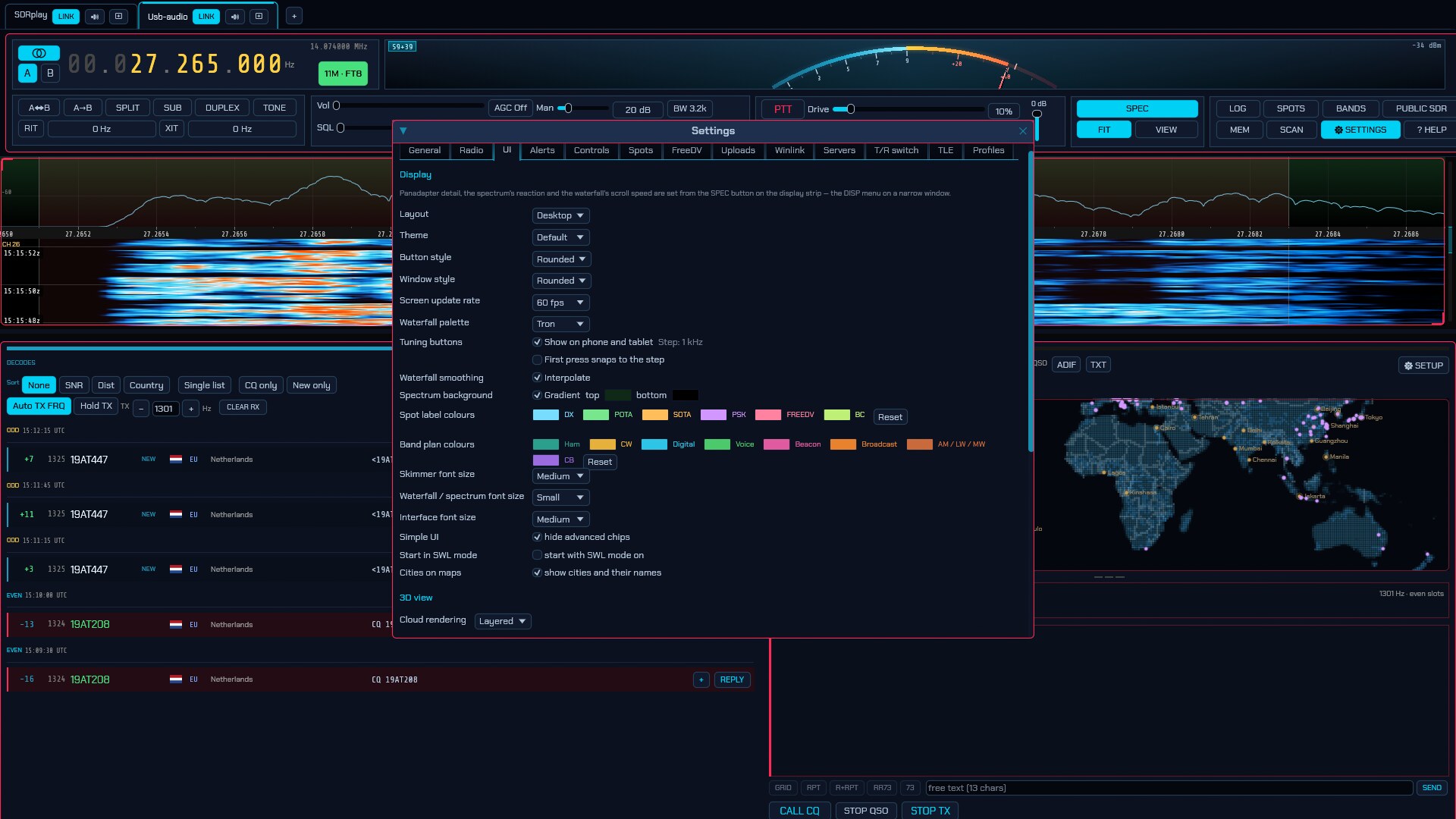
The UI tab holds display preferences, stored in config.toml under [ui], and the
spoken announcements below them under [speech]:
- SWL mode — Short Wave Listener mode. Tick hide all transmit controls and
every transmit control in the interface disappears — the PTT, CALL CQ, the
TX level, SEND, BEACON, all of it (stored as
swlunder[ui]). What remains is a clean receive-only UI, which is what an operator with a listening dongle — an RTL-SDR, a SpyServer, a KiwiSDR — actually needs. The radio can still transmit if the hardware supports it; this only hides the buttons, so a ham who also listens leaves it off. It is the companion to the broadcast bands on the selector (§2.4) for a licence-free station. It also swaps the strip’s ham chips for the listener’s — the SPOTS and AWARDS give way to SCHEDULE and SWL LOG — and Start in SWL mode below makes every session open this way, as--swldoes for one run. - Simple UI — tick hide advanced chips and the top strip drops the
controls a CB operator or a short-wave listener never opens: the ☀ 3D view,
the WIDE strip, the CTR centre-lock, the SKIMmers, and the
AWARDS, SAT, ISM and MAIL chips (stored as
simple_uiunder[ui]). What stays is what the hobby actually uses — tuning, mode, volume, squelch, bandwidth, the waterfall and its level slider, memories and scanning. Nothing is turned off, only hidden: clear the tick to bring the chips back. The radio keeps working exactly as before, so it is safe to leave on and switch off for a moment when you want the extras. - Wake lock — tick keep the screen on and a phone or tablet left on the
waterfall does not dim and lock itself (stored as
keep_screen_onunder[ui], off by default). Browser only, and it needs an https page; the line beside the box says when it is unavailable or refused. Kept with your profile on the server, like the rest of the screen. - Sound welcome — tick welcome message for the sound (on by default,
stored as
sound_welcomeunder[ui]) and the web page, when it opens or is reloaded with F5, says in the middle of the screen how to start the sound (9.3). Untick it once you know: the sound still waits for your first touch, and that touch then works as usual. Kept with your profile on the server. - Start in SWL mode — tick start with SWL mode on and every session
comes up with SWL mode already on (stored as
start_swlunder[ui]). Off unless asked for; the SWL mode switch above still turns it off for a session, and the next start honours this setting again.--swldoes the same for a single run without touching it. - SWL mode — tick hide all transmit controls to turn the listener’s
screen on for the radio on screen now, without restarting. It is the same
per-radio switch as Settings → Radio → Transmit controls (stored as
hide_txwith the radio, not with the screen), so one listening radio can sit in this mode while a transceiver beside it keeps its transmitter. The box does not appear on a remote or browser client that has not received the radio’s configuration yet. -
Layout — which control strip the window wears. Auto picks one from the window size and is what you want; Desktop, Tablet, Small screen and Phone force it, to see how the compact strips look without a phone to hand, or to keep the menus in a small desktop window rather than a strip wrapped over three rows. See 9.6 for what each one shows.
Small screen is Tablet with everything pulled in — the single-row strip and its compact readout, and the operating panels’ buttons and row spacing tightened. It is for a screen like 1366×768, which is wide enough for the roomy layout and short enough that a decode list and a waterfall are fighting over about six hundred points. Auto already tightens the panels on any window under about 820 points tall, so a small laptop gets most of this without being told; the setting is for the rest of it, and for anyone who wants the tighter panels in a window on a large screen.
Whatever the layout, no control is ever off the bottom of an operating panel. The panel keeps a floor under its own height — taken from the waterfall above it, which is the thing that can shrink — sized to the rows that layout actually draws, so a touched layout’s taller chips get the extra points they need. Where a panel still holds more than it can show at once (the WSPR beacon’s controls, the SSTV compositor), it scrolls rather than running off the edge. The divider between the waterfall and the panel is draggable in every mode: put the pointer on the
— — —handle between them and drag to give either one more of the window. -
Theme — the colour scheme for the whole UI: Default (the navy, cyan and hot pink every screenshot in this manual shows), Light (white panels and near-black text, for a bright shack or a screen read in daylight), High contrast (white on black, at the widest separation the screen can give), Green phosphor and Amber phosphor (monochrome CRT looks), Teal / orange, Rainbow (the accents spread across the spectrum), Calm (deep blue grounds and near-white ink, the blue-dominant look SDRuno wears), or one of ten schemes after the editor palettes of the same names: Nord, Nord dark, Gruvbox, Everforest, Solarized dark, Dracula and Catppuccin mocha on dark grounds, and Solarized, Catppuccin latte and Modern minimalist on bright ones. Where a palette’s own accent would be too faint to read on its panel it is lightened (or, on a bright ground, darkened) just far enough to be, so a scheme can differ a shade from the editor theme it is named after. The meters, scopes and maps take their colours from the same scheme. Applied the moment it is picked, no restart. Every theme keeps transmit, SWR and error indications red on purpose — whether RF is leaving the antenna is never left to a shade of green. Content colours (the waterfall palette below, the band plan) are their own and do not change with the theme.
- Button style / Window style — the shape the buttons and the floating
windows wear, chosen separately: Angled (the classic cut-corner look,
with a lit chamfer bracket at each cut), Rectangular, Rounded,
Gradient (a vertical shaded fill), 3D bevel (a raised lit edge) or
Terminal (drawn as if the screen were a character display — buttons read
[ LABEL ]and invert when they are on, tick boxes read[X], a slider is an=====#=====gauge, a dropdown ends in av, tabs are folder edges made of+,-and|standing open at the bottom, a multi-line text box is framed the same way, and it is all set in the monospace face). Also applied immediately. The button style reaches past the buttons: text boxes, tick boxes, sliders and dropdowns all wear it too, with the controls you type into or drag along sunk into the panel and the ones you press standing proud of it — so Gradient and 3D bevel read as depth rather than as decoration. Picked as the Window style, Terminal frames every panel, window and popup the way a character display frames one: a+at each corner, a run of-along the top and bottom and a column of|down each side, laid on the edge itself. - Screen update rate — the GUI/spectrum frame rate (5, 10, 15, 30, 60 or 90 fps). Higher looks smoother and costs more CPU/GPU. The rates below 30 are there for machines that cannot keep up — a single-board computer, a big screen on modest graphics: the radio itself is unaffected (the engine still processes every sample and audio never stutters), you simply see fewer spectrum frames, and the waterfall repeats rows to keep its scroll speed.
- Panadapter detail, the spectrum’s reaction and the waterfall’s scroll speed are not here: they moved to the SPEC popup in the Display module, beside the picture they change — see §2.8.
- Waterfall palette — the waterfall colour scheme (see 2.8 and the appendix).
- Tuning buttons — the − / step / + row under the control strip on a phone or tablet (9.6), with the step it is currently set to shown beside the box. Never drawn on a desktop.
- Waterfall smoothing — on by default. Every screen pixel is blended with the bins and rows around it, which is what makes a signal look continuous where the display is wider than the transform. Untick Interpolate for a rectangular waterfall — one block per bin, one per row — which is what reading a signal’s signature off the picture needs: an interpolated signal cannot be told apart from a genuinely wider one, and the smoothing is why a waterfall can look lower-resolution than the transform behind it really is. A bigger FFT (the VIEW chip, 2.8) is the other half of that, and the two are worth setting together.
- Spectrum background — a vertical gradient behind the spectrum line, filled from the top colour down to the bottom colour (default dark red → black). Untick Gradient for a plain background.
- Spectrum line — tick Fill to colour the band under the spectrum line, pick its colour (cyan by default) and how it is shaded — Fixed, Gradient (the default) or Mixed, as the SPEC popup’s line row describes. The line itself stays cyan. The FILL chip in the SPEC popup switches the same setting.
- Spot label colours — the tint each spot source wears, everywhere it is drawn at once: the boxes along the bottom of the waterfall, the badges in the SPOTS list and the dots on the world map. Click a swatch to pick a colour; the source’s name beside it is written in what you picked, so the row is its own preview, and Reset puts all six back to their defaults. The colours are this screen’s preference, like the theme — a remote client picks its own, and the station is not touched.
- Band plan colours — the shade each class of allocation is painted in on
the band-plan strip along the bottom of the waterfall: Ham, CW,
Digital, Voice, Beacon, Broadcast, AM / LW / MW and
CB. Same picker and same Reset as the spot colours above, and the same
standing — the plan itself comes from the station’s
bandplan.json, but what colour a block is drawn in is whatever the operator looking at it can read. Bear in mind that the blocks are drawn semi-transparent over the waterfall, so a colour lands a good deal darker there than in the swatch: the stock burnt orange for broadcast reads as brown over a near-black band, which is what this setting exists to fix. - Skimmer font size — how large the spot and decode boxes the skimmer paints on the waterfall are: Small, Medium or Large. Larger boxes are easier to read across the shack and cover more of the band while they sit there.
- Waterfall / spectrum font size — the labels painted onto the panadapter: the frequency scale, the band plan, the marker and measurement readouts.
- Interface font size — everything else: the menus, the dialogs, the floating windows, the radio tabs, the top bar and every button and readout on it. It is the whole interface’s scale, not the text alone, so the padding around a label grows with it and nothing outgrows the box it sits in. Applied the moment it is picked, no restart. The two sizes above are relative to it, so a Large interface with a Small waterfall font still has larger frequency labels than a Medium one. Bear in mind that Large leaves the window fewer points to lay out in, so a small window may drop to the tablet control strip (9.6) — force Layout: Desktop above if you would rather keep the full strip.
-
Cities on maps — draw the world’s cities on the flat maps: FT8/WSPR (3.2), APRS, ADS-B and AIS. A dot per place, sized by population, with its name beside it where there is room.
On by default, because on a map of the whole world the cities are most of what says where a dot is — a coastline alone leaves you counting inlets. They are also the busiest thing on that map, and the panel maps are small: an operator watching where their contacts are coming from is reading a handful of coloured dots against a field of grey ones with names attached. Turn this off and the land, the rivers, the borders and your stations stay; the cities and their names go. The 3D globe is unaffected — its cities are night-side lights rather than markers, and nothing there is written across a contact.
Under 3D view:
- Cloud rendering — how the
CLOUDSlayer of the solar-system window (7) draws the weather. Layered stacks slices through the troposphere and is the cheap option. Volumetric walks a ray through it instead, so the Sun casts the cloud tops onto the deck below and lightning glows out through the storm making it rather than only brightening its outside — at several times the cost per pixel. Both draw the same weather; this only chooses how much the GPU spends on the light in it.
Undocked — modules in their own windows
Any of the big modules can be pulled out into its own OS window:
- the Panadapter — SP1, the spectrum and waterfall;
- the AUX SP — a second spectrum and waterfall, the same radio seen twice;
- the Operating panel (the mode’s decoder list, transcript and controls);
- the Controls — the whole top strip: the frequency readout, the S-meter and the receiver and transmitter controls (SDRuno’s “RX control”);
- the Band & mode selector — the band list and the mode rows in a window of their own, where they lay out in five columns.
Set each under its row on this tab — Docked in this window (the default) or Undocked — its own window. Closing an undocked window docks it again, and its size and place are remembered for next time.
You can also do it from the window itself: the 🪟 WINDOWS chip at the right of the radio-tab strip — the row of radio names at the top of the main window — opens a list of the module windows (SP1 — the spectrum, SP2 (AUX) — a second spectrum, Operating panel, RX control, Band & mode), each with a DOCKED / IN ITS OWN WINDOW toggle, and DOCK ALL WINDOWS to bring them all back. The chip is lit while any of them is out of the main window. It acts on the radio you are looking at.
This is the same arrangement as the rows on this tab, from the face of the program — a window arrangement is something you change while watching the program, not while watching a settings page.
Undocking the Controls is the biggest change: the main window loses its top
strip and becomes the spectrum and the decoders, while the strip lives in the
control window — which is SDRuno’s RX control, and it carries the
band keypad and the band/mode selector with it, so the controls and the
bands are one window. The keypad is SDRuno’s too: Bands and MHz above,
ten keys laid out like a calculator (7 8 9 / 4 5 6 / 1 2 3, with 0 centred
underneath), Clear and Enter below. Each key names the band it goes to
and the bands rise with the digits, so 1 is 160 m and 9 is 11 m; a press
tunes there, staying in the mode you are in. Press MHz and the same keys type
a frequency instead — in kilohertz, so 14074 is 14.074 MHz — and Enter
tunes it and puts the keys back to bands. The full band list stays beside the
keypad rather than behind it: the keypad carries the ten HF allocations, and
everything else (60 m, the VHF and UHF bands, the CB channels, the broadcast
services) is a chip in the list as it always was. A key for a band your radio
cannot receive is greyed, and says which range the radio published.
The main window keeps its radio-tab strip and, when nothing is left in it, shows
a plain face rather than a black hole (the band selector is already in the
control window). Undocking the other two is the same idea one module down.
Undocking the Controls does not first flip it to a phone-shaped strip: the
control window is a desktop console whatever its own height, because it opens
wide and short and a compact strip there was the first thing to look wrong.
Undocking the band/mode selector is the widest surface of all: as a docked column it cannot be much more than 280 pt — the operating panels below it are built for about 680 pt, and a wider column squeezes them — so its window is where the mode sections lay out in five columns (SDRuno’s band panel). Open it from the ⇱ WINDOW chip in the band popup, from the docked column’s header, or from the 🪟 WINDOWS menu. While it is out the docked column is not drawn, so there is one selector on screen; closing the window docks it again.
When everything is undocked there is nothing left of the radio to draw in the main window’s centre, so the band/mode selector fills it rather than leaving an empty panel. A voice mode, which has no operating panel, opens no panel window at all; a notice says so once. The undocked panadapter window carries a large frequency readout with the mode and signal level beneath it, so the second monitor says what you would otherwise glance back at the main window for. A Dock all windows / UNDOCK ALL WINDOWS buttons appear under the rows: one brings every module home, the other puts every module in a window of its own (a module with nothing to show, like the operating panel in a voice mode, opens no window). Each is shown only while it would do something. The same pair is in the 🪟 WINDOWS menu on the radio-tab strip.
Workspaces save a whole arrangement and put it back: under the undocked
rows, type a name and SAVE CURRENT to store which modules are in their own
windows and where those windows are, then click a saved name to recall it. The
× beside a name forgets it, and a name you save again replaces the earlier
one. Up to ten — SDRuno’s limit. A workspace is the window arrangement only;
what is on is the station’s, not the workspace’s. They live in
workspaces.json beside the rest of the configuration.
The tool windows — the scanner, the schedule, the logbook, the spots list,
the signal-id guide and the rest — can go to their own windows too. Each carries
a small ⇱ WINDOW chip at its top-right: click it and the tool moves into its
own OS window (where the chip reads ⇱ DOCK to bring it back). Closing an
undocked tool closes it, as the ✕ does when it is docked. A tool window is
session-only, like its position inside the main window — where it sat is not
remembered across a restart. Their app-ids are sdroxide-tool-<name> (e.g.
sdroxide-tool-scanner, sdroxide-tool-mail), so one rule can float them all.
Every menu tool window has one, and each remembers its own size: Settings, SCHEDULE, RECORDINGS, SPOTS, PUBLIC SDRS, the voice keyer, and the AIS / ADS-B / VDL2 / FSQ Contacts and per-mode setup panels. The WEFAX chart viewer is the one exception and stays docked — it belongs to the chart you picked rather than to the menu, so it opens and closes with that chart.
Settings is the one worth putting on a second monitor: it opens in the middle of the screen the first time and will not be dragged narrower than its tabs can use, so the whole box survives a move rather than becoming a column of clipped controls.
| Tool window | Application id |
|---|---|
| Settings | sdroxide-tool-settings |
| Schedule | sdroxide-tool-schedule |
| Recordings | sdroxide-tool-recordings |
| Spots | sdroxide-tool-spots |
| Public SDRs | sdroxide-tool-public-sdrs |
| Voice keyer | sdroxide-tool-voice-keyer |
| AIS setup | sdroxide-tool-ais-setup |
| ADS-B setup | sdroxide-tool-adsb-setup |
| VDL2 setup | sdroxide-tool-vdl2-setup |
| FSQ contacts | sdroxide-tool-fsq-contacts |
| Digital-mode setup | sdroxide-tool-digi-setup |
The app does not place the window on Wayland. A Wayland client is given no absolute position, so on niri, sway or GNOME the window opens where the compositor tiles it. To float it and pin it to a monitor, give it a window rule matching its application id:
| Module | Application id |
|---|---|
| Panadapter (SP1) | sdroxide-panadapter |
| AUX SP (second spectrum) | sdroxide-panadapter-aux |
| Operating panel | sdroxide-panel |
| Controls | sdroxide-controls |
| Band & mode selector | sdroxide-bandmenu |
| Tool windows | sdroxide-tool-<name> |
For niri, in ~/.config/niri/config.kdl (use your own output names —
niri msg outputs):
window-rule {
    match app-id="sdroxide-panadapter"
    open-floating true
    open-on-output "HDMI-A-1"
    default-column-width { fixed 1200; }
    default-window-height { fixed 720; }
}
window-rule {
    match app-id="sdroxide-controls"
    open-floating true
    open-on-output "HDMI-A-1"
    default-column-width { fixed 1400; }
    default-window-height { fixed 150; }
}
window-rule {
    match app-id="sdroxide-panel"
    open-floating true
    open-on-output "DP-1"
    default-column-width { fixed 560; }
}
On X11, Windows and macOS the position is honoured directly and no rule is needed.
Voice announcements
The last section of the UI tab reads the radio out loud, so it can be operated without seeing it. Tick Speak changes to the radio to switch it on; it is off until you ask for it.
The voice is a neural one that ships with sdroxide and runs on your own machine. Nothing is sent anywhere, no speech service has to be installed, and it works with no network at all.
- Voice — Shipped voice, or any other Piper voice you have dropped into
speech_voices/in the config directory (an.onnxand its.onnx.json, side by side). Changing it restarts the voice, which takes a moment. - Speed — 0.5× to 2×. The voice stretches or compresses its own phrasing rather than being played faster, so the pitch does not change. Past about 2× it stops getting shorter — that is a limit of the voice, not of the slider.
- Volume — independent of the AF gain.
- Output — which sound device announcements come out of. Because speech has its own output stream it can be a different device from the receiver: announcements in the room, the band in the headphones.
- Detail — Terse says only what changed; Normal adds the numbers that go with it; Full adds units, band segments, and the settings that normally stay quiet.
- Duck receiver — dip the receiver while an announcement plays, and by how much. This never reaches a recording, but anyone listening to your station remotely does hear the dip.
- Test speaks a sample line. Beside it is the voice that loaded, or why one did not.
What to announce, the collapsing section below, is a switch per category. The defaults are what most operators want: frequency, mode and band, VFO and split, AGC, the drive/tune/mic levels, transmit and receive, RIT and XIT, memories and scanning, band-edge warnings, and the engine’s own messages. Filters, squelch and noise reduction are off, because they move constantly while chasing a signal.
Some behaviour worth knowing, because it is deliberate:
- The frequency waits for the dial to stop. Scrolling says nothing until you let go, then reads the frequency once. Spin two kilohertz up and back and it stays quiet, because you settled where you already were.
- One button press is one phrase. A band change moves band, frequency and mode together and is read as “forty meters, seven point one zero zero, L S B”, not as three separate announcements.
- Leaving an amateur band warns once, on the way out, and keying up outside one warns immediately rather than waiting for the dial to settle.
- SWR is read out while TUNE is held — every two seconds by default, with the best match reached announced when you let go. A match that goes above 3:1 interrupts with a warning, and clears again below 2.5:1. On a rig with no SWR bridge you are told so once and then left in peace.
- Speech stops while you transmit, since it goes to your speakers and therefore into your microphone. High-SWR warnings still get through.
- Decoded messages: FT8 calls addressed to you, JS8 and FSQ messages addressed to you. Ordinary CQs are not read — a busy evening on twenty metres is a hundred a minute — but you can switch them on.
- Reading CW and RTTY aloud is off by default. A decoder produces text faster than speech reads it, so anything that falls too far behind the live audio is dropped rather than queued: you hear what is being sent now, not what was sent a minute ago. CW is only read while the decoder reports lock.
Callsigns are read in phonetics — “kilo one alpha bravo charlie” — because a callsign is the one thing that must not be misheard. Frequencies are read the way an operator reads a dial, digit by digit after the decimal point, and always “zero”, never “oh”. Both can be changed under How things are read.
Keys for Speak status, Repeat last announcement, Stop speaking and Announcements on/off are on the Controls tab (6.4) under Speech. They have no defaults; bind the ones you want.
sdroxide also exposes its whole window to the platform screen reader — NVDA on Windows, Orca on Linux, VoiceOver on macOS — so the controls can be navigated and read as well as heard.
Audible alerts
The Alerts tab is the other half of the same idea, aimed the other way: the announcements read out what changed, the alerts ring when a decode matters. They listen to the FT8, FT4, FT2 and JS8 decodes, and they ring whether or not sdroxide’s window is in front — reaching you while you are looking at something else is what they are for. Tick Sound an alarm when a decode matters to switch them on; they are off until you do, and they need your callsign (6.1) to know which calls are for you.
- Volume — independent of the AF gain.
- Output — the sound device the alarm plays on. It has its own output stream, so it can be a different device from the receiver: the band in the headphones, the alarm in the room.
- Test plays the sound set for a station calling you. Beside it is the device in use, or why it could not be opened.
What to sound has a switch, a sound — Ding, Two-tone, Triplet, Warble or Digital, all generated on the spot — and a reply for each of five events:
| Event | On by default | Rings for |
|---|---|---|
| A station is calling me | yes | A decode addressed to your callsign, including a Fox’s RR73 to you in Hound mode |
| A CQ I could answer | no | A plain CQ, an activity CQ (CQ POTA, CQ TEST …), CQ DX from another entity, or a CQ aimed at your continent or your country — the same test the decode list uses. Off because a busy band is a hundred of these a minute |
| New DXCC entity | yes | A station from an entity your logbook has never had, on any band |
| New entity on this band | yes | An entity in the log, but not from this band |
| New grid square | yes | A grid square the log has never had |
A decode that is several of these at once rings for the first in that list, in the order calling you, new entity, new on the band, new grid, CQ. One batch of decodes rings once, for the most important match in it wherever it sits in the list — a slot full of new stations says no more as sixteen alarms than as one. After it rings, that station stays quiet for that event for a while — a minute for a call, 45 seconds for a CQ, two minutes for a grid and five for an entity — so a new entity calling CQ all evening does not ring all evening.
Tone, voice or both. Each event’s reply is Tone (the alarm sound above, and the default), Voice, or Tone + voice. Voice reads the alert through the spoken-announcement voice (Settings → UI → Voice announcements) — “Juliett Alfa One, calling you”, “Juliett Alfa One, new DXCC, Japan”, “Juliett Alfa One, new one on 20 metres”, “Juliett Alfa One, new grid”. The callsign leads every phrase, so the one thing you act on is never the part that is clipped, and the spoken alert fires from the alarm path, so it too is heard whether or not sdroxide’s window is in front. With the voice switched off a Voice reply is silent — there is no tone to fall back on — so pick Tone + voice if you would rather hear something either way; the sound is greyed on a voice-only row because it is not used. A phrase is not spoken while you transmit, because it would go out through the microphone. And so you are choosing on more than a label: any event that speaks also shows the words it will say beneath it, and its SAY button reads them out through the announcement voice — so you can hear what you are switching on without waiting for the band to produce one. The button is greyed until the reply speaks and the voice is on, and it then says which of the two is missing.
The settings are stored in config.toml under [alerts] and belong to the
screen in front of you, like the announcements. On a station with several radios
there is one alarm for all of them: every radio tab shares the same settings and
the same output. A browser client keeps the settings but has no sound for them
yet.
6.4 Controls: keyboard, mouse and MIDI
Everything sdroxide can be told to do is an action — tune, PTT, change band, cycle noise reduction, open the logbook — and the Controls tab binds actions to whatever you would rather press or turn than click. The three sections of the tab (keyboard, mouse, MIDI) all draw on the same list of actions.
Actions come in two kinds, and the Step / mode column changes to match. A continuous action (tuning, volume, filter width) takes a step — the amount one keypress or one detent moves it — and a down tickbox to make that control move it the other way, which is how the left and right arrows share one action. An accel above zero makes a held key move further the longer you hold it. A momentary action (PTT, mute, split) is either Hold — asserted while the key is down — or Toggle, which flips on each press.
6.4.1 Keyboard
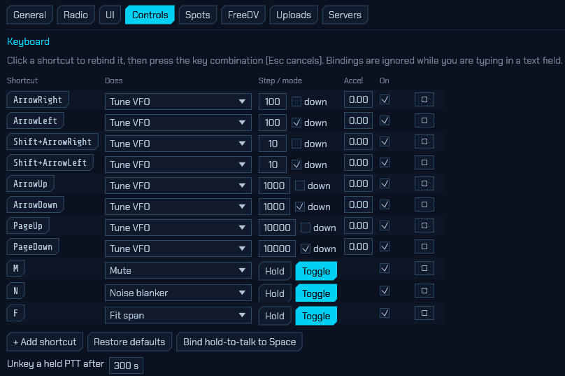
The table lists every shortcut, one per row: the key Shortcut, what it Does, its Step / mode, its Accel, and an On tickbox to disable a binding without deleting it. Click the shortcut button to rebind it, then press the key combination you want (Esc cancels). + Add shortcut creates a row, ✕ removes one, and Restore defaults puts back the shipped set listed in 16. Shortcuts are ignored while you are typing in a text field or a control has keyboard focus.
Push-to-talk deserves a note. No PTT key ships bound, on purpose: a transmitter keyed by accident is the worst thing this feature could do to you. (The voice-keyer digits are bound out of the box — see 2.11 — because a key over an empty slot does nothing, and a new installation has ten of them.) Bind hold-to-talk to Space sets it up in one click. A held PTT is released when you let go, when the window loses focus, when a text field takes the keyboard, and after the Unkey a held PTT after timeout at the bottom of the section (300 s by default, 0 disables it) — so alt-tabbing mid-over drops you back to receive rather than transmitting your office.
6.4.2 Panadapter mouse and mouse buttons
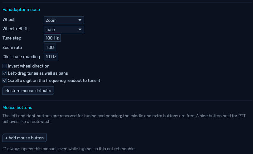
Panadapter mouse sets what the wheel does over the spectrum:
- Wheel and Wheel + Shift — the plain and shifted wheel actions; by default zoom and tune. Swapping them is a single dropdown if you would rather scroll to tune.
- Tune step — the Hz per wheel detent, and the grid wheel tuning lands on. A dial left between two grid points — by a click on the waterfall, say — goes to the next point in the direction you turn on the first detent: from 14.262.500 one 1 kHz step up is 14.263.000, and one down is 14.262.000. The keyboard’s tuning keys work the same way (issue #431).
- Zoom rate — scales how far one detent zooms.
- Click-tune rounding — the step click-to-tune snaps to.
- Invert wheel direction — flips both wheel actions.
- Left-drag tunes as well as pans — turn it off to make left-drag pan only, like right-drag. It also turns off the dial’s coast, since there is no longer a dial being turned.
- Scroll a digit on the frequency readout to tune it — the wheel over a digit of the VFO readout steps that digit.
- Restore mouse defaults puts the whole section back.
Mouse buttons binds the buttons themselves. The left and right buttons are reserved for tuning and panning; the middle and extra (side) buttons are free, so + Add mouse button picks a button, an action and Hold/Toggle — a side button held for PTT behaves like a footswitch.
F1 always opens this manual, even while you are typing, so it is not rebindable. While the manual is open, the arrow, Page and Home/End keys scroll it instead of running whatever you have bound them to, and Ctrl+F / F3 drive its search bar.
6.4.3 MIDI controller
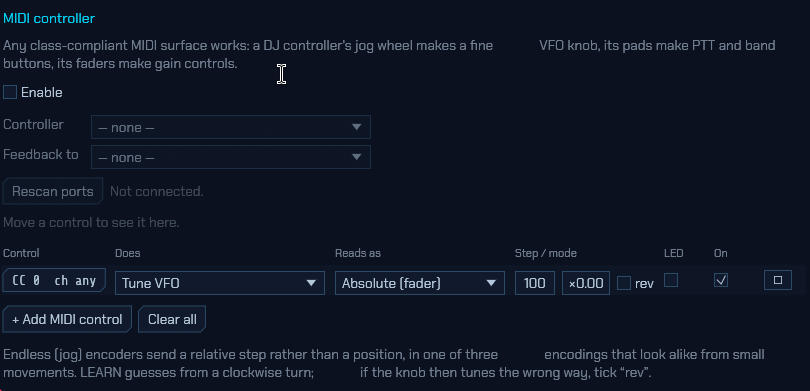
Any class-compliant MIDI surface works, and they are the cheapest real VFO knob there is: a DJ controller’s jog wheel tunes, its pads make PTT and band buttons, its faders make gain controls. MIDI needs the native app — the browser client has no MIDI access.
- Enable — the rest of the section stays greyed out until this is ticked.
- Controller — the input port to listen to. Rescan ports re-enumerates if you plugged the surface in after opening the dialog, and the line beside it reports the connected port or the reason it failed.
- Feedback to — the output port for LED/motor feedback (see below).
- Last message — names whatever control moved last, which is how you identify an unlabelled knob.
Each row of the binding table is one control: the Control button (click it, then move the control you want — LEARN captures it), what it Does, how it Reads as, its Step / mode, an LED tickbox, and On. + Add MIDI control adds a row and Clear all empties the table.
Endless “jog” encoders send a relative step rather than a position, in one of three encodings that are indistinguishable from small movements. LEARN guesses from the direction you turn; if the knob then tunes backwards, tick rev. A plain fader or knob that sends a position instead should be set to Absolute (fader).
Tick LED on a binding to send the current value back to the controller, so a PTT button lights while you transmit and a motor fader follows the volume. Not every surface likes being written to, which is why it is off by default.
A controller unplugged mid-QSO releases anything it was holding and reconnects by itself when you plug it back in.
Bindings live with the client. They are stored in
input.jsonon the machine running the user interface, not the one running the radio — so a knob plugged into your laptop works just as well against a remote engine (--connect, 8). Keyboard and mouse bindings work in the browser client too; MIDI needs the native app.
6.5 Spots: spot feeds
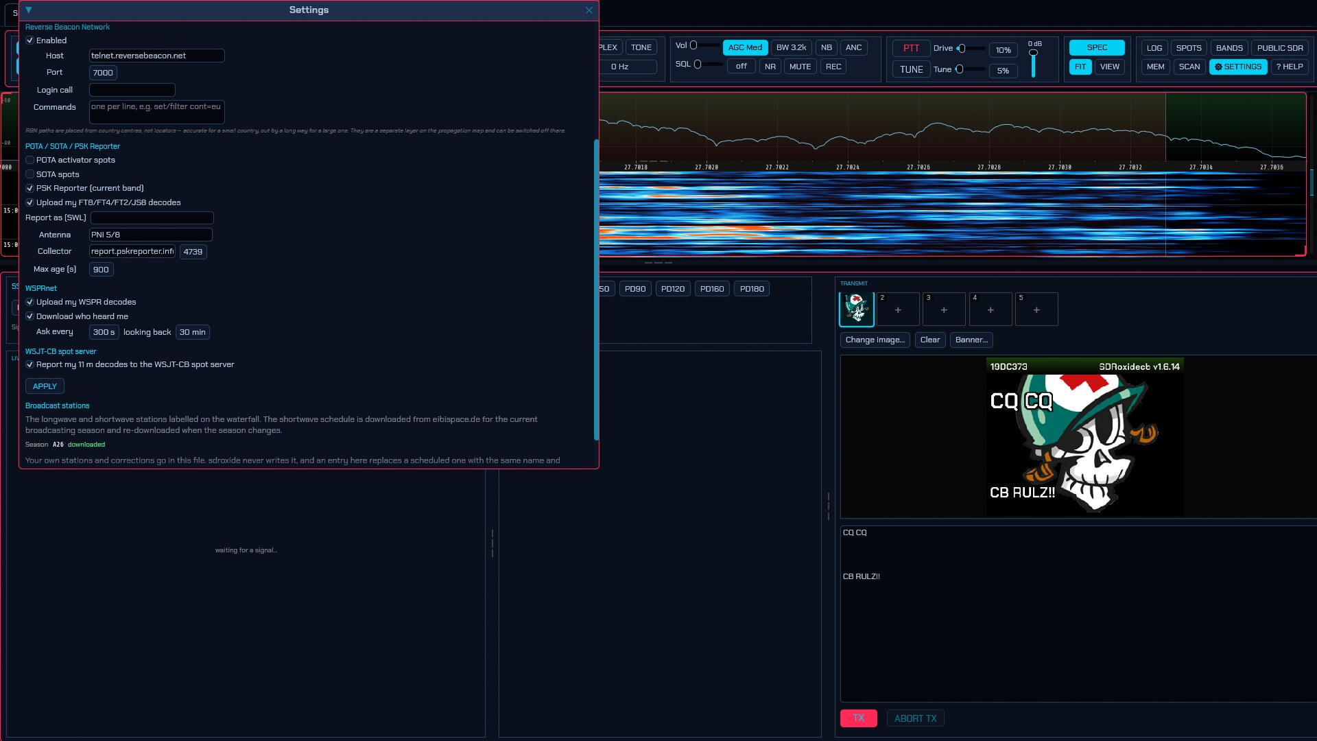
The Spots tab turns on the feeds that put other stations on your panadapter and in the SPOTS window. What the spots then do — clicking one to work it, the filters, the world map — is §10.1.
- Operator — shown for reference only; your callsign and grid are set once on the General tab and used everywhere, including to log in to the DX cluster.
- DX cluster (telnet) — tick Enabled, then enter the node Host and
Port (commonly 7300/7373/8000). Login call overrides the operator
callsign if needed, and Commands (one per line, e.g.
SET/FT8) are sent after login to set node-side filters. -
Reverse Beacon Network — the worldwide network of CW/RTTY skimmers, on by default. It puts nothing on the air, needs no account, and logs in with the callsign from the General tab — nothing to set up, and nothing happens until that callsign exists. Port
7000is the CW and RTTY feed,7001the FT8/FT4 one. Login call overrides the operator callsign, and Commands narrows the feed (set/filter cont=euand the like).RBN is not a spot feed and its spots do not appear in the SPOTS window: there are thousands a minute and they are measurements rather than invitations. They go to the propagation heat map, which is what lets it show bands this radio is not listening to. Read that section for the one real caveat — RBN lines carry no locators, so paths are placed from country centres.
- POTA / SOTA / PSK Reporter — tick each feed to poll it. POTA activator spots and SOTA spots show current activators; PSK Reporter (current band) shows who is being heard on the band you are on. Max age (s) drops spots older than that many seconds.
- APPLY connects or disconnects the feeds and saves the settings.
- Broadcast stations — which broadcasting season’s schedule is in use and whether it was downloaded, where your own station file lives, Reload to re-read it after an edit, and Download schedule now to refetch the season immediately. See §10.6.
FreeDV Reporter is a spot source too, but has its own tab — 6.6.
Where your reports say you heard it. Every network above that you upload to — PSK Reporter, WSPRnet, FreeDV Reporter, the WSJT-CB spot server — is told a locator, and that locator is your own only while the antenna is yours. A radio pointed at an online receiver reports from the receiver’s square instead, and one whose receiver publishes no position reports nothing at all. That is the Antenna is row on Settings → Radio (6.2); it is filled in for you when you take a receiver under PUBLIC SDR.
WSPRnet. Two independent halves, both using the callsign and grid from the General tab:
- Upload my WSPR decodes — on by default. Every reception goes to wsprnet.org, and so does a slot that decoded nothing, which is how the network distinguishes a shut band from a receiver that was switched off. This puts nothing on the air.
- Download who heard me — off by default, because it is a poll of somebody
else’s server on a timer. Turn it on and reports of your own callsign appear in
the WSPR panel with a
→, and their reporters go on the map. See §3.11.
WSJT-CB spot server. One switch, off by default:
- Report my 11 m decodes to the WSJT-CB spot server — posts each spot decoded
on the 11 m band to the CB community’s spotting service (
xzgroup.net), the same server WSJT-CB’s own client can feed. Your callsign is the spotter, and your grid goes with it when you have one. It is a third-party service and nothing leaves the station until you tick it; PSK Reporter above is a separate switch and the two are independent. Reporting is receive-side only, so it needs no transmit permission, and only spots on the 11 m band are sent.
6.6 FreeDV: FreeDV Reporter
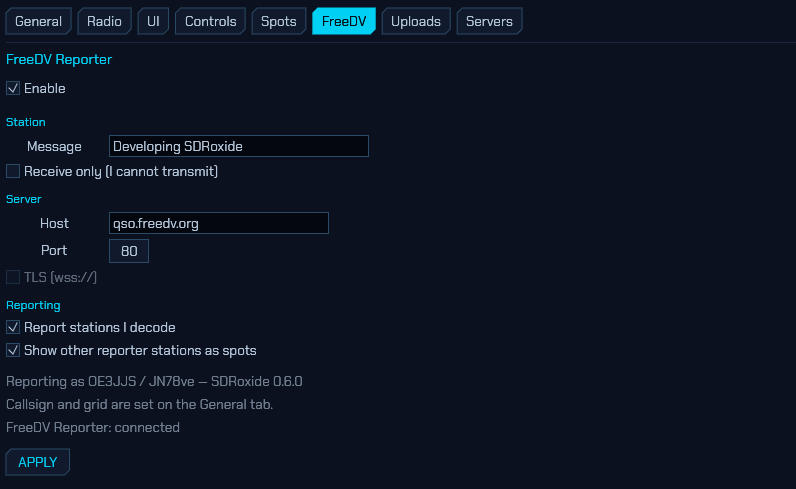
FreeDV Reporter is where FreeDV operators announce where they are listening and who they are hearing; sdroxide talks to it in both directions. What that gets you is §10.5; the tab itself is:
- Enable — connects while ticked. You are only shown to others while the radio is in RADE mode, so the site never lists you as working FreeDV when you are actually on CW.
- Station → Message — a free-text status shown beside your callsign. Receive only (I cannot transmit) marks you as a listener. You are reported under the callsign and grid from the General tab; without both, the connection is view-only — you see other stations but do not appear yourself.
- Server → Host and Port — the public server (
qso.freedv.org:80) by default. TLS (wss://) is greyed out: it is not implemented yet, and FreeDV GUI uses plainws://too. - Reporting → Report stations I decode sends a reception report for each callsign recovered from a received End-of-Over frame. Show other reporter stations as spots adds them to the panadapter, world map and SPOTS window under the FREEDV filter.
- The status lines underneath show exactly how you are being reported
(
OE3JJS / JN78ve — SDRoxide 0.8.0) and whether the connection is up. - APPLY connects or disconnects and saves.
6.7 Uploads: callsign lookup and QSL services
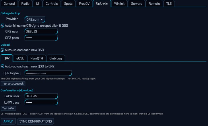
The Uploads tab holds every online account the logbook uses. All of it is
stored in plaintext in net.json. How the features behave is
§10.2 and
§10.3; the fields are:
- Callsign lookup → Provider —
QRZ.com(needs a QRZ username and password with an active XML-data subscription) orHamQTH(free). Only the chosen provider’s login is shown, because lookups go to exactly one service — pick the provider first and its username and password appear under it. Auto-fill name/QTH/grid on spot click & QSO looks a call up by itself instead of only on the LOOKUP button. - Upload — Auto-upload each new QSO is the master switch, and under it
is a tab per logging service: QRZ, eQSL, HamQTH,
Club Log, WRL and LOG11DX. Each tab holds everything about that
one service — whether a new QSO is pushed to it, its login, and the button
that checks that login. So setting up a service means opening its tab and
filling in what is on it, rather than picking your fields out of all four
services’ at once.
- QRZ — the QRZ log key, your QRZ logbook API key. Not the XML-lookup login above; the two are unrelated.
- eQSL — eQSL user and pass.
- HamQTH — HamQTH user and pass, which are the same two boxes as the ones under Callsign lookup. HamQTH issues one login per operator and its logbook authenticates with it, so type them into whichever pair you reach first and the other fills in with it. Nothing extra is needed: a HamQTH callsign lookup that works is already a HamQTH logbook that works. (This is also why the boxes are repeated here at all — an operator who looks calls up on QRZ but uploads to HamQTH would otherwise have nowhere to type them.)
- Club Log — Club Log email, pass and key.
- WRL — the WRL API key for World Radio League, generated under Integrations → Developer API. It is a key rather than a login, and WRL shows it once when you generate it and stores only a hash, so copy it then. Contacts go to your default logbook: if you keep more than one and have not set a default, WRL refuses them and says so — set one there and it works. Test WRL says both whether the key is good and whether that default is set, which is the one thing you would otherwise find out a contact at a time.
- LOG11DX — the API URL and API token for
LOG11DX, the 11 m logbook. Both are on your LOG11DX
profile page; the URL defaults to the one its own WSJT-X bridge posts to,
and the token is masked there, so copy it when you generate it. The site’s
bridge program is not needed — sdroxide is the program that logs the QSO,
so it posts each one straight to the same API, with no UDP listener and no
second program to keep running. Only your
station_callsignand the QSO’s own fields are sent. Test LOG11DX checks the token against the site.
A service’s own tickbox only takes effect while the master Auto-upload each new QSO is on; with it off the tab says so, and the per-QSO UP button in the logbook still uploads by hand.
When a QSO completes, the panel says where it went: beside ✓ QSO COMPLETE appears ↑ logged to LOG11DX (naming each service it reached), or a red ⚠ LOG11DX not uploaded if the upload failed. The local log is written the instant the contact ends — the confirmation is about the online logbooks, which answer a second or two later. Nothing is drawn when no auto-upload is set, so a station that keeps a purely local log never sees it. A failed upload is also still in the network log, and the record can be re-sent from the logbook’s UP button.
- Confirmations (download) — LoTW user and pass. LoTW upload stays manual, by design; only the download is automated.
At the bottom of the tab, APPLY saves everything above, and SYNC CONFIRMATIONS pulls your LoTW/eQSL confirmations into the log.
Testing the credentials
Each upload service’s tab carries its own Test button — Test QRZ Logbook / Test eQSL / Test HamQTH / Test Club Log / Test World Radio League / Test LOG11DX — and there is a Test LoTW beside the confirmation login. It asks that service, there and then, whether the login you have typed works, and prints what came back — a green tick with the account the service recognised, or a red cross with its own words for the refusal.
Without it the first sign that a password is wrong is a QSO that failed to upload, hours after the contact, which is both too late and the wrong place to find out.
- Nothing is logged. Each button uses the cheapest read endpoint the service publishes; none of them can write. A credential check that inserted a dummy QSO to see whether the login worked would leave a fictional contact in your permanent log, and for the services that forward to LoTW or an award programme, somewhere you cannot withdraw it from.
- Pressing Test also applies the settings above it, since it is the applied credentials that get checked — otherwise a freshly pasted key would be tested against the old one and reported wrong when it was merely unsaved.
- Club Log’s API key cannot be checked, only the account: the documented key
endpoint refuses these requests. A pass there says
account accepted (API key
not checked)
rather than pretending otherwise, and an upload can still fail on the key alone. - Test HamQTH goes through the callbook login, not the logbook: HamQTH’s real-time logbook endpoint has no read-only mode — its only commands are insert, update and delete — so asking it would mean logging a QSO to find out whether the password works. The callbook login reads nothing, writes nothing, and answers about the same account the upload uses. So a pass proves the account, as it does for eQSL and LoTW.
- Results are not remembered between sessions — a green tick from an hour ago says nothing about the password typed since.
- The buttons appear only when the radio is attached to this machine. The credentials, and the answer naming the account they belong to, live on the station computer; a remote client is not shown either.
6.8 Winlink: radio email account
Everything the Winlink mailbox needs to identify itself and decide where to forward. What the feature does — the MAIL window, composing, the packet panel — is §11; this is the tab.
All of it is stored in plaintext in net.json, the account password
included, exactly as the QRZ, HamQTH, Club Log and LoTW credentials on the
Uploads tab are.
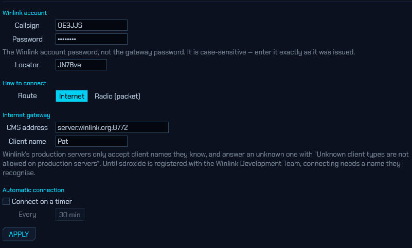
Winlink account
- Callsign — the Winlink account callsign. Upper-cased when it is used, so the case you type does not matter here.
- Password — the account password, not the
CMSTelnetgateway password. It is case-sensitive: the login challenge is computed from it, andFOOBARandFooBarproduce different answers, so it has to be entered exactly as it was issued. sdroxide does not silently upper-case it, because a guess that is wrong fails at the server with nothing but a rejected login to explain it. - Locator — reported in the session greeting. Cosmetic; nothing depends on it.
An account is created the first time a callsign connects to the CMS, and its password arrives as a service message. Winlink validates amateur licences automatically for many countries.
How to connect
Route picks the lane the CONNECT button uses:
- Internet — forward with the CMS over the internet. Needs no radio, and is how a large share of Winlink traffic actually moves.
- Radio (packet) — call an RMS gateway on the air. The radio has to be in PACKET or PACKET-HF and your station call (with an SSID) has to be set in the packet setup dialog; nothing transmits until it is. See §11.
Choosing Radio (packet) reveals the gateway fields:
- Gateway — the RMS gateway’s callsign including SSID, e.g.
OE1XAR-10. - Via — digipeaters, in order, separated by spaces. Usually empty: a gateway you can hear directly is a gateway you should call directly.
- Speed — the speed that gateway runs, which is a fact about the gateway rather than about the band: a 2 m RMS may be 1200 or 9600, and nothing but its owner’s published details tells you which. Most answer at 1200. Set it from what is published rather than guessing, because calling a 1200 gateway at 9600 sounds exactly like calling one that is off the air — no error, just silence. 9600 additionally needs the radio’s data port at both ends; a microphone and speaker path destroys it. 300 is HF.
- Frequency — where the gateway listens. Zero leaves the dial alone, which is what you want when you park on one channel; anything else tunes the radio when the session starts.
Both Speed and Frequency are applied when the session starts, not when you set them, so nothing moves the dial or the modem out from under you while you are still listening. When a connect does change either one it says so in the status line, and the session transcript names the speed it called at.
My gateways
Winlink publishes its gateway list through an API that refuses every request without an access key sdroxide does not have, so you keep your own list. That is what a packet operator does anyway — the two or three gateways reachable from one location are learned by trying, and they rarely change.
+ ADD GATEWAY saves whatever is in the Gateway, Via, Speed and Frequency fields. Each saved entry shows its digipeater path, frequency and speed; USE loads all four back into those fields, making it the one the next connect calls, and FORGET removes it. A typed callsign works exactly as well as a fetched one would, and if an API key ever arrives the fetched entries land in this same list.
Because each entry carries its own speed and channel, a list holding a 1200 gateway and a 9600 one needs no further setting-up: USE on either puts the modem and the dial where that gateway wants them.
Internet gateway
- CMS address — which server to dial,
server.winlink.org:8772unless you have a reason. Mostly here for testing. - Client name — the name announced to the CMS in our station identifier.
Client name, and why it is a field you may have to change. Winlink’s production servers accept only client names that have been registered with them, and answer anything else with
*** Unknown client types are not allowed
on production servers
. sdroxide is not registered yet, so out of the box a connection to the production CMS is refused. Until that is resolved this field is how an operator gets in. It is deliberately visible here rather than quietly defaulted to another project’s name.
Automatic connection
Connect on a timer polls for mail on its own, Every n minutes (5 to 1440). Off by default: a forwarding session keys the transmitter when the route is Radio, and nothing here should start doing that unasked.
APPLY
APPLY persists the account and hands it to the mailbox. Like every other network tab, the fields above are edited in a scratch copy until it is pressed — so an account typed in and left unapplied will look saved and still fail with “set a Winlink callsign and password” when you press CONNECT.
6.9 Servers: letting other programs drive the radio
The Servers tab makes sdroxide the radio for other software. Three sections share the tab, one above the other, and all can run at the same time.
Which server should I use? rigctld carries control only and is understood by nearly everything. The built-in TCI server additionally carries receive audio, transmit audio and a wideband IQ stream, but only a handful of programs speak it. The WSJT-X UDP broadcast is not a control surface at all: it is how loggers and mapping tools learn what you are decoding and working.
Neither control protocol has any authentication, which is why both default to
127.0.0.1.
With more than one radio configured (§2.17), each radio has its own copy of this tab and its own servers — a client connects to a port and gets that radio, so two copies of WSJT-X on two ports can drive two radios at once. Additional radios start with the TCI server disabled, since its default port is already taken by the first radio’s: enable it and pick a free port here.
6.8.1 Hamlib rigctld server
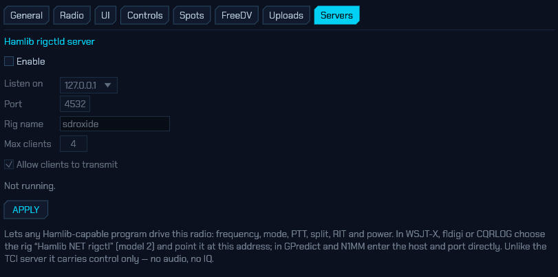
Most amateur software reaches a radio through Hamlib, over the network
protocol its rigctld daemon speaks. sdroxide serves that protocol directly, so
WSJT-X, fldigi, JS8Call, N1MM, Log4OM, GPredict and CQRLOG can drive it with no
extra daemon, no serial cable and no virtual COM port pair.
- Enable — off by default. Port 4532 is often already held by a real
rigctld, and the protocol has no authentication of any kind, so turning this on should be a decision rather than a default. - Listen on —
127.0.0.1(this machine only) or0.0.0.0(your whole network). - Port — 4532 by default, the port every rigctld client assumes.
- Rig name — what clients see from
get_info. - Max clients — how many programs may connect at once. They all see the same radio, and the last command wins.
- Allow clients to transmit — off refuses every key request and stops advertising a transmit range, so Hamlib declines to key before it even asks.
The status line shows whether the server is listening, on which address, and how
many clients are connected. Press APPLY to save and (re)bind. If the bind
fails on 4532, the usual cause is a real rigctld already running.
Supported: frequency, mode and passband, PTT, VFO A/B and split (including split
frequency and mode), RIT and XIT, the RFPOWER / AF / MICGAIN / STRENGTH
levels, the NB / NR / ANF / MUTE functions, the XCHG / CPY /
TOGGLE / BAND_UP / BAND_DOWN / TUNE VFO operations, and the voice keyer
(send_voice_mem 1…10, stop_voice_mem — see
2.11). The voice keyer obeys Allow clients to transmit
like PTT does.
Setting up clients:
- WSJT-X / JTDX — Settings → Radio, rig Hamlib NET rigctl, Network
Server
127.0.0.1:4532, PTT method CAT, mode Data/Pkt. Use Test CAT and Test PTT. - fldigi — Configure → Rig control → Hamlib, rig NET rigctl (2),
device
127.0.0.1:4532. - GPredict — Interfaces → Radios, host
127.0.0.1, port 4532. - N1MM+ / Log4OM — pick the Hamlib/rigctld radio type and enter the same host and port.
sdroxide reports every digital mode (FT8, FT4, FT2, PSK, RTTY’s neighbours, SSTV,
RADE…) as Hamlib’s PKTUSB, because that is what they are on the air. Clients
that read the mode and periodically write it back — WSJT-X does — therefore
cannot knock a running FT8 session out of its mode: setting the mode already
reported changes nothing.
6.8.2 Built-in TCI server
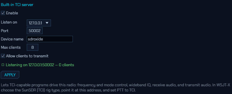
sdroxide also is a TCI server, so TCI-capable programs can use it as their radio: frequency and mode control, a wideband IQ stream, receive audio to decode, and transmit audio to put on the air. It is on by default.
- Enable — turn the whole server on or off.
- Listen on —
127.0.0.1(this machine only, the default) or0.0.0.0(reachable from your whole network). - Port — 50001 by default, the port TCI clients expect. The screenshot uses 50002 because ExpertSDR3 has 50001 on that machine.
- Device name — what clients see in the connect handshake.
- Max clients — how many programs may connect at once. They all see the same radio, and the last command wins.
- Allow clients to transmit — turn this off to let programs read and tune but never key the transmitter.
The green status line shows whether the server is listening, on which address, and how many clients are connected right now. Press APPLY to save and (re)bind.
Setting up WSJT-X: under Settings → Radio, choose the TCI Client RX1 rig,
put sdroxide’s address in TCI Server (e.g. 127.0.0.1:50002), set PTT to
CAT, and tick TCI audio so both audio devices come over TCI. JTDX and
MSHV are configured the same way. Verified against WSJT-X on this address.
If a client won’t connect, run sdroxide with
RUST_LOG=sdroxide_tci=debug — the whole TCI conversation is logged in both
directions, which is usually enough to see which command it gave up on. WSJT-X
also records the reason in ~/.local/share/WSJT-X/wsjtx_syslog.log
(handle_transceiver_failure: reason: …).
A few things worth knowing:
- Port 50001 may already be taken. If you also run ExpertSDR3 or Thetis on this machine, it owns that port and sdroxide’s server can’t bind — the status line says so. Move sdroxide’s server to another port and point your clients there.
- No authentication. TCI has none, which is why the default is localhost. On
0.0.0.0, anyone who can reach the port can tune and key your transmitter. - The transmitter has one owner. A second program asking to transmit while another is mid-over is refused, and keying up yourself (PTT, TUNE, or a digital-mode burst) always takes the transmitter back from a client.
- A CAT radio has no IQ to share. On the CAT interface sdroxide only receives demodulated audio, so it offers control and audio to clients but no IQ stream.
- Receive pauses while you transmit, unless the radio is full-duplex — the same as any other TCI rig.
- Transmit audio is paced by the server, not the client. TCI has the radio ask for each buffer of transmit audio as it needs it (a chrono), and the client answers one packet per request. sdroxide asks for everything the transmitter has consumed plus a quarter of a second of lead, so a client that falls behind is asked for more rather than for whatever it managed to send, and one that runs ahead is not asked at all. When the client unkeys, the audio it has already handed over is played out before the transmitter stops, so the tail of a timed burst is not cut off. Nothing to set.
- A client that mislabels its transmit audio is still understood. The TCI header carries a channel count, and WSJT-X leaves it uninitialised — a different random number in every packet. Taken at face value that collapses each 10 ms packet to a single sample, which is what made a 15 s FT8 slot go out as a few seconds of chopped signal.
6.8.3 WSJT-X UDP broadcast
The logging ecosystem around FT8 — GridTracker, JTAlert, N1MM+ and Log4OM — learns what a station is doing from the datagrams WSJT-X sends on UDP port 2237. sdroxide sends the same ones, so those programs work with it unchanged: decodes as they arrive, station status (frequency, mode, who you are working, what you are about to transmit), and every completed QSO — as both the structured message and an ADIF record, so a logger can take whichever it prefers.
Every completed QSO, not only the digital ones: a contact typed into the logbook window goes out on the same two datagrams the FT8 sequencer’s own contacts do, so a logger that takes its log from this socket — MacLoggerDX, RUMlogNG, N1MM+ — sees the SSB and CW as well. An ADIF import is deliberately silent: a file of last year’s contacts is not a contact being made.
- Enable — off by default. What you decode and who you work is broadcast only when you say so.
- Send to —
127.0.0.1for clients on this machine, a LAN address for another one, or a multicast group (224.0.0.1) to reach several at once. - Port — 2237, the port every client defaults to.
- Identify as — the name clients see. It defaults to
WSJT-Xbecause some loggers accept nothing else.
Changing band tells the clients to empty their decode windows, exactly as WSJT-X does on its own band change — otherwise a logger goes on showing the band you have left, which is the one list sdroxide’s own window has just been taken out of. Tuning about within a band sends nothing, and WSPR band hopping is exempt.
This one is output only: nothing is read from the socket, so no program on it can tune or key the radio. Programs that want to drive sdroxide use rigctld or the TCI server above.
N1MM+ contactinfo sits on the same page, with its own switch and its own
port, because a logger that speaks one of these dialects is deaf to the other
and a station may want both. It sends the same news in N1MM’s words: one XML
contactinfo datagram per logged contact, hand-entered contacts included.
There is no decode stream in that protocol, so contacts are all it carries.
- Send to —
127.0.0.1for this machine. N1MM’s own advice for a contest network is this subnet’s broadcast address (192.168.1.255for a 192.168.1.n network), which reaches every position at once. - Port — 12060, the port N1MM’s documentation recommends.
- Station name — what N1MM calls the
StationName: the name of the computer that sent the packet, which loggers show to tell one operating position from another.
The contest fields N1MM’s format carries — section, precedence, check, multipliers and points — go out empty, and deliberately. Each means whatever a particular contest’s rules say it means, and a number invented here would be a claim about a contest that was not being worked; the logger receiving the contact is the thing that knows the rules.
6.10 TLE: satellites and their frequencies
The TLE tab decides which satellites the tracker in the 3D view (7) follows, and what frequencies it shows for them.
Out of the box it follows the amateur radio group and the ISS. Both are ordinary subscriptions, so unlike earlier versions they can be switched off, filtered, given orbit rings or pointed somewhere else — and anything else worth tracking can be added beside them: a weather satellite, a cubesat too new to be in the amateur group, a fresher element set than the one that arrived, or a frequency the built-in table has wrong.
Everything on this tab is saved the moment you change it — there is no APPLY —
into satellites.json. The 3D view picks changes up on its next frame.
The file lives with the radio engine, not with the screen: the subscribed listings are fetched and cached on that machine, which in server mode is also what feeds the browser’s 3D view. So this tab configures the same set of satellites from anywhere — the shack machine, a native remote client, or a browser tab — and UPDATE NOW asks the engine to do the fetching.
6.9.1 Subscriptions
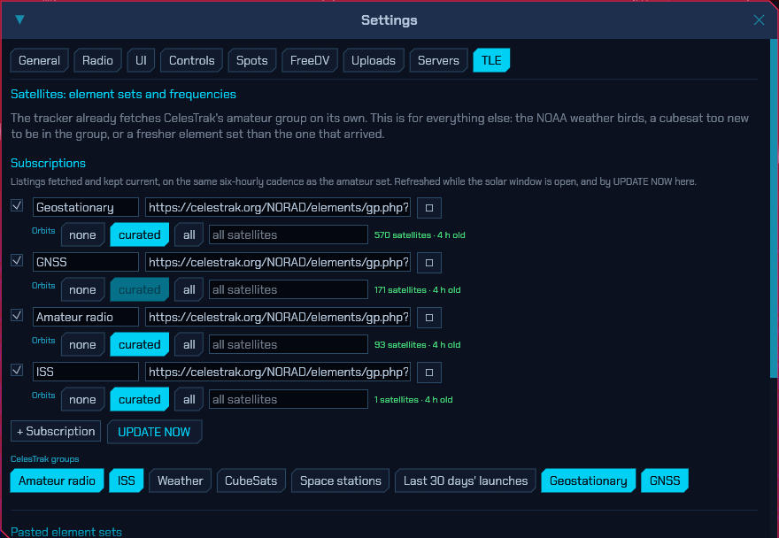
A two-line element set is only good for a few days: SGP4 accuracy decays quickly, and sdroxide refuses to propagate elements more than a fortnight past their epoch at all. So anything you mean to keep tracking wants a subscription — a URL serving an element-set listing, refetched on the same six-hourly cadence as the amateur set.
Each row has:
- a tick to track it or park it,
- a name (yours, for the row — the satellite names come from the listing),
- the URL, which must be
https://, -
Orbits — which satellites in the listing get an orbit ring and a label. Three positions, because there are three useful answers:
none Plain dots, visible only under ALL SATS. It really does mean none: the curated few are not exempt.curated Rings and labels only for the satellites in sdroxide’s own curated list — QO-100, the ISS, AO-7, FO-29, SO-50, AO-73, JO-97, RS-44, XW-3 and IO-117. all Everything in the listing. A whole group wants curated: ninety rings at once is unreadable, and none at all leaves ninety anonymous dots. A short listing like the ISS wants all.
That curated list is ten amateur satellites, so for a weather, GNSS or launch-window listing the middle position would behave exactly like none. It is greyed out on those once a fetch has shown the listing contains none of them — the position is not hidden, so you can see why it is unavailable.
- a filter — catalogue numbers to keep, comma separated. Empty tracks everything the listing carries. This is what turns CelesTrak’s fifty-satellite weather group into just the three NOAA APT birds.
The status beside each row is what the last fetch actually did: how many satellites it yielded and how old the listing is, or why it failed.
The CelesTrak groups buttons below add the common listings in one click. A lit button means you are already subscribed:
| button | What it is |
|---|---|
| Amateur radio | Every amateur satellite. On by default — this is what the tracker used to fetch unconditionally. |
| ISS | The ISS on its own, from its own element set. On by default: fresher than the copy inside the amateur group, and it keeps working if you unsubscribe from that. |
| Weather | The NOAA APT and Meteor LRPT birds on 137 MHz |
| CubeSats | Everything cubesat-sized, including amateur payloads too new for the amateur group |
| Space stations | The ISS, Tiangong and the vehicles docked with them |
| Last 30 days’ launches | Where a brand-new amateur satellite turns up first |
| Geostationary | The geostationary belt, QO-100 among it |
| GNSS | GPS, Galileo, GLONASS and BeiDou |
The two default ones are added the first time this version runs and then left alone: unsubscribing sticks, and if you have already customised one — renamed it, turned its orbit rings on — your version is kept rather than replaced.
Subscribing to a group does not put ninety orbit rings on the globe: both
default subscriptions arrive on the Orbits setting that suits them, so the
amateur group shows the curated few with rings and labels and everything else as
dots behind ALL SATS — exactly as it behaved when it was built in.
Subscriptions refresh while the 3D view is open, which is the same rule the rest of that window’s network activity follows (7). UPDATE NOW fetches them all immediately without opening it. Fetched listings are cached on disk, so they survive a restart and keep working offline.
6.9.2 Pasted element sets

For a one-off, paste the two- or three-line set straight into the box and press + Add pasted. Both forms are understood, several at once are fine, and pasting a set for a satellite already listed refreshes that entry rather than adding a second one.
Each row shows its catalogue number and how old the elements are — green while they are fresh, amber past three days, red once they are too stale to propagate. Press ✎ to see and correct the two lines (in a monospace font, because the format is column-addressed and a misaligned paste is otherwise invisible). A malformed entry says what is wrong with it instead of quietly never appearing in the sky.
Pasted satellites are always drawn with their orbit ring and label: typing a TLE in by hand is a clear enough statement of interest. They also override a subscribed element set for the same satellite, so this is how you put a fresher ISS TLE in front of the one CelesTrak served this morning.
6.9.3 Frequencies

These are the rows the pass table shows underneath a pass (7). Give a catalogue number and press + Satellite: if the built-in table knows it, the entry starts as a copy of it, so correcting one frequency does not mean retyping the beacon and the transponder as well.
Each link is a row: what it is, the downlink, the uplink, the mode, and a note
for anything you have to know before keying up. A frequency is either one number
(145.800) or a transponder passband written 145.950-145.970. Leave a
direction blank for a beacon.
An entry here replaces the built-in one for that catalogue number outright rather than merging with it — which is why a new one starts from a copy. Delete every link in an entry and it disappears, and the built-in table shows through again.
6.11 T/R switch: protecting the receiver on transmit
An SDR sharing an antenna system with a transmitter has to be disconnected before the transmit RF appears. A receiver that is fine on a microvolt does not survive a hundred watts of it.
The usual answer is a relay: a coax relay that disconnects the SDR and grounds its input, an outboard T/R switch, or the receive-antenna port on an amplifier. This tab drives one — and sequences an amplifier or a second relay with it — so the contacts always close before your transmitter comes up and open after it has stopped.
Read 6.11.5 before relying on this feature.
6.11.1 What it can drive
| Hardware | What it is |
|---|---|
| USB relay board (serial) | The cheap boards sold everywhere: LCUS-1/2/4/8 (a CH340 in front of a microcontroller), KMtronic, and Numato Lab. They appear as a serial port; pick the port and the make. |
| Serial RTS/DTR line | A contact closure on any USB-serial adapter, a DigiRig, or a home-made opto-isolator. What every outboard sequencer with a PTT input wants — W6PQL, DX Engineering, Array Solutions. Contact 1 is RTS, contact 2 is DTR. |
| USB relay board (HID) | The “free-driver USB control switch” family, sold under MagiDeal and a dozen other names, 1 to 8 channels. No driver on any platform. |
| CM108/CM119 sound-card GPIO | The pins on a cheap USB “rig interface” — DRA boards, the RB-USB RIM, the AIOC. Pin 3, the one every design brings out. The audio the card is carrying for your radio is on a different interface and is not disturbed. |
| Linux GPIO line | A Raspberry Pi header, or any board with a /dev/gpiochip*. |
| External command | Runs a program on key-down and another on key-up. For everything with a command-line tool and no protocol worth building in: Denkovi’s boards, microHAM, usbrelay, a script of your own. |
On Linux the two USB kinds need permissions the distribution does not grant. Install the packaged rule and replug:
sudo cp packaging/linux/60-sdroxide-relay.rules /usr/lib/udev/rules.d/
sudo udevadm control --reload
Serial relay boards need nothing from that file — they are serial ports, so add
yourself to dialout as you would for a CAT cable.
Every packaged rule — this one and every receiver’s — grants access two ways: an
ACL for whoever is logged in at the seat (TAG+="uaccess"), and a group for
everyone else. The ACL grants nothing where there is no seat to be logged in at
— WSL2, a headless machine over ssh, a container, or sdroxide running as a
systemd service — and the device stays root-owned with nothing on screen saying
why. In that case join the group the rule names (plugdev for USB receivers and
HID relay boards, gpio for GPIO lines, dialout for serial), then log out and
back in:
sudo groupadd -f plugdev && sudo usermod -aG plugdev $USER
6.11.2 Contacts and the sequencer
Each row in the Contacts table is one switched contact:
- No. — which contact on the board, numbered as its silkscreen numbers them, from 1.
- GPIO — shown only for a Linux GPIO line: the line’s offset on the chip, which on a Raspberry Pi is the BCM number and not the physical pin number.
- Name — yours. It appears in the status line and the log, so “IC-7300 antenna” beats “channel 1”.
- Job — grounding the SDR antenna, keying an amplifier or T/R relay, auxiliary, or a band decoder (6.11.7). For the first three it only chooses the default timings and what the log calls it; a band decoder follows the band table as well as the over.
- TX closes — whether transmitting energises the coil. This is a wiring decision, not a preference; see 6.11.4.
- Lead — how long before RF the contact closes.
- Hold — how long after RF stops it opens. Zero is a real answer, and the right one for an amplifier’s key line.
- TEST — closes that contact for half a second so you can hear the relay and check the wiring with the transmitter cold. Refused while anything is on the air.
The order is the timings. There is no ordering column because there does not need to be one: at key-down every contact closes at its own lead before the RF, so the longest lead goes first; at key-up every contact opens at its own hold after the RF, so the shortest hold goes first. Give the antenna relay the longer lead and the longer hold and the amplifier the shorter of each, and you have a sequencer:
  antenna relay   ────────█████████████████████████████──────
  amplifier key   ─────────────█████████████████──────────────
  RF              ──────────────████████████████─────────────
                        ↑     ↑                ↑     ↑
                   antenna  amp key         amp off  antenna
                   throws                            returns
The panel spells the resulting sequence out in one line under the table, so you can see what you have bought without working it out.
Choosing a Job fills both in with numbers that sequence correctly: 10 ms and 20 ms for the antenna, 5 ms and 0 for an amplifier. A small coax relay throws in 5 to 15 ms. Longer than it needs to be costs you something real: transmit waits for the longest lead, so a large value is an audible gap at the end of the receive audio and a delay between your thumb and your own transmitter. Anything over 250 ms is ignored. The hold is free by comparison — letting the antenna back a moment late costs nothing, and letting it back early costs a front end — so when in doubt, lengthen the hold rather than the lead.
If it will not answer decides what happens when the hardware stops responding. Refuse to transmit is the default, and it behaves like the SWR guard: the over is refused with a notice rather than sent into an unprotected receiver. Transmit anyway, warn is for a station running a few watts into a preamp bypass, where a loose USB cable ending a contest is the worse outcome.
6.11.3 The transmit sense input
When you key a transceiver at the radio — its own microphone button, a foot switch, VOX, or its keyer — sdroxide does not know until it next asks over CAT. That question rides the meter poll, so the answer arrives a few hundred milliseconds into the over, and the relay throws then.
The fix is a wire. Bring the rig’s SEND / PTT / accessory key line, through an opto-isolator, into a handshake input on the same serial port that drives the relay, and set Line to CTS, DSR or DCD. sdroxide watches it every five milliseconds, so the over is seen almost at once — and not only by the relay: the meter switches to transmit, and the interlock that stops sdroxide keying on top of you starts working, at the same speed.
Most opto-isolated interfaces pull the line down when the rig keys, so leave Transmitting is a high line off unless yours does the opposite. On a station with more than one radio, Belongs to radio says which tab the sensed transceiver is.
6.11.4 Wire it so that a dead relay is the safe one
This is the only fail-safe that survives sdroxide not running, the USB cable being pulled, or the computer being off — and no setting can substitute for it.
Choose TX closes so that the de-energised contact is the state you want when nothing is running:
- De-energised = SDR grounded. Protective. The coil is held energised the whole time you are receiving, and a dead relay leaves the SDR deaf — annoying, and safe.
- De-energised = SDR connected. Convenient. A dead relay plus one transmission is a dead front end.
With a real amplifier behind it, take the first.
6.11.5 What this cannot do
It cannot protect from transmissions initiated at the radio itself.
Keying from sdroxide is the arrangement this was designed for: the contacts lead the RF by construction, because the transmit path waits for them. Set your rig’s PTT method on the Radio tab and press PTT here rather than on the microphone, and the guarantee holds every time.
A transmission initiated at the radio is different. Without the sense input above, sdroxide learns of it a few hundred milliseconds late; with the sense input, in a few milliseconds — but even then the relay itself still has to throw, after the RF has started. No program on a computer can make that zero.
For a receiver genuinely worth protecting, use an RF-sensed hardware T/R switch as well. It costs a fraction of the SDR and it does not depend on a computer being awake. What this tab gives you is sequencing, an amplifier interlock, and protection on every over sdroxide keys — which on a digital-modes or remote station is all of them.
An HPSDR operator already has a hardware-timed version of the same thing in the J16 open-collector outputs; see 6.2.3.
6.11.6 If it does not click
- The device is not in the list. On Linux, install the udev rule above and
replug.
cargo run -p sdroxide-relay --example relay -- --list --allprints every HID device the machine can see, which separates “not permitted” from “not recognised”. - A CM108 card that is listed and does nothing. Several clones carry a genuine C-Media id and ignore the GPIO report entirely. Nothing but listening for the click tells them apart.
- The relay clicks and nothing switches. The board’s contacts are the other way round: change TX closes, and re-read 6.11.4 before you settle on which way.
- A Numato board operating the wrong relay. It numbers relays from zero on the wire; sdroxide converts, so use the number on the silkscreen.
- Reporting a fault. Settings → Radio → the diagnostic report includes what the switch was told and what it answered. On these boards there is no other record of anything, anywhere.
6.11.7 Band decoder outputs
A contact’s Job can be Band decoder (filter / transverter) instead of grounding the antenna or keying an amplifier — for a station with per-band external hardware in front of the radio: a bank of band-pass filters on receive, low-pass filters on transmit, or a transverter selector, on a PlutoSDR, a LibreSDR, or anything else that has no band-aware output of its own (issue #442). The same idea as an HPSDR board’s open-collector band code (6.2.3), generalised to whatever this relay hardware actually is — a USB relay board (serial or HID), a GPIO header, or the two RTS/DTR lines. Not a CM108 pin or an external command: each of those is a single on/off for every contact, so a band’s RX word would key it for as long as you were receiving there, and the settings refuse the combination.
A retune moves a band-decoder contact the instant the band changes. Keying is different: going from a band’s RX word to its TX word is an on-air edge like any other, so a band-decoder contact has a Lead and a Hold of its own and is sequenced exactly like the antenna relay and the amplifier — a transmit-only low-pass filter is in circuit its lead before RF, and out only its hold after. Its lead counts toward how long transmit waits. That is true even of a contact whose RX and TX bits agree, because a split across bands changes every one of them at key-down. It shares the same board as any ordinary on-air-driven contact without disturbing them.
Once at least one contact has the role, a Band decoder outputs table
appears below the sequencer. One row per band, two control words each — RX
and TX — read the same way the HPSDR OC table is: bit 0 is contact 1, bit 1
contact 2, and so on up to contact 32. Give RX and TX the same value for a
filter that does not care which way the RF is going; give them different ones
for a receive-only preamp bypass or a transmit-only LPF bank that must not be
in circuit on receive. A band left at 0x00 asserts nothing. The Outputs
asserted column names the contacts a word actually closes, so you never have
to work the bit pattern out by hand.
The RX word is the receive dial’s band, on the primary radio — the bank belongs to the station. The TX word is the transmit dial’s band of whichever radio keyed, so on a multi-radio station the filters follow the radio that is actually transmitting, and a split operator’s follow where the RF is going. Retuning the transmitter during an over does not move a filter that is carrying RF: the new band is taken after that over’s hold, or at the next key-down. Behind a transverter table that is the true dial, the same one the HPSDR OC decoder follows: the filters, relays and transverter this switches belong to the band on the air, not to the intermediate frequency underneath it.
6.12 Profiles: saved station setups
A profile is a named snapshot you take on purpose — contest, DX, nets, a band plan — of how the station is set up, and Apply puts all of it back in one click. Type a name on the Profiles tab and press Save; the list below has Apply and ✕ (delete) for each saved one. Saving under a name that already exists replaces it (names are matched without regard to case).
What a profile holds:
- The dials — both VFOs, which one is in use, and the mode on each. A profile saved on VFO B comes back on VFO B, and a radio with a pair of VFOs of its own is told which one before it is retuned.
- The receiver and transmitter levels — AF volume and mute, RF gain, AGC, squelch, noise reduction, binaural, drive, tune drive, mic gain, CESSB and the transmit EQ, and the repeater settings.
- The antennas and gain stages, including the antenna kept per band — applied the same way a restart restores them, so a port or a stage the radio does not have is skipped rather than refused.
- The digital identity and messages — callsign, grid, the message templates and CW message buttons, and the rest of the digital-mode settings. Three things stay as the station has them, because they follow the band and the mode rather than a way of working: the transmit audio offset per band, the transmit level per mode, and the contest serial number.
- The band stacks — the frequency, mode and filter each band button brings back (2.4), replaced wholesale, so the bands recall this setup’s own frequencies.
What it deliberately leaves out is the hardware: the interface, the sound devices and the converters are properties of a radio, not of a way of working it, so a profile follows you across the rig you always sit at rather than dragging yesterday’s sound card behind it. Applying one retunes rather than reopens anything.
Apply is refused while the station is on the air — by any route, including a rig keyed at its own microphone — since it moves the dial and the transmit setup under the over. The callsign, messages and band stacks are station-wide, so on a station with several radios applying a profile on one changes them for all of them, as editing them does.
Profiles are kept in profiles.json on the machine the radio engine runs on
(§13), shared by every radio of the station, and a
remote or browser client sees, saves and applies the same list.
6.13 Audio: your sound, the radio’s, and recordings
Sound used to be in four places under four names: your speakers and microphone on General, the rig’s sound card on Radio — and differently again on each interface — speech on UI and the alert tones on Alerts. None of that was wrong; it just could not be found as one thing. This page is one thing, and the organising idea is whose audio it is rather than which file it is saved in.
Your audio — the speakers you listen on and the microphone your voice goes out through:
- Speakers — where receive audio is played.
- Channels — which speaker channel(s) the audio reaches. Left or right silences the other, for hearing on one side only.
- Microphone — what carries your voice out when the rig is keyed by sound (MCW) or by VOX. If your rig keys itself from CAT instead, the microphone is not used for transmit at all and this row changes nothing.
These belong to this machine and to you, not to any radio, so they are the same
whichever radio you are working. Both device rows default to System default
and can be changed live. In config.toml they are audio_output,
audio_routing and audio_input.
In a browser the page says so. A browser tab has no device list to offer — the page asks your browser for the speakers and the microphone, and the choices live in the browser’s own site settings. The radio’s sound card, further down this page, still applies.
This radio’s audio — the sound card between this radio and this computer:
- From the radio — what your rig sends out: a USB sound output, or a receiver’s headphone socket into a sound card’s line input. Everything on the panadapter and in the decoders arrives here.
- To the radio — what the rig listens to for your voice, and also how the program keys a rig by sound. Leave it empty and the rig’s own microphone is used, if it has one.
- Receive audio gain — extra gain on everything this radio sends to the speakers. Leave it at 0 dB unless the radio is quiet at full volume.
- Stream the audio out — a
host:portthat receives the audio over UDP, so another program can use it.
A receive-only radio (the ATS Mini) is offered no transmit row, and an SDR is offered no sound card at all: neither has one, and a row that cannot do the thing is worse than no row.
These are per radio, and they always were. Two rigs running at once use two sound cards at once, so these rows edit the radio you opened Settings from — the one on the tab you opened it from. They moved off the General page in 1.6.9 for that reason (issue #474) and are here now because this page gathers sound in one place;
radio.jsonnever changed.
You can type a device name. Every picker is a list and a text field. The list is what the host’s audio API enumerates, and a sound server can hold devices it does not report — a PipeWire node is the case this fork knows about, and enumerating those is the open half of the Bluetooth microphone work. A picker that can only be pointed at leaves you with no way to name a device you can hear. Type the exact name the sound server uses; an empty field is the system default.
Recording — the folder the MP3 recordings, the scheduled recordings and the
raw I/Q captures are written to, with CHOOSE… to pick another and DEFAULT
to go back to the music folder (<Music>/sdroxide, or the config directory’s
recordings where the system exposes no music folder). It is a path on the
machine the radio is attached to, so it is shown only where the engine is in this
process. In config.toml it is recordings_dir.
The rest of the recording controls are not here on purpose: Quick clip, Stop after and Auto-record answer a question about this session, so they live on the REC chip where you press them rather than becoming a setting you have to remember you changed.
7. Solar system 3D view
The ☀ 3D button in the Display module opens the solar system in three dimensions — the Sun, the Earth and the Moon, the other seven planets and eighteen of their moons — with live solar imagery, sunspot regions and coronal-mass-ejection trajectories. This enables operators to see if anything is on its way here, and when it will arrive.
In the native app this is a second window. In the web client it is a second browser tab, with the same controls, the same layers and the same QSO visualisation; there, the data below is fetched by the server and relayed to your browser rather than fetched by the browser itself. Several people may watch the map at once — it controls nothing, so it does not take the single control connection — but they share one feed, so changing the SDO channel changes it for everyone watching.
The window itself. There is one 3D window, and it belongs to the program rather than to a radio tab. Switching to another radio leaves it up; opening the 3D on another radio moves it there and closes the previous one, so a session cannot accumulate them. Where you leave it — its size, and its position where the platform reports one — is remembered in this screen’s settings and put back when it is opened again, fitted so it never comes up off the screen. On Wayland a client is not told where its windows are, so only the size is restored and the compositor chooses the place; on a tiling compositor the same applies, and the window keeps the tile you gave it precisely because a tab switch never closes and reopens it.
If the browser crashes. This view is the app’s heaviest graphics consumer — a depth buffer, multisampling and a few dozen draws a frame — and browser WebGPU implementations vary in how well they take it. Firefox on Linux has been seen to abort the whole browser process with this page open. Adding
&gfx=webglto the URL pins the page to WebGL2, which draws the same scene and only gives up multisampling and a little depth precision:http://<host>:4950/?view=solar&gfx=webgl.&gfx=webgpuforces the other way. Without either, the browser’s own preference is used.
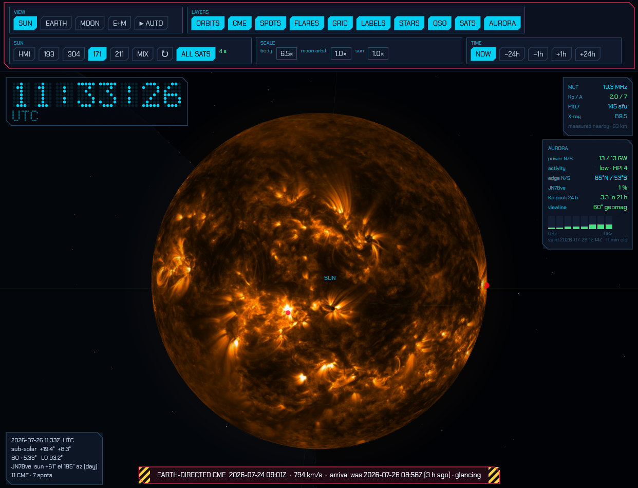
The Earth carries a higher-resolution version of the same Natural Earth data as the FT8 world map — coastlines, international borders and rivers — lit by the real Sun with a soft terminator. Your QTH is the green ring and the yellow dot is the point the Sun is directly overhead; both appear once you zoom in far enough for a point on the surface to mean anything.
On the night side the cities light up, from Natural Earth’s built-up urban areas: the Ruhr is a sprawl, the Nile is a thread through the desert and the Sahara around it is empty, which is what the photographs from orbit show. It is the one place on this globe where the map stops being a line drawing, and it can afford to be because it is not invented.
The coastlines and borders keep a faint glow of their own on the night side, fading in across the terminator the way city lights do. It is deliberately subtle — the terminator is still the most obvious thing on the globe — but it means the dark hemisphere stays a map rather than a slab, which matters because almost everything worth looking at happens there: the far end of a grey-line QSO, the auroral oval, a satellite footprint crossing at 3 a.m.
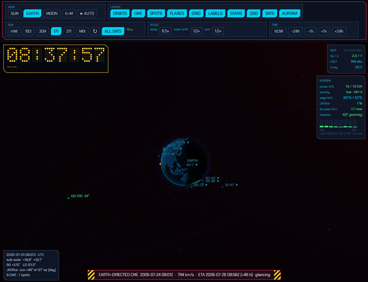
7.1 Navigating: the camera, targets and the auto tour
Mouse:
| Action | Effect |
|---|---|
| Drag | Rotate around the focused body |
| Scroll | Zoom in and out |
| Click a body or its label | Make it the camera’s target |
Any mouse input cancels AUTO.
Target — the ◎ button names what the camera pivots around and opens a
picker with everything in the system: SUN, EARTH, MOON and E+M (the
Earth–Moon midpoint), then a row per planet with its own moons beside it.
Choosing a target pulls the camera in to frame it. You can also simply click a
planet, a moon or its name in the view — hovering marks the body with a reticle
first, so there is no guessing about what a click will grab. ▶ AUTO flies a
continuous camera path through various framed viewpoints to make for an informative
and visually pleasing display that you could have on a main monitor or projector.
While you are working a station, AUTO leaves the loop and flies down to the
contact instead, holding it for as long as the QSO lasts — the readout calls it
QSO PATH. The shot is centred on your QTH, the station you are working and the
arc between them, from off to one side of the path and at a shallow angle, so
the horizon curves across the frame and the arc’s rise off the surface is plain
rather than flattened into a line by an overhead view. It frames itself to the
path: a neighbouring country is a low pass over the horizon, an antipodal
contact pulls back until both ends and the whole arc are in the picture. When
the QSO ends the camera rejoins the tour at whichever viewpoint is nearest.
Switching the QSO layer off leaves AUTO on its normal loop.
7.2 The layers
Layers — ORBITS (orbital paths, sampled from the real ephemeris, so they
are the true eccentric orbits), CLOUDS, PLANETS, CME, SUN OBS, LABELS,
SMALL BODIES, QSO, SATS, AURORA, PROP and AWARDS. All but PROP and
AWARDS are on to begin with — those two each paint the whole planet (one with a
marker on all three hundred-odd DXCC entities, the other with a wash of colour),
so they wait until you ask for them. Switching either on stands the other down,
because two full-globe washes at once is neither.
SUN OBS is solar observations on the Sun’s disk: the sunspot active regions
and the flare source locations, which used to be two buttons and are one idea.
The name also settles a collision — everywhere else in this manual, SPOTS
means the DX cluster.
The star field and the heliographic graticule (the solar rotation axis, equator and parallels) have no buttons: they are the backdrop and the coordinate frame everything else is read against, and are always drawn.
7.3 The planets, moons and small bodies
The PLANETS layer adds the rest of the solar system: the seven other planets, eighteen major moons, and Saturn’s and Uranus’s rings. Names are shown for every planet however small it is on screen — from anywhere in the inner system Neptune is a fraction of a pixel, and the label is the only thing that makes it findable — and a body’s own name disappears once you have flown close enough to it that the name would be stamped across the picture. A planet’s moons are named once the planet itself is big enough on screen for the names not to pile up.
Where the numbers come from, and how good they are:
| Source | Accuracy | |
|---|---|---|
| Planet positions | JPL’s Keplerian element set for 1800–2050 | Measured against JPL Horizons over 2015–2045: better than 0.02° for the inner planets, 0.12° for Saturn |
| Orientations | IAU/WGCCRE rotational elements | Poles and rotation rates; the small periodic terms are dropped |
| Moon orbits | Circular orbits fitted to JPL Horizons | Under 1° of orbital phase for most, up to 4° for Titan and Iapetus, whose real orbits a circle cannot express |
The Moon, Jupiter and Saturn are drawn from published spacecraft maps — LRO’s lunar albedo mosaic and Cassini’s global maps of the two giants. The other bodies are procedural: Mars gets its polar caps and dark albedo markings, Io its sulphur yellows, Iapetus its black leading hemisphere. Radii are exaggerated by the body scale like the Earth’s, but capped so that no planet ever outgrows the Sun; each planet’s moons are scaled by the same factor as the planet, so a moon at six planet radii is drawn at six planet radii.
The dwarf planets, asteroids and comets ride on the same PLANETS layer.
Forty bodies: Pluto, Ceres, Eris, Haumea and Makemake; twenty asteroids; and
fifteen periodic comets.
They are there because the next fifty years turn on them, and that is a query
rather than an opinion. tools/fit_smallbodies.py asks JPL’s close-approach
database for everything that passes inside 0.02 AU of the Earth between now and
2076 and is big enough to be worth naming — which is how Apophis, 2001 WN5 and
1999 AN10 got in — and adds the bodies anyone would expect to find: the dwarf
planets, the large main-belt asteroids, the mission targets (Bennu, Ryugu,
Itokawa, Didymos, Psyche, the two Lucy Trojans), and every periodic comet with a
perihelion inside the window. Swift-Tuttle is absent for that last reason: the
Perseids’ parent does not come back until 2126.
Point the camera at one and the info card gives its distance, its perihelion and aphelion, the length of its year, and one line on why it is in the table — the date and distance of the close approach, straight out of JPL’s database, or the spacecraft that went there.
Finding one is what the box under the clock is for. It searches the small
bodies and the satellites together, on name, catalogue number or designation:
apophis, 99942, 1P, 2024 YR4. A match is drawn with its orbit and its
name whether or not it otherwise would be, and ↵ on a single match flies the
camera to it. The asteroids have no layer button of their own on purpose — a
button answers “show me all thirty-five of these”, which is not a question
anyone has; the question people have is where is Apophis, and that is a search
box. The SMALL BODIES button is a different thing: it governs their names,
because thirty-five designations at once bury the planets. Whatever it is set
to, the body the camera is on and anything the search has matched stay named.
Comets grow tails, and the tails are geometry rather than decoration:
- The ion tail is CO⁺ fluorescing at 420 nm — blue, and not reflected sunlight at all. It is swept by the solar wind, so it points away from the Sun rather than back along the orbit, and it is drawn dead straight, narrow, and broken into the rays and travelling knots the plasma makes as the field it is frozen into varies. It does not point exactly anti-sunward: the comet meets the 400 km/s wind while crossing it at its own orbital speed, so the tail lies along the difference and lags the radial line by a few degrees. That angle is what makes a photograph of a comet look the way it does.
- The dust tail is grains reflecting sunlight — warm, broader, smoother, and curved, because the grains are far too heavy for the wind to sweep and keep the orbital velocity they were released with while radiation pressure eases them outwards.
- The coma is the head: a hundred thousand kilometres of gas, green from diatomic carbon, which is the part of a comet that is actually bright.
All of it switches on and off with the comet’s distance from the Sun. Water ice stops sublimating past about 3 AU, so a comet spends most of its orbit as a bare dot and lights up for the months around perihelion; the tails grow as the inverse square of the distance and with the cube root of the nucleus radius. Phaethon is the exception that shows the model is doing something: it is a rock, not a comet, and gets a short dust tail and no ion tail at all, inside a fifth of an AU of the Sun where its own surface is being cooked apart.
Use the Time module’s ±1 mo steps to watch it happen — Encke returns every
3.3 years, Tempel-Tuttle in 2031, Halley in 2061.
Where the numbers come from, and how good they are:
| Source | Accuracy | |
|---|---|---|
| Small-body positions | A chain of Keplerian arcs fitted to JPL Horizons across 2026–2076 | Measured against Horizons: inside 0.16° for every body but Apophis, whose 2029 Earth encounter changes its orbit and leaves it at 0.66° worst case, 0.03° typical |
| Which bodies | JPL’s close-approach database, plus the dwarf planets, large asteroids and mission targets | The close-approach dates and distances quoted in the info card are JPL’s, not this model’s |
| Tail lengths | A visual model, stated as one | Scaled so Halley at its 2061 perihelion draws the tail Halley actually had; the directions are physics |
Outside 2026–2076 the arcs simply run on, which is a two-body extrapolation of a perturbed orbit and decays quickly. Scrub the clock past either end and the info card says so rather than letting the body sit there looking authoritative.
7.4 Clouds
The CLOUDS layer puts the weather on the globe, live, from NOAA/NESDIS’s Global Mosaic of Geostationary Satellite Imagery — GOES-East and GOES-West, both Meteosats and Himawari, stitched into one picture of the planet every hour.
Like the aurora it is drawn as a depth of air rather than as a picture stuck on a sphere, and for the same reason: that is what it is. What makes that possible is the infrared channel. Brightness in the infrared is cloud-top temperature, and temperature is altitude — so the renderer is handed a height field taken from measurement, and a thunderhead stands fifteen kilometres tall over the stratus beside it because it really does. The Sun lights the tops and they shade their own undersides, which is what makes a deck read as three-dimensional rather than as fog, and the limb shows the deck standing off the surface because a grazing line of sight crosses a great deal more of it.
Two channels are fetched. Infrared is the backbone and works in the dark. Visible is a correction on the sunlit half only: low warm cloud is nearly invisible to infrared — the top of a marine stratus deck is within a few kelvin of the sea under it — and obvious in visible light, so where the Sun is up that channel fills in what the first cannot see.
What is real and what is not. The cloud field is measured. The lightning is simulated — and the readout along the bottom of the window says so, because a globe that flickers with plausible-looking strikes must not be read as showing strikes. What comes from the data is where the thunderstorms are, how large, how tall, and how often each should flash: cold-top area is the oldest satellite proxy there is for flash rate and a good one. What is invented is which millisecond a given stroke fires. No free worldwide feed of individual strikes exists to use instead. The flashes light the cloud from inside rather than being drawn as marks on it, so an anvil goes bright from below.
Four honest limits, all of them stated in the readout or visible in the picture:
- Nothing is known above about 73°. A ring of geostationary satellites cannot see the poles, so the layer fades out towards them rather than guessing. The aurora owns those latitudes anyway.
- The picture is an hour or more old. The mosaics are published hourly and run about an hour and a quarter behind the clock. The readout gives the hour the picture is of, never the moment it was fetched.
- Cloud-top height is a fit, not a retrieval. The mosaic is a rendered image rather than a calibrated field, so the brightness-to-temperature ramp is a fit to the standard infrared enhancement. The shapes are exactly what the satellites saw; the heights are the right heights to within a kilometre or two.
- A cloud field is a difference. Cloud is measured as brightness above a locally estimated clear-sky background — which is what stops the cold winter hemisphere and the polar night being read as an overcast, and what makes the deserts come out clear. The cost is at the other end: an overcast broader than the window used to estimate it sets its own background and reads thinner than it is.
The vertical scale is exaggerated about six times. Eighteen kilometres on a six-thousand-kilometre planet is a quarter of one per cent of the radius, and a hairline cannot be volumetric; six times over is enough for a storm to stand up out of the deck and shallow enough that nobody would mistake the result for a mountain range. Altitudes are fractions of the radius the globe is drawn at, so the deck stays glued to the surface at any setting of the body scale.
Cloud rendering on the UI settings tab (6.3) chooses how the deck is drawn. Layered stacks slices through the troposphere and is the cheap option. Volumetric walks a ray through it instead, so the Sun casts the cloud tops onto the deck below and a flash glows out through the storm making it rather than only brightening its outside — at several times the cost per pixel. Both draw the same weather.
7.5 The aurora
The AURORA layer puts the auroral oval on the globe, live, from NOAA’s OVATION model — a 1°×1° grid of the probability of seeing aurora, issued every few minutes and valid about forty minutes ahead.
It is drawn as a stack of glowing shells at the altitudes the atmosphere actually radiates at, not as a texture painted on the surface, and everything about how it looks falls out of that. The colour changes with height because the emission lines do: green oxygen at 557.7 nm around 110 km, the forbidden red line at 630 nm hundreds of kilometres above it, and a violet nitrogen fringe underneath when the precipitation is hard — which is why a quiet oval is green and a storm goes crimson at the top. The limb is far brighter than the disk, because a grazing line of sight crosses a great deal more of every shell, giving the thin bright ribbon on the horizon that is the most recognisable thing about aurora seen from orbit. The fine structure runs in arcs along the oval and in rays through the stack, because auroral precipitation is field-aligned. And because the emission is only drowned out by daylight rather than stopped by it, the sunlit half of the oval fades to a floor rather than to nothing — you can still see where it is.
The structure is shaping, not invention: it multiplies what the grid says and can never put aurora where NOAA has none. The green contour on the surface is the honest boundary — the equatorward edge of the 10 % line, straight off the grid, drawn to be compared against your own latitude. It bulges towards the equator on the night side and over the magnetic poles, which is where it really does; the southern oval reaches much lower geographic latitudes than the northern one for exactly that reason.
Aurora panel — under the propagation numbers on the right:
| Row | What it is |
|---|---|
power N/S |
Gigawatts being deposited in each auroral zone. This is the number that says how big the event is. |
activity |
The same figure as NOAA’s Hemispheric Power Index, 1–10, with a word for it. Yellow from HPI 6, pink from 8. |
edge N/S |
How far towards the equator the 10 % contour reaches in each hemisphere, read off the grid. |
| your grid square | The probability of visible aurora directly over your QTH. Green when there is anything at all, yellow past 10 %, pink past 25 %. |
Kp peak 24 h |
The worst three-hour bin still ahead of you in NOAA’s planetary K forecast, and how far away it is. |
viewline |
Roughly how far towards the equator that Kp puts the aurora, as a geomagnetic latitude. A rule of thumb — see below. |
Under the rows is the planetary K trend: one bar per three-hour bin, the
observed history behind you flowing into the forecast ahead, so the shape of the
last day and the shape of the next are one picture and “it picks up after
midnight” reads at a glance. The measured bars are solid and the predicted ones
a wash, with the boundary between them marked, because a measurement and a
prediction must never be read as the same thing; the foot of the chart says
observed | forecast and the ends carry their UTC hour. Green is quiet, yellow
worth watching, pink a storm. The footer says what the picture is valid for
and how old the fetch is — never what time it is now, because the grid is a
forecast for about forty minutes ahead and may itself be half an hour old.
The viewline row is the one number here that is not measured. It is a
straight-line fit to SWPC’s published table (66.5° at Kp 0, falling about 2° per
unit of Kp) and it says nothing about cloud, moonlight or how dark your sky is;
geomagnetic latitude is also several degrees from geographic at most longitudes.
The oval on the globe needs none of those caveats, so prefer it when the two
seem to disagree.
7.6 Satellites
The SATS layer puts amateur-radio satellites in orbit around the globe, live,
propagated with SGP4 from CelesTrak element sets. Ten popular ones are drawn by
default with their orbit rings — QO-100, the ISS, AO-7, FO-29, SO-50, AO-73,
JO-97, RS-44, XW-3 and IO-117. Geostationary orbits are green, low ones cyan.
ALL SATS in the Sun module adds every satellite in the subscribed listings as
a plain dot; the orbit rings stay on the curated few, because ninety rings at
once is unreadable.
Which satellites arrive at all is set in the TLE settings tab (6.10) — the amateur group and the ISS are subscribed by default, and you can add the weather birds, the cubesats or your own element sets beside them. A set you paste in there is always drawn with its ring and label, and overrides a fetched one for the same satellite. Those fetches happen while this window is open, like every other fetch it makes.
With LABELS on, each of the curated satellites is named with its elevation
from your QTH right now — a number means it is above your horizon and
workable, ▼ means it is not.
Finding one by name. The search box under the clock takes a designator or a
catalogue number — AO-73, o-7, 25544 — and matches are pulled out of the
crowd in yellow, with their orbit ring and their name, whether or not they were
being drawn a moment ago. That is the point of it: a satellite outside the
curated set has no label at all until ALL SATS is on, and then there are
ninety unlabelled dots. Matching is case-insensitive and on any part of the
name, so a partial designator is enough. The line underneath says how many of
the tracked satellites matched; Enter on a single match opens its pass
table, and ✕ clears the box. The same box finds the dwarf planets,
asteroids and comets — see the PLANETS layer above — and Enter on a single
body flies the camera to it instead. It appears whenever either the SATS or
the PLANETS layer is on, since those are the two populations it can find
anything in.
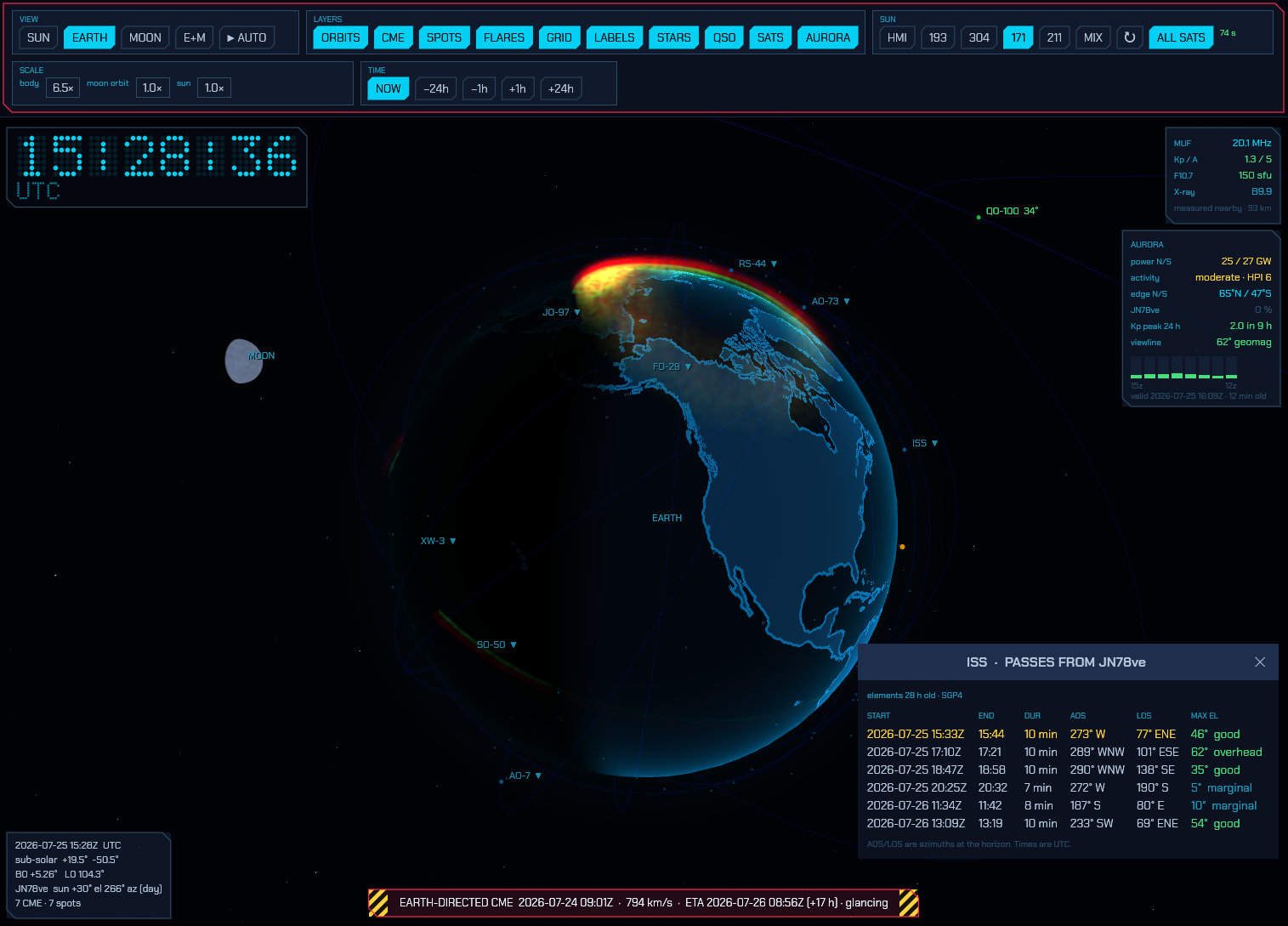
Click a satellite’s label for its pass table:
| Column | Meaning |
|---|---|
START / END |
Rise and set times, UTC |
DUR |
How long the pass lasts |
AOS / LOS |
Azimuth at the horizon on acquisition and loss — where to point, and where it ends up |
MAX EL |
Highest elevation reached, with a word for how good that makes the pass |
A pass already under way is shown in green, one starting within the hour in yellow. QO-100 is geostationary, so instead of a table it tells you the fixed azimuth and elevation to point at — it never sets. A satellite whose orbit never reaches your latitude says so rather than showing an empty table. Click the label again, or close the window, to dismiss it.
Predictions come from SGP4 on the current element set, and the window shows how old those elements are. A day-old TLE is good to a second or so on rise time; a week-old one is not, which is why the age is on display.
Below the pass table is the satellite’s frequency list — what to actually tune to once it comes over the horizon:
| Column | Meaning |
|---|---|
LINK |
What the link is: a linear transponder, an FM repeater, a beacon, a telemetry or APRS downlink |
DOWNLINK |
Where to listen, in MHz. A transponder shows its whole passband |
UPLINK |
Where to transmit, in MHz. — for a beacon, which only transmits |
MODE |
The emission: SSB/CW, FM, BPSK 1k2, DVB-S2, … |
Anything you have to know before keying up — a CTCSS tone, an inverting transponder, a bird that only runs to a schedule — is spelled out under the table and repeated as a tooltip on the link name. Remember that these are the nominal frequencies: Doppler moves a LEO downlink by several kilohertz across a pass, upwards on the way in and downwards on the way out. The LOCK ON button above the table hands the satellite to satellite mode, which corrects for exactly that — the locked bird is highlighted on the globe with a line drawn from your QTH to it, and with AUTO the camera frames the two of you through the pass.
The built-in list covers the satellites drawn by default plus a few more, and it is reference data transcribed from the AMSAT list rather than anything derived from the element set — transponders do get switched and schedules do change. Add your own or correct a wrong one in the TLE settings tab (6.10), where your entries override the built-in table. They belong to the station, so the browser’s 3D view shows them too — it is fed by the same engine — and a correction made at the shack machine is on screen in every open tab.
7.7 Your QSOs on the globe
The QSO layer puts your FT8/FT4/FT2 traffic on the globe. Every station decoded in the last two minutes is a white dot that fades as it ages — the same set the flat map in the FT8 panel shows, so the two never disagree. Behind them, every decode of the last hour is an arc from your QTH to the station that sent it, cyan when it is fresh and cooling to violet as it ages out of the trail, with a spark running the newest ones in the direction the signal travelled. That is the band’s shape over the last hour, drawn: which paths were open, and when they opened.
The station you are working is joined to your QTH by a heavy green beam with a ring on each end and a pulse running the path — outwards to them while you transmit, back to you the rest of the time — so the QSO in progress is unmistakable among an hour of traffic. Green is the globe’s colour for your own station: it is what the QTH ring under one end of the arc already wears. A decode you have clicked but not yet answered gets a thin yellow arc. All of them are true great circles lifted off the surface, bowing further out the longer the path: an antipodal contact springs well clear of the planet, which is the only way both ends stay visible at once on a sphere.
The contact card rides the top of that arc. It types itself out a line every half second as the contact runs, and carries what the QSO is:
| Row | What it says |
|---|---|
| heading | The station you are working. |
MODE |
The mode and the band — FT8 · 20M. |
PATH |
Great-circle distance and your initial bearing to them. |
TIME |
How long the contact has been running. |
SENT |
The report you sent them, which is their signal at you. |
RCVD |
The report they sent you. |
SIG |
Their signal at you in the most recent slot — the live number, which keeps moving after the reports are settled. |
GRID |
Their grid square, once they have sent one. |
DXCC |
The entity their callsign resolves to. |
Rows appear only when there is something to put in them, so a contact that has not got as far as exchanging reports simply shows a shorter card. It is pinned to the arc’s highest point in three dimensions rather than to a place on the screen, so it rides the arc as you turn the globe, with a leader down to the point it belongs to. It sits over that point where there is room and flips under it where there is not, and it wears whichever Window style you have chosen (6.3), like every other window and popup. In JS8 the card follows the arc to whoever the composer is aimed at, exactly as the arc itself does.
Activity — the controls for that hour of traffic:
| Control | What it does |
|---|---|
LIVE |
Follow the band as it happens (where it starts every session). |
▶ REPLAY |
Sweep the replay head from an hour ago to now, over and over, at the chosen speed. |
min ago |
Park the head anywhere in the last hour by hand. Dragging it stops a running replay. |
trail |
How long a decode’s arc stays on the globe behind the head (default 10 minutes). |
speed |
How many times real time the replay runs at (default 60×, so the hour takes a minute). |
Wound back off LIVE, the white “decoded just now” dots go away: what is on the
globe then is the hour being replayed, not the present, and the two are not
mixed. The history is kept only while sdroxide runs, so a fresh start begins
with an empty hour that fills as the decodes come in.
7.8 The propagation heat map
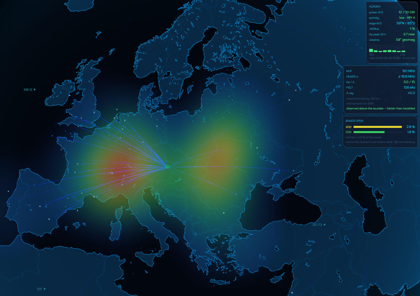
The PROP layer paints where signals are actually getting through, band by band, from every mode this station runs. Everything this station hears is evidence about the ionosphere, and it is all pooled into one picture: WSPR both ways, FT8/FT4/FT2 and JS8 decodes, and the logbook. With the Reverse Beacon Network switched on, so is everything everyone else hears. The PROP button above the flat map in the FT8 and WSPR operating panels draws the same thing under the panel map.
What a bright patch means. Each reception is placed at the midpoint of its path — the patch of ionosphere that bent the signal — and not at the far station. That is the whole design: a map of remote stations would tell you where radio amateurs live, which you already know. This tells you where the sky is working. A path longer than about 3000 km came down and went up again, so it gets a control point per hop.
Two displays:
- ALL BANDS gives each band its own hue and mixes them where two overlap, so a patch that is open on both 20 m and 10 m reads as a blend rather than as whichever band happened to win. This is the “what are conditions like” view and it needs no configuration.
- ONE BAND runs a single band through a blue → green → yellow → red ramp.
On the flat map the controls are the PROP button above it; on the globe they
are the PROP button in the menu bar, which adds the source filter and the
half-life. Both draw the same field.
Signal reports are made comparable before they are pooled. WSPR, FT8, FT4, FT2 and JS8 all quote SNR in a 2500 Hz bandwidth, but their decode floors are ten decibels apart — so what is stored is the margin above each mode’s own floor. Without that, the most sensitive mode on the band would paint as the worst propagation on it. WSPR also declares its transmit power, so a 200 mW beacon is credited for the power it did not use. A logged QSO contributes a path and no signal report at all: an RST is not an SNR, and it counts towards how busy a cell is without ever moving its average.
Memory. An observation’s contribution halves every 45 minutes by default (adjustable in the PROP menu). The ionosphere’s own memory is short, and an opening from two hours ago should not be arguing with one from two minutes ago.
What it cannot show. Without the Reverse Beacon Network, only paths this station has been one end of — so a band the radio is not listening to has no evidence at all, however open it is. Oceans light up because the midpoints of long paths fall there, which is the single biggest thing this adds to an ionosonde map — but Antarctica stays dark because nobody is transmitting from it. The legend gives the absolute path count the brightest cell stands for, so the colours are never relative without saying so.
The Reverse Beacon Network layer. RBN is on by default (under Settings → Spots, and it needs only the callsign from the General tab). It reads the network of CW and RTTY skimmers that listen to whole bands continuously, worldwide, and feeds every spot they publish into this same field. That is the one thing that fills in the bands this radio is not on: while you work 20 m, the map can still tell you 15 m is open to South America, because a few hundred other receivers just heard it.
The difference is not subtle. Monitoring 20 m FT8 alone, the propagation field knows about one band; with RBN running it knows about seven within a minute — including a 40 m that the published forecast calls “Poor” and the skimmers show as the busiest band on the air. Where the forecast and the measurement disagree, the measurement is the one that was actually observed.
It comes with a real limitation, and the map keeps it on its own switchable source for that reason. An RBN line carries two callsigns and no locators, and the network publishes no machine-readable list of where its skimmers are — so both ends of every RBN path are placed at their DXCC entity’s nominal centre. For San Marino that is within the blur the map already applies; for the United States or Russia it can be two thousand kilometres out. Turn the RBN button off in the globe’s PROP menu to see the field without it.
RBN spots never appear in the spot list. There are thousands a minute, they
would bury every human spot in the window, and they are measurements rather than
invitations to call anyone. Narrow the feed with a set/filter line in the RBN
settings if you only care about one continent.
The HEARD ≥ row. The propagation panel gains
a line under the ionosonde MUF: the highest frequency that has demonstrably got
through near your QTH, normalised to a 3000 km path so short and long paths are
comparable. It is a floor, not an estimate — the signal got through, so the
ionosphere was at least this good; how much better is exactly what a reception
report cannot say, because nobody transmits on the frequencies that would have
failed. A cell needs two independent paths before it will claim anything, and
paths under 300 km are excluded because they may never have touched the
ionosphere at all.
The two numbers sit together because they fail in opposite directions: the sounder is a real measurement with dreadful spatial coverage, and this covers the oceans but only bounds. When the observation is above the sounder, the panel says so — the band is better than modelled is the most actionable thing either number can tell you.
The BANDS OPEN chart. The same field, read per band instead of per place,
in a box under the propagation numbers on the globe: one bar for each band with
anything in it, showing how much of the world that band is currently getting
through to. It is the map’s answer to “which band should I be on” without
having to turn the globe and compare patches by eye.
What the bar measures is reach — the share of the Earth’s surface with evidence on it, weighted by area so a polar cell does not count for more than an equatorial one. Deliberately not a count of contacts: forty decodes out of one corner of Europe are one direction open, and a count would call that the best band of the evening. The number beside each bar is that share, and the footer gives the top of the scale, which auto-ranges in steps (1 %, 3 %, 10 %, 30 %) rather than stretching the best band to a full bar — a chart normalised to its own leader would draw the same picture on a dead night as on a good one.
Bands stay in frequency order so the shape of the chart is the familiar spectrum, and each bar takes the hue the ALL BANDS view paints that band in. It inherits the heat map’s memory exactly, because it is read off the same decayed field: whatever the half-life is set to is how long a band lingers here after it shuts. The same caveat applies as to the map itself — a band nobody has listened to has no evidence and no bar, which the footer says out loud.
The BANDS table. Under the BANDS OPEN chart is the same table the main
window’s BANDS window shows — the published CONDX
verdict beside the measured WSPR, PSK, PATHS and REACH, one row per band
with anything to say. It is there so conditions can be read from the globe
without opening the BANDS window over the main view. The footer names the three
sources and whether it is day or night at your QTH. It appears once any of the
three feeds has landed, and only on a desktop or tablet layout — a phone puts
the space weather behind the WEATHER chip, and this table with it.
The heat map is also relayed to the browser’s 3D tab, unlike the awards layer: it is live data about the station’s own conditions, which is what that relay is for.
7.9 The awards layer
The AWARDS layer paints your logbook’s DXCC coverage on the Earth as a map of what is missing. Every entity in the bundled country file gets a marker at its nominal centre: orange and slowly breathing where you have never worked it, amber where you have worked it but no QSL has come back, and a dim green dot once one has. The gaps are what stands out — an evening’s chase has somewhere to aim. A key in the bottom-right corner counts the three states.
It follows the band filter in the AWARDS window
(§10.4), so setting that to 20m repaints the globe as
“what am I still missing on twenty”. The layer needs the Earth to fill a fair
part of the view before it draws — three hundred markers on a planet a few
pixels across is noise, not information — and it is off by default. In the
browser tab it is absent entirely: the logbook lives in the main window, and the
relay carries live data rather than your records.
7.10 The Sun
Sun — which SDO product wraps the Sun:
| Button | Product |
|---|---|
HMI |
HMI continuum — white light. This is the one that shows sunspots. |
193 |
AIA 193 Å — corona and coronal holes |
304 |
AIA 304 Å — chromosphere and filaments |
171 |
AIA 171 Å — quiet corona and coronal loops |
211 |
AIA 211 Å — active-region corona |
MIX |
The 211/193/171 composite |
↻ fetches everything again immediately. Next to the buttons is the age of the
solar image — green when it is current, yellow when the last fetch failed and
you are seeing a cached picture, pink when there is nothing at all. It always
tells you what you are actually looking at; a cached image is never presented as
a live one.
Sunspot markers are sized by each region’s real spot area and coloured by NOAA’s own next-24-hour flare probability — grey for quiet, yellow for likely, pink for a region worth watching. Regions on the far side of the Sun are hidden by the Sun itself, as they should be. CME cones grow from the Sun at the measured speed, so the picture is a direct read-out of where the plasma has got to; a cone drawn faint has its direction estimated from the source region rather than fitted, and cones are coloured cyan through pink with increasing speed.
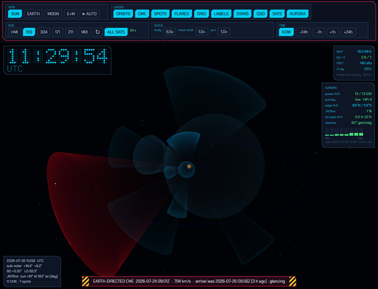
7.11 Scale and time
Scale — the Earth is 23 000 times smaller than its distance from the Sun, so
at true scale it is invisible whenever the Sun is in frame. body exaggerates
Earth and Moon radius (default 20×) and moon orbit stretches the
Earth–Moon distance. Positions are never exaggerated — only sizes — so the
orbits and the CME geometry stay physically truthful. Body scale is capped
against the moon-orbit scale, because past that point the enlarged Moon would
render inside the Earth. Every body also has a glow with a minimum on-screen
size, so nothing is ever invisible however you set these.
Eclipses — during a solar eclipse the Moon’s shadow falls across the
globe: the penumbra as a broad dimming of the daylit side, the umbra as the
small patch of night it really is, and the cloud deck darkens under both. The
occlusion is computed at true scale — the real Moon, at its real distance,
against the real Sun — and painted geographically, so the shadow follows the
Earth’s own body scale and ignores the Moon’s exaggerations entirely: however
swollen the rendered Moon, the shadow crosses the countries the real eclipse
crosses, when it crosses them. The mirror case is drawn too: during a lunar
eclipse the Earth’s shadow sweeps across the Moon, and inside the umbra the
Moon turns the dim copper every photograph of a total lunar eclipse shows —
sunlight bent through the ring of the Earth’s atmosphere, not blackness. There
is no layer button for any of this, because when there is no eclipse there is
no shadow — which is almost always. The total solar eclipse of 12 August 2026
(Greenland, Iceland, northern Spain, greatest at 17:46 UTC) is the nearest
occasion for the one; the total lunar eclipse of 3 March 2026 (greatest at
11:33 UTC) was the most recent for the other.
Time — NOW, −24h, −6h, +6h, +24h scrub the whole scene, bodies and
all, forwards and backwards.
Clock — a UTC time readout sits in the top-left corner. Scrubbing the time
with the ±6h/±24h buttons turns it yellow and relabels it SIM, denoting
that the time displayed is not the current real time.
7.12 The propagation panel
Propagation panel — top right, the numbers worth checking before you call CQ:
| Row | What it is |
|---|---|
MUF |
Maximum usable frequency for a 3000 km path near your QTH, interpolated from the ionosonde network. Green above 24 MHz, cyan above 14, yellow below. |
HEARD ≥ |
The highest frequency that has demonstrably got through near your QTH, from what this station has actually decoded, normalised to a 3000 km path. A floor, not an estimate — see §7.8. Only appears once two independent paths agree. |
Kp / A |
Planetary geomagnetic indices. Green when quiet, yellow from Kp 4, pink from Kp 5 (a storm — polar paths degrade and aurora becomes possible). |
F10.7 |
10.7 cm solar radio flux in solar flux units, the standard proxy for ionisation. Under about 90 the high bands stay shut; over 150 they open up. |
X-ray |
Current GOES soft X-ray class. Turns pink at M class and above, which is when the D layer starts absorbing HF on the daylit side. |
Bands-open chart — under the propagation numbers: one bar per band, showing how much of the world each band is getting through to right now, read off the same propagation field and with the same memory. See §7.8 for what the bars measure and why it is not a contact count.
The line under the MUF says how far away the nearest contributing ionosonde is
and how much to trust the number. MUF is interpolated, not measured at your
location, and the ionosphere changes sharply across the day/night terminator —
a value drawn from sounders 3000 km away on the other side of it is a guess, and
the panel says so rather than hiding it. When no sounder is in range it reads
no sounder.
7.13 Readouts and the CME arrival banner
Readouts — the card at the bottom left gives UTC, the sub-solar point, the solar disk’s B0 and L0 angles, the Sun’s elevation and azimuth from your QTH (and whether it is day or night there), and how many CMEs and sunspot groups are being shown. When an Earth-directed CME is in the data, a banner across the bottom names it with its speed and estimated arrival:
EARTH-DIRECTED CME 2026-07-10 09:48Z · 516 km/s · ETA 2026-07-12 14:20Z (+38 h)
Arrival is a straight-line constant-speed estimate from the fitted cone. Proper forecasts model the CME’s drag against the solar wind and are typically good to about ±6 hours; treat this the same way.
7.14 Where the data comes from
Everything on this list is fetched only while this window is open — closing it stops the background fetcher entirely, and never opening it means no request is ever made. The one exception is the band conditions row: those colour the band menu in the main window, so they are fetched hourly for as long as the program is running, whether or not this window has ever been opened. The two share a cache, so it stays one request an hour either way. The hosts contacted:
| Host | Data | Refresh |
|---|---|---|
sdo.gsfc.nasa.gov |
Solar disk imagery (NASA SDO — AIA and HMI) | 10 min |
kauai.ccmc.gsfc.nasa.gov |
CMEs and solar flares (NASA CCMC DONKI) | 20 min |
services.swpc.noaa.gov |
Sunspot regions, planetary K/A, 10.7 cm flux, GOES X-ray level (NOAA SWPC) | 5–60 min |
services.swpc.noaa.gov |
The OVATION auroral oval grid, auroral hemispheric power, and the three-day planetary K forecast | 15–60 min |
nowcoast.noaa.gov |
Global infrared and visible cloud mosaics (NOAA/NESDIS GMGSI, served by nowCOAST) | 10 min |
prop.kc2g.com |
Ionosonde soundings for the MUF estimate (GIRO network, aggregated by KC2G) | 15 min |
www.hamqsl.com |
Calculated band conditions (N0NBH) — see §2.15. Fetched whether or not this window is open | 1 h |
db1.wspr.live |
Global WSPR activity per band (the wspr.live ClickHouse database) — see §2.15. Fetched whether or not this window is open | 10 min |
celestrak.org |
Orbital element sets: the listings you subscribe to (the amateur group and the ISS by default), plus QO-100 | 6 h |
hamqsl.com is the one entry here that is a single operator’s server rather than
an institution’s, and its published request is hourly polling at most. That is
the interval used, and it is not adjustable.
Everything fetched is cached under solar/ in the config directory and is
loaded before the first network request, so the window opens instantly with
the last data it had and stays useful with no connection at all.
The OVATION grid is issued every five minutes but fetched every thirty: it is 900 kB, by far the largest thing here after the solar imagery, and the oval does not move far in half an hour. Nothing is hidden by that — the aurora panel says what the picture is valid for, so a half-hour-old forecast is labelled as one rather than presented as this instant’s sky.
Credits: solar imagery courtesy of NASA/SDO and the AIA and HMI science teams; CME and flare data from NASA CCMC’s DONKI; sunspot regions, geomagnetic indices, solar flux, X-ray data and the OVATION aurora model from NOAA SWPC; cloud imagery from NOAA/NESDIS’s Global Mosaic of Geostationary Satellite Imagery, served by NOAA nowCOAST; ionosonde soundings from the GIRO network via prop.kc2g.com; satellite element sets from CelesTrak, propagated with SGP4. Planetary positions from JPL’s approximate element set, moon orbits fitted to JPL Horizons, and body maps from NASA/GSFC’s LRO mosaic (Moon) and NASA/JPL-Caltech/SSI’s Cassini global maps (Jupiter, Saturn); coastlines, borders, rivers, urban areas and populated places from Natural Earth.
8. Remote operation
sdroxide can run as a headless server and be controlled from a second sdroxide instance (a native remote client) elsewhere on the network.
8.1 Start the server
sdroxide --server --port 4950
The server opens the configured radio, streams spectrum and audio, and accepts a
WebSocket control connection. The default port is 4950 and the default bind
address is all interfaces (0.0.0.0).
Set a username and password first — see § 7.3. Without one the server is open to anyone who can reach the port, and says so in its log at startup.
WARNING: the timed digital modes (FT8, FT4, FT2, WSPR, JS8 …) are decoded on the server, by the server’s clock. Make sure it is synchronised (
timedatectlmust saySystem clock synchronized: yes) — a server without a time service decodes nothing in those modes, and says nothing about why (3.2).
A station with more than one radio (2.17) serves all of them from the one port. Every radio in the roster is opened — each with its own engine, exactly as the GUI would — and each is reachable in its own right:
| Address | Reaches |
|---|---|
/ws |
the first radio in the roster |
/ws/<id> |
the radio with that roster id, the first one included |
/radios |
the list, as JSON: [{"id":0,"name":"RTL-SDR","path":"/ws/0"}, …] |
The id is the one in radios.json, not a position in the list, so deleting a
radio never renumbers the others. The server logs which radio is on which
address at startup, and curl http://HOST:4950/radios answers the same question
from anywhere. A radio that is not plugged in right now still gets its address
and keeps trying to attach, the same way it would in the GUI.
One connection operates one radio: the single-client rule is per radio, so two people can work two radios of the same station at once — and a native client makes one connection per radio by itself, so one operator gets the whole station in tabs (8.2). A radio id that the station does not have is refused with a 404 rather than quietly answered by a different radio.
The roster can be changed from a client. A headless station’s radios used to
be fixed at start-up: adding one meant editing radios.json on that machine and
restarting the server, which drops everyone on the air. A signed-in client can
now add a radio to the station and close one again — the + and Close on
station described in 2.17 — and the
station acts on it at once: the new radio gets its own configuration scope, its
own engine and its own address, and every client connected is told the roster
changed. It arrives with no interface, so the next step is the same as it is in
the shack: pick one on the Radio page and press Apply / reconnect. The
station’s first radio cannot be closed this way; nothing else is protected, so
treat the sign-in as what it is — the key to the station, not to one radio.
The interlock applies across the whole station: only one of its radios can
transmit at a time, as in the shack. Note that each radio has its own
rigctld.json and tciserver.json in its own scope — if you enable those
built-in servers on more than one radio, give each a port of its own, or the
second one to start finds the address taken.
8.2 Connect a native remote client
From the GUI, on any other machine running sdroxide: open Settings → General, enter the server’s Address and Port in the connect section at the bottom, and press CONNECT.
The station comes up as a radio tab of its own, beside whatever radios that sdroxide already has open — the tab strip at the top of the window switches between them, and ⊞ puts two side by side (2.17). Your own radio keeps running while you work the remote one. To hang up, close the tab from the roster at the top of Settings → Radio; nothing on the server is changed by that. Adding a radio on the server, and closing one there, are separate and clearly-marked actions in the same roster — see 2.17. If the server asks for a username and password, its sign-in screen appears in the new tab (8.3).
The address is remembered in config.toml on the machine you typed it on, so
the next connection is one button. Address takes a host name, an IPv4 or
IPv6 address, or a complete ws://… (or wss://) URL if the server sits behind
a reverse proxy — a URL is used exactly as typed and ignores the port box.
Port is server_port from the server’s own config.toml, 4950 unless it
was given --port.
The same thing from the command line, which starts sdroxide as a client and nothing else:
sdroxide --connect HOST:4950
--connect accepts host, host:port, or a full ws://… URL. A client
started this way has no radio of its own — and can still reach Settings →
General to connect to a second station.
A station with several radios arrives with all of them. The connection you make is to one radio — the first, unless you named another — and the station says what else it has; the client opens the rest beside it, one tab each. So dialling a server that has an RTL-SDR and a Pluto gives you the same two tabs you would have standing in front of them, ⊞ included (2.17). The tab you dialled keeps the name you typed; the others are named as the station names them.
Each of those tabs is a connection of its own. You still sign in once: a station that asks for a password asks each connection separately, and the tabs behind the one you answered let themselves in with what you gave it, for as long as the program runs (8.3). Each tab does carry its own audio and spectrum, though, so on a thin link close the radios you are not using: a tab you close stays closed until you dial the station again.
To open just one radio of a station, name it in the address:
sdroxide --connect HOST:4950/ws/1, or type the full ws://HOST:4950/ws/1 in
the Address box. /radios on the server says which id is which
(8.1).
Either way, a remote client is the full sdroxide GUI running against the server: control, state, memories, meters, spectrum, FT8 decodes and logging, and skimmer spots all work. Receive audio streams down (48 kHz mono), and your microphone is sent up to the server while you transmit. The remote client uses your local speakers and microphone for audio.
8.3 Sign-in: who may operate the station
The server can ask every remote client for a username and password. Set them on
the machine the radio is attached to, either in Settings → General → Remote
access (6.1) or by hand in
config.toml:
[remote_access]
username = "oe1test"
password = "a long passphrase"
Leave username empty to be asked only for the password. Leave both empty —
which is the default, and what every version before this one did — and the
server is open to anyone who can reach it.
Nothing crosses before the sign-in is accepted, and — the part that matters most — an unauthenticated connection does not take the single-client slot. A stranger cannot lock you out of your own radio by opening a socket to it.
One sign-in per station, not per radio. A station serves each of its radios on a connection of its own and asks each one for the password. You answer the first one, and then you are not asked again: the station remembers the sign-in itself, for the time you chose, and every other connection of that station is let in on the strength of it — its other radios, the 3D solar view, and the browser after a reload or a restart. Another station is another door, and asks for itself, once.
In the browser there is one question: tick REMEMBER ME, or don’t. It starts ticked, because being asked again every twelve hours on a station with three radios was the complaint that produced the box. Ticked, the station — not the page — keeps the result for a month: a signed cookie the page itself cannot read. That is why there is no copy of your password in the browser’s storage any more, and why every other radio of the station opens without a field to fill. Unticked is a real answer and it is the tidier one on somebody else’s browser: the cookie then lasts only as long as the browser is open and is dropped when it closes, so nothing is left behind on a shared machine. How long a cookie is honoured is the station’s business, not a number you have to pick — and because the station signs the cookie with its own configured password, changing the password signs every browser out at once, and a station with no password configured has no cookie to give.
If you are on an older station that has no sign-in cookie to hand out, the card says nothing about that — the page falls back to keeping your password in local storage, and Settings → General → Signed-in station names every station that is being treated that way, so you are never quietly holding a station’s password.
SIGN OUT is on that same row, and it is the only thing that can end a remembered sign-in: the cookie is deliberately unreadable by the page, so ending it has to be something the station does. It forgets this device’s sign-in for that station; the connection you are already signed in on stays up until you close it.
The native client keeps the password instead. There is no cookie to hold — the program has no cookie store — so
--connectand the desktop application do what they always have: Remember on this device writes the sign-in toremote_login.jsonbeside your other settings, in plain text. SIGN OUT clears it.
A station compares one answer at a time, so its radios’ tabs take turns signing in and the card says CHECKING… while a tab waits for its own. That wait is not a verdict on the password and is never shown as one: only “username or password not accepted”, in red, means the station actually looked at what you typed and said no.
Sign-in is not encryption. It stops the wrong people operating the radio; it does not hide what you are doing from anyone watching the network, and the password itself crosses in the clear over plain
ws://. On anything but a trusted LAN, run the server behind a VPN or an HTTPS reverse proxy — which is also what the browser client needs before it will give you audio (9.3).
8.4 What to know
- The radio’s own settings travel. Settings → Radio on a remote client
shows the server’s interface panel, read from the
radio.jsonon the machine the radio is attached to: an RTL-SDR’s tuner gain, AGC mode, frequency correction, HF path, IQ correction and bias tee; a Pluto’s gain and filter; an RSP’s LNA state and antenna port; a CAT rig’s PTT and keying. What you change is applied to the running device and saved on that machine, so it survives a restart there. Most settings take effect as you move them; the ones that are fixed when a device is opened — a sample rate, an address — wait for Apply / reconnect, which reopens the server’s radio without restarting it. -
The device questions are asked over there too. Rescan, Discover, Test connection, the diagnostic-report buttons, the serial-port list and the CAT sound-card pickers all ask about a machine — its USB bus, its serial ports, its network — and every one of them is put to the machine the radio is attached to, not to the computer you are sitting at. So a remote or browser client lists the dongles on the server’s bus, the sound cards the rig is wired to, and gets a connection test made from where the radio is. Choosing the interface itself travels with them: pick another one, press Apply / reconnect, and the server switches radios without a restart. If the new one cannot be opened — nobody is at the far end to plug it in — the old one keeps running and the error comes back to you.
The buttons grey out briefly while an earlier question is still out; the far end answers one at a time, so a bus scan cannot interrupt the radio.
- One client at a time. A second connection is refused with a “server busy” message.
- If the link drops, the client dials again by itself. It shows what went wrong in place of the panadapter and says how long until the next attempt — a second at first, doubling to at most half a minute while the far end stays down, and back to a second as soon as a session is accepted. Reconnect now under it skips the wait. The radio keeps running meanwhile, so nothing is lost by a client that was away, and a station’s other radios come back on their own even though nobody is looking at their tabs. This applies to the browser client as well; reloading the page does the same thing.
- A “server busy” message right after a reconnect means the server has not finished letting go of the old session yet. The next automatic attempt gets in.
- A sign-in is asked for again after a reconnect. Each socket is challenged on its own; remember is what makes that invisible.
- Where your screen settings live. A remote client’s own screen — the theme,
layout, waterfall and spectrum look, fonts, Simple UI, the map
layers, the wake lock and the sound welcome message — is kept in this browser by default, private to the browser and
forgotten when its storage is cleared. Settings → UI → Screen settings on
can instead keep it on the server, against the profile you signed in as
(or the station default when that profile has none), so the screen follows the
login back from any machine and a new session does not come up stale.
Only the look travels by default: your control bindings stay with the
browser, so one login cannot rebind another’s keys on a shared station.
Nothing here affects a local radio, which always keeps its settings in its own
file. The per-profile set and the station default are
clientsettings.jsonin the server’s config directory. - Carrying your control bindings too — off by default, and not recommended. The row just under Screen settings on will keep your keyboard and mouse bindings with the profile on the server as well, so they follow your login between browsers and devices. It is off unless you turn it on, and it only does anything when the screen is also set On the server. Turning it on is not a plain tick: a box asks you to confirm first, and nothing is enabled until you do. The reason is that on a station other people use, the keyboard is shared with the station. A profile that carries bindings can rebind another operator’s PTT, Space or tuning keys simply by signing in — and enabling it may have other effects that are not obvious now. Turn it on only where the server is yours alone and you reach it from several devices of your own. Turning it off is immediate and takes effect at once. A client that has not opted in ignores stored bindings entirely, and the opt-in itself stays local to that client: it is a decision you make on a machine, not something a profile carries to another one. (A fork-only feature — it is not in upstream SDR Oxide.)
- No encryption. The server speaks plain
ws://and binds to all interfaces by default. The sign-in (8.3) decides who may operate the radio, but nothing here is confidential in transit. Put the server behind a VPN or an HTTPS reverse proxy if it is reachable from an untrusted network.
9. Web operation
The same server serves a browser client, so you can operate from any device with a web browser.
Browsing the public SDRs (15.21) works here too, and works the same way: the lists are fetched by the station, not by the browser, and the station is what holds the connection to the receiver. So a browser tab can find a receiver on the other side of the world and add it to the station’s roster, where every other client sees it as one more radio.
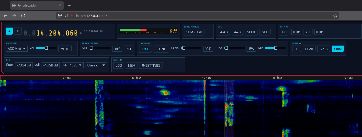
9.1 Serve the web client
Builds that bundle the web UI (compiled with the embed-web feature, including
the packaged binaries) serve it automatically:
sdroxide --server
Then open a browser at:
http://HOST:4950/
The page connects back to the server over a WebSocket at ws beside itself —
the station’s first radio, at /ws when the page is served from the root and
under the same prefix when it is not
(9.4). To open one of its other radios, add the roster id
to the page address:
http://HOST:4950/?radio=1
Two browser tabs on two different radios work the way two clients do; two tabs
on the same radio do not, since one client operates a radio at a time. The
station’s radios and their ids are listed at http://HOST:4950/radios.
If you are running a build without the embedded web UI, point the server at a trunk-built web directory:
sdroxide --server --web-root path/to/sdroxide-web/dist
9.2 What works in the browser
The web client mirrors the native UI: tuning, mode and band changes, the
panadapter and waterfall, receive audio, FT8/FT4/FT2, the logbook, memories, and
meters. Microphone transmit is supported where the browser grants microphone
access — see audio needs a secure context
below. Settings → Radio shows the server device’s own settings panel — its
gains, its antenna ports, and everything else its interface has, read from and
written back to the radio.json on the machine the radio is attached to
(8.4) — so you can swap feedline, wind an LNA back or take
a dongle’s AGC off from a phone. Which interface the server opens is reachable
from here too: the Rescan and Discover buttons enumerate the server’s buses
and network, so you can pick another radio out of that list and press Apply /
reconnect. So is how many radios it has: the roster across the top of
Settings → Radio has the same + as the desktop client — which here can only
mean the station, so it names it and asks before making one — and the × on a
radio’s button offers Close it on station to take one out again. A radio
added this way opens as another browser tab of the same page within a second,
exactly as the station’s other radios do.
The solar system 3D view works too: ☀ 3D
opens it in a new tab, which connects to a separate read-only endpoint and so
does not consume the single control connection — though it is challenged for the
same sign-in, since it is shown your QTH and everything the station is decoding.
The same single-client and sign-in notes as
remote operation apply, and nothing here is encrypted —
put the server behind HTTPS if it is reachable from an untrusted network.
Files go through the browser: every export is a download, and the logbook’s IMPORT and the memory channels’ CHIRP IMPORT open the browser’s own file picker, reading a file in any encoding the native application reads. A channel import goes to the station, which keeps the memory list. An ADIF import goes into this browser’s logbook, which lives in the page’s local storage — not in the station’s log — and browsers cap that storage at around 5 MB per site: a logbook of a few thousand contacts, depending on how much each one carries. Past that the import still reports what it added, but the browser declines to keep it, and after a reload the log is back to what it was. Keep a large log in the native application. Exporting and importing the settings is native only.
9.3 Audio needs a secure context
Browsers only hand out the two APIs the web client’s audio is built on —
AudioWorklet for playback and getUserMedia for the microphone — to pages in
a secure context. Over plain http:// that means localhost only, so:
| How you open the page | Receive audio and microphone |
|---|---|
http://localhost:4950 / http://127.0.0.1:4950 |
work |
https://… (reverse proxy, tunnel) |
work |
http://<lan-or-wan-address>:4950 |
silent — the browser withholds both |
Everything else — the panadapter and waterfall, tuning, decodes, the logbook — works either way; it is only audio that the browser gates. A page opened on a non-secure origin says so in a banner across the top.
This is a browser rule, not a server setting: sdroxide cannot opt out of it. To
get audio from another machine, put the server behind an HTTPS reverse proxy (a
VPN or tunnel with TLS), or forward the port to your own
machine so the browser sees localhost:
ssh -N -L 4950:localhost:4950 user@radio-host
# then open http://localhost:4950
The native remote client (sdroxide --connect) has no such restriction — it
uses your local sound devices directly and carries audio over the same
WebSocket.
The first touch starts the sound. Even on a secure page, a browser will not play audio until you have interacted with it. So a fresh session, or one reloaded with F5, is silent at first, and a large yellow message sits in the middle of the screen:
🔇 Tap, click or press a key anywhere to start the sound
This message does not mean the session has failed. The connection is up, the waterfall runs and the radio is working; only the sound is waiting for you. Click, tap or press a key — anywhere on the page, with a mouse, a laptop touchpad, a finger or the keyboard — and the sound starts and the message goes away. You do not need to touch the volume. That first gesture does nothing else, wherever it lands: it does not tune, press a button, move the waterfall or run a keyboard shortcut, so a receiver you are coming back to keeps its frequency. From the next gesture on, the page works as usual.
While the message is up, moving the mouse, scrolling or pinching on a touchpad does nothing at all, and does not start the sound either: the browser does not count those as a gesture. Click, tap or press a key.
This is the browser’s autoplay rule, not a fault, and an installed web app follows it too. The message is shown only when the page opens — a new session, or a reload with F5 — and never again during the session, whatever happens to the sound later (a network drop, a stutter, a cut).
Once you know what to do, untick Settings → UI → Sound welcome: the message goes at once and does not come back at the next opening. The sound still waits for your first touch, and that touch then works as usual. The setting is kept with your profile on the server, so it follows you to another device; that device shows the message once more at its very first opening, until it has heard your answer from the server.
9.4 Behind a reverse proxy on a subpath
The web client works from any path, not only the root. Behind a reverse proxy
that gives it a prefix — https://shack.example/sdroxide/ — everything hangs
off the page’s own address rather than the top of the host: the WebSocket, the
radio listing, the wasm bundle and the scripts beside it. So the two ways a
proxy can be configured both work, and neither needs anything from you:
- The prefix is stripped before forwarding (Caddy’s
handle_path
/sdroxide/*
, nginx’sproxy_passwith a trailing slash). The server sees ordinary root-level requests; the page’s own links are relative, so the browser puts the prefix back on its own. - The prefix is forwarded intact (Caddy’s plain
reverse_proxy, nginx without the trailing slash). The server takes it off itself — every endpoint it serves is recognised at the end of a longer path, and the client’s files are a flat directory, so anything above the file name can only be somebody’s routing.
A Caddyfile for the second, which is the shorter one to write:
shack.example {
    reverse_proxy /sdroxide/* localhost:4950
}
The address works with or without the trailing slash. Sockets have to be
allowed through — most proxies do that by default, and Caddy needs nothing
said; anything that filters Upgrade and Connection headers has to pass them
or the page will load and then fail to connect.
Serving through HTTPS this way is also what gets the browser to hand over audio and the microphone (9.3).
9.5 Removing an installation completely
Asked for on fork discussion #17, and here it is so nobody has to ask again.
The Debian package (sdroxide, or sdroxide-soapysdr) owns exactly this,
and every line of it goes with the package:
| Path | What |
|---|---|
/usr/bin/sdroxide |
the binary — client and server are the same program |
/usr/share/applications/sdroxide.desktop |
the desktop menu entry |
/usr/lib/udev/rules.d/60-sdroxide-*.rules |
nine dongle rules, so no root is needed |
/usr/share/icons/hicolor/*/apps/sdroxide-brown.{png,svg} |
the icon, in nine sizes |
/usr/share/sdroxide/voices/ |
the speech voice, for spoken announcements |
/usr/share/doc/sdroxide/ |
README, copyright, and four licence notices |
sudo apt purge sdroxide-soapysdr      # or sdroxide — removes every path above
rm -rf ~/.config/sdroxide-brown      # every setting, logbook and recording it wrote
Three things worth stating plainly, because “is anything left behind?” is the real question:
- No systemd service is installed, so a purge cannot leave one running or enabled. A unit you wrote yourself is yours to disable and delete.
- Nothing is written to
/etcor/var, and the installer creates no configuration at all: the program makes~/.config/sdroxide-brownon its first run. That directory — settings, the station roster, the logbook, the reception log, memories, recordings, the solar cache — is the other half of a complete removal.SDROXIDE_CONFIG_DIRputs it elsewhere if you have set that. - The portable tarball adds nothing outside the folder you unpacked it into,
except
~/.local/share/applications/sdroxide.desktopand its icon if you raninstall-desktop-entry.sh;./install-desktop-entry.sh --uninstallremoves both. The Arch package installs the same paths as the.deb.
Not ours to remove: your reverse proxy, your own scripts and backups, and any
other program using libsoapysdr0.8. The RX-888 firmware is inside the binary
rather than in a file of its own, so there is nothing to delete for it either.
A fresh installation has no radio in it. No radios.json, no radio.json,
no per-radio folder — so there is nothing listening and nothing can decode until
one is added at Settings → General → Radio (6.2).
That is the first thing to check after any clean install.
9.6 Phones and tablets
The control strip is eight boxes of a fixed width. On a desktop they sit in a row; on a narrow screen they cannot shrink, only wrap, so the strip would eat the screen and the widest boxes would still run off the side of it. Below about 1100 points wide the strip is replaced by menus, and below about 600 — or on anything shorter than 440 points, which is a phone held sideways — by a compact strip. Settings → UI → Layout (6.3) forces a particular one; Auto is the default and picks from the window.
The same rule applies to the native app, so dragging a desktop window narrow gets the same treatment.
On a tablet, the frequency readout and the S-meter stay as they are — the digits shrink a little in portrait so both fit one row — and the rest becomes a row of menu buttons:
| Button | What it holds |
|---|---|
| PTT | Keys the transmitter. Hold it down to talk, or click it with a mouse to latch it on. |
| RX | Volume, front-end gain, AGC, squelch, the filter width and edges, NB, ANC, NR, BIN |
| VFO | A↔B, A→B, SPLIT, SUB, and the RIT/XIT offsets |
| SUB | The second receiver’s frequency, mode, filter and level (only while it is running) |
| TX | TUNE, the voice keyer, and the drive, tune and mic levels |
| DISP | ☀ 3D, WIDE, FIT, CTR, the panadapter boxes (the spectrum and waterfall switches, peak hold, their speeds and the detail), the skimmers, and the VIEW options (waterfall floor/ceiling, FFT size and scroll direction) |
| SYS | LOG, SPOTS, AWARDS, BANDS, SAT, ISM, PUBLIC SDR, MAIL, MEM, SCAN, SETTINGS, HELP |
A menu stays open until you tap outside it or tap its button again — the top-bar popups do not fade away on a touch screen the way they do under a mouse, because there is no hovering pointer to hold them open.
Tuning buttons. Under the menu row is a full-width row of three: −, the step, and +. Each press moves the dial by the step shown, and tapping the step itself takes the next one — 10 Hz, 100 Hz, 500 Hz, 1, 2.5, 5, 9, 10 and 25 kHz, then round again. It is remembered between sessions.
Settings → UI → First press snaps to the step (off by default) tidies a dial left anywhere: a press goes to the next multiple of the step in the direction pressed — from 7 074 300 at a 1 kHz step, + goes to 7 075 000 and − to 7 074 000 — and every press after that moves by exactly the step. At a 9 kHz step that is the medium-wave channel raster; at 1 kHz, the zeroes on a printed channel list (issue #422).
This is the one thing a touched screen had no way to do (issue #380). A desktop tunes three ways and a phone has none of them: there is no wheel, so scrolling a digit on the readout is unreachable; tapping the panadapter lands where you tapped, which is a gesture nobody makes twice when the next station is 3 kHz away; and typing the whole frequency in to move one channel is data entry rather than tuning. Stepping in round amounts is what working down a band actually is.
The row costs one button’s height of waterfall, so it can be switched off: Settings → UI → Tuning buttons. It is never drawn on a desktop, which has the wheel and the readout’s own per-digit scrolling.
On a phone the readout shrinks too, and the A/B selector and the other VFO’s
frequency move into the VFO menu; a small A or B before the digits says
which one you are tuning.
PTT is press-and-hold on both, and a finger never latches it: a latching control an inch from a waterfall you pan with your thumb is one mis-tap away from a transmitter left on. Lifting your finger always drops it, including when the browser takes the touch away because you switched tabs.
A mouse gets the latch back, because a mouse is not the thing that rule guards against — and these layouts are not only touch screens, since Auto picks the tablet strip for any window under 1400 points wide and you can force either one outright. Press and hold to talk, exactly as a finger does, or click the button to leave it keyed; the next press lets go. Dragging off the button before releasing cancels the latch, so an accidental press ends the over rather than leaving it on the air.
The digital-mode panels
Every operating panel (3) is two columns side by side — an activity list and a working area, or a picture and a gallery. A tablet keeps them that way. A phone cannot: the two want 180 and 220 points before either has drawn anything, which is more than the screen, so it shows one at a time with a row of buttons above them.
The panes, by mode:
| Mode | Buttons |
|---|---|
| FT8, FT4, FT2 | DECODES · QSO · WFALL |
| JS8 | HEARD · CHAT · WFALL |
| FSQ | HEARD · TRAFFIC · WFALL |
| SSTV, SSTV-FM, RIFP | RECEIVE · SEND · WFALL |
| Weather fax | CHART · SAVED · WFALL |
| RF Paint | TEXT · IMAGE · WFALL |
| PSK, RTTY, Olivia, THOR, Contestia, Hell, RADE | PANEL · WFALL |
WFALL is the waterfall, zoomed to the mode’s sub-band and filling the screen. It is a view of its own rather than a strip above the panel because a third of a phone’s height is not enough to work a mode and watch a band — split that way, both were too small to use.
In FT8 and FT4 the count of stations decoded in the last slot sits at the right of the button row, so it reads from all three views, and answering somebody from the decode list switches to QSO by itself — you started an exchange, so the panel shows you the exchange. In SSTV the live picture and the received gallery stack one above the other instead of sharing the width.
The FT8/FT4/FT2 world map is gone on both compact layouts. It is the largest thing in that column and the only part of it that is neither the state of the contact nor a control that changes it, and on a tablet it was taking the room the transmit buttons needed. The same stations are still on the panadapter and in the 3D view.
Touch gestures on the waterfall:
| Gesture | What it does |
|---|---|
| Drag | Pans the view and takes the dial with it, with the same flywheel coast as a mouse |
| Two-finger pinch | Zooms the span about the point between your fingers — there is no scroll wheel to do it with |
| Tap | Tunes to that frequency |
| Drag a passband edge | Sets the filter. The grab zone is wider than under a mouse, but never more than a third of the passband, so tapping inside a narrow CW filter still tunes. There is no Ctrl to hold on a touch screen, so the AM and FM modes always pair their edges here |
Buttons, sliders and entry fields are all drawn larger on a touched layout, so a row of controls is a row of finger-sized targets rather than 22-point ones.
Remember that audio needs a secure context (9.3): a phone opening the server over plain HTTP on the LAN gets the waterfall and the controls but no sound at all.
Installing it to the home screen
In a browser tab, a third of a tablet’s screen is address bar and toolbars, and they never go away: the page deliberately does not scroll — a drag pans the waterfall instead — so the browser never hides its own chrome the way it does on an ordinary site.
Install it instead, and it launches with none of that:
| Browser | How |
|---|---|
| Samsung Internet, Chrome, Edge (Android) | menu → Add page to Home screen |
| Safari (iOS, iPadOS) | Share → Add to Home Screen |
Then launch it from the new icon, not from the browser — opening the same address in a tab still shows the tab. On Android it is installed as a web app and runs genuinely full screen, with no address bar and no status bar; on Samsung DeX it behaves as an ordinary desktop window.
A private or incognito window cannot install it, and that is the browser, not the program. Chrome and Firefox both refuse to install an app from a private window — the option is simply not there in the menu — and no setting on the station changes that. It is worth saying plainly because it looks like something misconfigured: everything else in a private window works, and works normally. The one thing a private window does not keep is what the browser holds — your screen and your key bindings — so in one you sign in and the station supplies them instead of the device remembering them. That is the same path a profile on any other machine takes, and on this build the profile is held on the station, so a private window is in no way second class. It is only the installed icon that is unavailable.
This needs the same secure context as audio (9.3). Over plain HTTP on the LAN a browser will offer a plain bookmark at best, so the two reasons to put the server behind HTTPS — or to reach it over a tunnel, a VPN or Tailscale — are the same reason.
The screen can stay awake while the client is in front: tick Settings → UI → Wake lock (off by default, because it costs battery; kept with your profile on the server). A receiver is watched rather than read, and a tablet left alone blanks after half a minute; installed full screen that takes the whole application away and puts a lock screen in front of it. The client asks the browser to hold the screen on, gives that up whenever you switch away — a client in the background has no business keeping your screen lit — and asks again when you come back. The line beside the box says when the browser does not have it, or refused it.
The padlock locks the screen against stray fingers. It sits on the phone and tablet strips, just after the MEM chip; the desktop layout has none.
- Tap it and the screen is locked: frequency, band, mode, filters and the waterfall stop answering a finger. Reception and audio carry on.
- Hold it for 3 seconds to unlock. A ring fills round the padlock while you hold; lifting early leaves the screen locked.
- After an unlock the padlock rests for 10 seconds. A tap on it then does
not lock the screen again, so the finger that has just unlocked it cannot
lock it straight back. A tap in those 10 seconds shows
UNLOCKED · lock in N s; after them, a tap locks as usual.
The home-screen icon is sdroxide’s own, the same artwork the desktop application and the packaged builds use.
10. Spotting, awards, and QSL upload
SDR Oxide features spots you can click to work, automatic callsign lookup, one-click QSO upload, and award tracking. This chapter is about what they do; the settings behind them are on the Spots (§6.5), FreeDV (§6.6) and Uploads (§6.7) tabs of the Settings window, and they are surfaced by the SPOTS and AWARDS buttons in the System module. Your callsign and grid come from the General tab and are used by all of them.
All of this runs on the machine with the radio (the server, in remote/web mode),
so a browser or remote client uses it too. Credentials are stored in plaintext in
net.json (see §13).
10.1 Spot feeds (DX cluster, POTA, SOTA, PSK Reporter)
FreeDV Reporter is configured separately, on its own Settings tab — see §10.5.
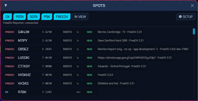
Enable the feeds you want — DX cluster, POTA, SOTA, PSK Reporter — on the Spots tab of Settings (§6.5) and press APPLY. Spots then appear two ways:
- On the panadapter — colour-coded, clickable boxes along the bottom of the waterfall (DX = cyan, POTA = green, SOTA = amber, PSK = violet, FREEDV = pink, BC = yellow-green — any of which you can retint under Spot label colours on the UI tab, §6.3), each with a leader line down to the spotted frequency. Located spots (POTA parks, PSK reporters, FreeDV stations, broadcast transmitters) also appear as dots on the FT8 world map.
- In the SPOTS window — a filterable list (toggle DX / POTA / SOTA / PSK / FREEDV / BC, or IN VIEW to show only spots inside the current panadapter span). Each row shows the source, callsign, frequency, mode, age and reference/comment, and a green NEW flag when it is a DXCC entity you haven’t worked yet.
Switching a category off hides it everywhere at once — the list, the panadapter labels and the world-map dots — and the six category buttons are remembered between sessions, so a category you have no use for stays off. (IN VIEW is not: it is a way to read a crowded band for a moment, not a standing preference.)
Search — the ⌕ box below the buttons does a fuzzy search over everything in
the list: callsigns, station and transmitter names, comments, park and summit
references, and the frequency written either way, so 9420, 9.420 and avlis
all find the same station. Letters need only appear in order, so bbcws finds
“BBC World Service”; several words are all required, so bbc asc narrows to the
BBC transmissions from Ascension. Matching rows are ranked best-first while you
type, and a counter under the box says how many of the total matched. The search
narrows the list only — the panadapter labels stay where the frequencies are.
Click a spot — on the panadapter or in the SPOTS list — to tune your VFO onto it, switch to its mode, and open a pre-filled New Entry in the logbook (call, frequency, mode, and any grid/reference from the spot). If auto-lookup is on (below), the name/QTH/grid are filled in too. CW spots are tuned a sidetone pitch low so the signal lands in the CW passband. Broadcast stations only tune — they have no callsign to log or look up.
Band openings
The OPENINGS chip at the top of the SPOTS window opens a live detector that answers a different question from the spot list: not “who is being heard” but “which paths have just come alive”. It watches the spot feeds the window already has — and, on 11 m, this station’s own WSJT-CB decodes — and flags a band and continent-pair whose recent activity has surged past its own baseline over the last three hours. A path that was quiet and suddenly carries a burst of new stations is an opening; a band that is simply busy is not.
Each detection names the band, the direction (which continent-pair), how far past its baseline it is running, and how long ago it opened; a path that goes quiet again is retired on its own. The section has its own draggable divider, so a listener watching a big surge can give the detections more room and the spot rows less. It is a surge detector over the spot traffic, not a propagation forecast: it says what the feeds are showing now.
10.2 Callsign lookup
Auto-fill operator details from an online callsign database — QRZ.com (needs an active XML-data subscription) or HamQTH (free). Pick the Provider and enter its credentials on the Uploads tab of Settings (§6.7).
Tick Auto-fill name/QTH/grid on spot click & QSO to look a call up automatically when you click a spot, start an FT8 QSO, or finish typing a call in the entry form. Either way, the LOOKUP button in the New/Edit Entry form does it on demand. Lookups only fill fields you’ve left blank, so they never overwrite what you typed; results also enrich the matching logged QSO (name, grid, DXCC, zones).
10.3 Uploading QSOs (eQSL, QRZ, HamQTH, Club Log, LoTW)
Enter your QRZ Logbook, eQSL, HamQTH and Club Log accounts on the Uploads tab (§6.7) — one tab per service, each with a Test button that checks the login against that service before a QSO depends on it, worth doing once, since otherwise the first sign of a wrong password is an upload that failed hours after the contact. Then either tick Auto-upload each new QSO and, on each service’s tab, the service itself, to push every QSO as it is logged; or upload individual QSOs from the logbook with the per-row UP button. Each upload sets that QSO’s status flag (the ↑ in the logbook), and failures are reported in the SPOTS window’s status line.
HamQTH needs no separate account from the callsign lookup — the same username and password do both, and if you already look calls up on HamQTH there is nothing more to enter. Its logbook wants a date, time, callsign, mode, band and both signal reports on every contact; a QSO missing one is refused before it is sent, naming the field, rather than coming back as HamQTH’s unexplained QSO Rejected (which is also what it says for a duplicate). Upload one contact at a time, as sdroxide does — HamQTH asks specifically that this route not be used to push a whole log, and offers a file upload on the website for that.
LoTW upload is deliberately not automated — LoTW requires a signed upload via ARRL’s TQSL. Export your log to ADIF from the logbook and sign/upload it with TQSL as usual.
Confirmations — enter your LoTW login (and/or use your eQSL credentials) and press SYNC CONFIRMATIONS. sdroxide downloads your LoTW/eQSL confirmations and matches them against the log to set the ✓ (confirmed) status, which drives worked-vs-confirmed in the awards view. (LoTW upload stays manual; only the confirmation download is automated.)
10.4 Award tracking
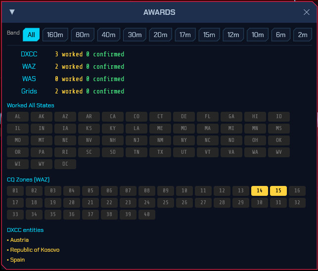
The AWARDS button opens a live tally computed from your log:
- DXCC (entities), WAZ (CQ zones), WAS (US states) and grid squares, each shown as worked and confirmed counts, with a per-band filter across the top.
- The WAS and WAZ grids colour each slot grey (not worked), amber (worked) or green (confirmed); the DXCC list marks confirmed entities.
DXCC entity and CQ/ITU zone are resolved from the callsign using a bundled
country file (cty.dat), so awards work even for QSOs you never looked up —
though a lookup adds exact zones and state. A QSO counts as confirmed once any
of LoTW, eQSL or a paper card is received for it. The same entity resolution
flags new DXCC entities in the SPOTS list, so you can spot an all-time-new
one at a glance.
Nothing here is ever reset, and there is no control to reset it: the tally is recomputed from the logbook every time it is shown, so it is only ever a statement about the log as it stands. Delete a QSO and the entity it brought in goes with it; import an ADIF and its entities appear. There is no per-year or per-season rollover either — DXCC, WAS, WAZ and grids are all-time awards. The band filter is the only thing that narrows what is counted, and it is a view, not a state.
On the globe — the 3D view’s AWARDS layer
(§7) paints the same tally on the Earth as a “what am
I still missing” heat map: every DXCC entity in the country file gets a marker at
its nominal centre, orange and breathing where you have never worked it, amber
where you have but it is unconfirmed, and a dim green dot once a QSL has come
back. A key in the bottom-right corner gives the counts. It follows the same band
filter as this window, so switching to 20m here repaints the globe as “what is
missing on twenty”.
The grid tracker — the GRID button (System box) opens the log’s worked squares on their own map: each 4-character Maidenhead square is filled on the flat world map, amber where worked and green where a QSL has come back, with your own locator marked on top. Drag to pan and wheel to zoom; the square under the pointer is named. The HEARD layer shades, in cyan, the squares on the live decode list rather than the log — what is on the air right now — which is what makes the window useful to a shortwave listener with no log of their own. A square that is both heard and worked reads as worked.
An 11 m exchange carries no locator, so a CB log has no squares to draw. The tracker has a COUNTRY mode for that: each worked DXCC entity is marked at its nominal centre instead, resolved from the callsign exactly as the awards tally does (the leading digits of a CB call are its country). GRID and COUNTRY toggle between the two, and the window opens on whichever the log actually holds — a CB log opens on countries rather than on an empty grid map. The heard layer follows the mode.
10.5 FreeDV Reporter (qso.freedv.org)
FreeDV Reporter is where FreeDV operators announce where they are listening and who they are hearing. SDRoxide talks to it in both directions: your station appears on the site, and everyone else’s appears in SDRoxide as spots.
Turn it on and point it at a server on the FreeDV tab of Settings (§6.6). You are only shown to others while the radio is in RADE mode; in any other mode the connection stays up but your station is hidden, so the site never lists you as working FreeDV when you are actually on CW.
While the feature is on, SDRoxide reports your transmit frequency as you tune and
your transmit/receive state as you key up, and reports your software as
SDRoxide <version>.
With more than one radio the entry is still the station’s, not the tab’s: the session belongs to the first radio in the roster, but whichever radio is in RADE is the one whose frequency and transmit state go out, and the station is hidden only when none of them is. The settings on the FreeDV tab are likewise the station’s, so applying them from any radio’s window changes the one session rather than opening a second under the same callsign.
Callsign exchange. RADE carries a callsign in the frame at the end of each over. SDRoxide transmits the callsign from your digital-mode configuration there, so other FreeDV stations can identify you, and decodes the far end’s, showing it as the DX call and reporting it. This uses the same over-the-air format as FreeDV GUI, so the two interoperate.
Checking it works without going on air: sdroxide --freedv-reporter-probe 20
connects read-only for twenty seconds and prints the stations and events it saw.
It uses the server’s view role, so it needs no radio and never makes you visible
to anyone.
10.6 Broadcast stations on longwave and shortwave
SDRoxide labels longwave and shortwave broadcast stations on the waterfall in orange, alongside the network spots — so a carrier on 225 kHz comes up as Polskie Radio Program 1, Solec Kujawski rather than as an unexplained signal. Click one to tune it in AM; unlike a cluster spot it opens no log entry and looks up no callsign.
Only stations on the air now are labelled, which is what makes a schedule of this size usable: the three schedules below hold around 8,000 transmissions between them, of which some hundreds are on the air at any moment. Each carries a UTC window and, where the broadcast does not run daily, a day mask; the list is re-filtered against the clock every minute. Entries with no window — the longwave transmitters, the standard-time stations, the round-the-clock private shortwave stations — are always shown. Turn the whole category off with the BC button in the SPOTS window.
A band is still busy at prime time (the 31 m band carries 50–95 transmissions at midday UTC), so zoom in or use IN VIEW when the labels crowd each other — only five rows of labels are drawn, and the rest are dropped.
Because every entry names a real transmitter site with its coordinates, the stations also appear as dots on the FT8 world map, and tuning one draws its path on the 3D globe: a great-circle arc from your grid square to the transmitter, labelled with the station and site, exactly as a QSO or a weather-fax chart is. That turns “a signal on 15400” into “this came 8,000 km from Ascension Island”. It needs your grid set on the General tab, and the QSO layer on.
Only the station you are actually tuned to is named. A crowded band carries dozens of schedules at once, and labelling all of them buries the one under the dial. So the waterfall names the station on your frequency and nothing else; the rest — country, city, transmitter coordinates — is in the SCHEDULE window. If two broadcasters genuinely share a carrier, both are named, because those are two facts about what is on air and hiding one would be a lie.
The path to a station is drawn with its own twilight: each dot along it is lit or dim according to whether that point is in daylight, so you can see which half of a path is dark rather than being told a percentage. It fades through twilight rather than switching at the terminator, and a night dot keeps a faint outline — a path that vanished would read as “no path”.
The schedule downloads itself
Shortwave schedules are reissued twice a year, so SDRoxide keeps its own copies current instead of shipping a snapshot that goes stale. Three sources are fetched, each on its own terms, and all of them go into one store:
| Source | What it is | Notes |
|---|---|---|
| EiBi | The long-standing schedule, from eibispace.de. | Plain HTTP, because its certificate is expired — see below. |
| Aoki | A second schedule, read from the season’s own package. | The same station often appears in both. |
| HFCC | The HFCC operational schedule. | Carries transmitter sites and positions. |
How each is fetched:
- On first run they download in the background and are cached under
broadcast/in the config directory (§13). - At each season change — the last Sunday in March and the last Sunday in October — the cache no longer matches the season, so the new files are fetched. The check happens at startup and once a day thereafter, and the previous season’s files are deleted once the new ones land.
- Until then, or if there is no network, the EiBi copy compiled into the binary is used. A failed download changes nothing except freshness; each source reports its own failure and the others carry on, so one that cannot be had never costs you the rest.
The Spots settings tab lists every source whether or not it has been fetched, showing how many transmissions each holds and giving it its own Download button beside Download all now. A source that has never been fetched reads not downloaded rather than simply being absent — a row that only appeared once it had worked makes “did it download?” unanswerable.
Downloads run on a worker thread, so they never delay startup, and a file is written to the cache only after it parses into a plausible schedule: a captive portal’s login page cannot replace your station list. Aoki arrives as a zip holding a Shift-JIS text file, so it is unpacked and decoded as its own format rather than as CSV; HFCC arrives as one package holding the schedule and its reference tables, so the names cannot go stale against the schedule they belong to. Each source’s own week numbering is converted to this program’s as it is parsed — Aoki and HFCC both count the week from Sunday, this one from Monday — because doing it in two places is how every station ends up a day out.
The EiBi download is plain HTTP for the expired certificate. Nothing is trusted on the strength of the transport: the file is parsed into typed rows and rejected unless it looks like a season’s worth of transmissions.
Your own stations
broadcast_stations.json in the config directory is yours alone. SDRoxide never
writes it, and merges it over the downloaded schedule each time it loads:
- an entry with the same name and frequency as a scheduled one replaces it — that is how you correct a wrong site or time;
- anything else is added — a local station, a pirate, a relay the schedule does not carry.
The file does not exist until you create it, and holds only your entries rather than a copy of everything, so it stays small and never goes stale. Reload on the Spots tab re-reads it after an edit.
Import my station list…, beside it, reads a list you already keep somewhere else and merges it in. It accepts this JSON, a CSV, or a plain text list, because a listener’s list comes from wherever they kept it and being asked to convert it first is what stops them:
BBC World Service 15400 kHz
5010,Radio Prague
The unit is decided by the number. Shortwave here runs from 3 kHz to 130 MHz,
so a bare number at or above 1000 is kHz and anything below it is MHz — 15400,
15400 kHz and 15.4 all land on the same row without being told. Rows merge by
name and frequency rather than being added twice, and a line with no frequency in
it is skipped rather than half-read. Your own list is a schedule — what you
expect to hear — and is not the reception log, which records what you did hear.
This is a schedule, not the log. The SWL LOG records what you heard; this
records what is expected to be on air, which is what the waterfall labels against.
Mixing them would put a station in the picture that was never transmitted. (Upgrading from an earlier SDRoxide
that seeded a full copy here: that copy is moved aside to
broadcast_stations.json.bak on first start, because laying a stale season back
over a fresh one would duplicate hundreds of transmissions. Nothing you wrote
yourself is touched.)
Each entry needs only a name and a frequency in kHz:
{ "name": "BBC", "freq_khz": 15400, "site": "Ascension Island",
  "country": "Ascension Island", "lat": -7.9, "lon": -14.3833,
  "lang": "English", "target": "West Africa",
  "start_utc": 1800, "end_utc": 1900, "days": "12345" }
| Field | Meaning |
|---|---|
name, freq_khz |
Required. Frequency in kHz, as broadcast schedules print it. |
site, country |
Transmitter site — the country is where the transmitter stands, not where the broadcaster is from. |
lat, lon |
Transmitter position in degrees. Both or neither; without them there is no map dot and no globe arc. |
power_kw, lang, target |
Shown in the spot row. |
mode |
Only if it is not plain AM — SAM, USB, … |
start_utc, end_utc |
UTC HHMM. Leave both out for a round-the-clock station. end_utc below start_utc wraps past midnight, so 2200–0200 works. |
days |
Digits 1 (Monday) to 7 (Sunday), e.g. "12345" for weekdays. Empty means daily. |
season |
"A" (last Sunday in March to last Sunday in October) or "B". Absent means both. |
The SCHEDULE window
In SWL mode the strip’s ham chips give way to SCHEDULE and SWL LOG (§6.3), and the SCHEDULE window is where the listener browses the table: it turns the same EiBi schedule the waterfall labels into the list a listener works from.
At the top are the filters — a UTC time (or now), free text over name, site, country, language and target, language, target, and a metre band. On the chip row below them are ★ FAVS, which shows only the stations you have starred, and Source, which narrows the list to one schedule or shows all of them.
Source reads all of them by default, and that is deliberate. The store holds every downloaded schedule, so one broadcaster listed by two of them appears twice — and the repetition is the point here: this window is where the detail belongs, and the repetition is accepted in exchange for never querying several databases to answer one question. It is the panadapter that collapses it, by naming each station once. The label says all of them rather than any source’s name, because a box reading “EiBi” while three schedules are loaded would be a control that cannot be misread. A row can be TUNEd (the same tune as clicking its label on the waterfall) or LOGged straight into the reception log with the station, language and site already filled in.
SOLAR TIME puts each row’s local time at the transmitter beside its site, from the coordinates EiBi carries. It is mean solar time — the Sun’s clock, four minutes a degree from the site’s longitude — and deliberately not a civil time zone, because that would need a country-polygon dataset a fork should not carry for this. It is labelled solar rather than local for that reason: it knows nothing of daylight saving or of a country’s zone borders. Hover the column for the site and longitude it was read from. A listener planning in the broadcaster’s evening is the thing it is for.
Where the data comes from
The shortwave entries are EiBi’s seasonal schedule, parsed by SDRoxide itself —
the same code path for a downloaded file and for the compiled-in one, so they
cannot behave differently. Transmitter coordinates and the language, country and
target-area names come from EiBi’s README, which changes very rarely and is
therefore compiled in rather than fetched; tools/gen_broadcast_codes.py
refreshes those tables and the offline fallback schedule:
tools/gen_broadcast_codes.py --season b26
Longwave and the HF standard-time stations are not in EiBi’s file — it starts at
2300 kHz and skips time signals — and are maintained by hand in
crates/sdroxide-types/src/broadcast_seed.json.
The LISTEN window
Where the SCHEDULE window is a table to browse, LISTEN is the band to listen on. It opens beside SCHEDULE and answers two questions at once: what is on around this frequency, and where is it coming from.
- ON THIS SPAN lists every station whose schedule covers the part of the band currently in view. A station listed by two schedules appears twice — the same repetition the SCHEDULE window keeps, and for the same reason.
- Click a station, on the map or in the list, to select it. Clicking it also tunes there, which is what a click on a map means everywhere else in this program: the SCHEDULE rows tune, and the decode maps steer the beam. Earlier, LISTEN only selected, and the operator found it in a minute — “clicking a station is not changing the frequency”.
- Under the station: its frequency, country, transmitter site and language, then distance, bearing, and the share of the path in night. Grey-line absorption is why a long path is open or not, and that last figure is the one to read before chasing a weak signal.
- The map shows the path from your locator to the station, lit by its own twilight. A station whose position no schedule carries says so rather than drawing a line to nowhere.
- Write what you heard in the box, then LOG — which files it in the reception log with the station, site and language already filled in.
Its own geometry: HISTORY (off by default) keeps the span you were on rather than following the dial.
The SWL LOG window
Where the SCHEDULE window is the table a listener works from, the SWL LOG window is the record of what was heard: a reception log, and the tools to work it — the antenna in use, the reception report, and the log’s CSV and ADIF exports. It is the listener’s counterpart to the LOGBOOK.
+ NEW logs the station the receiver is on right now, with the frequency, the mode and the S-meter reading taken from the live radio, and — when the dial sits on a station the schedule knows — its name, language, transmitter site and report contact, the same prefill LOG on a SCHEDULE row gives, so a catch is a judgement and a send. Where the schedule has nothing on the frequency, a station name you have logged on it before is offered instead. The entry form holds the rest of a reception: the station name, the frequency and mode, a language, the SINPO or SIO figures, and your own notes.
Each row in the log carries an rcl button: it tunes back to that reception’s frequency and mode in one click, so a listener can check whether the station has returned on the same channel at the same time another evening. It sets the mode through the listener’s route, so a recalled catch always comes back as it was logged rather than being refused by the band rule that governs what may be transmitted.
The form and the row keep the receiving station’s locator — where the reception was made — pre-filled from your own grid on the General tab and editable per entry. It is the comparison that matters when the same station is heard from two places, or from two aerials. On the row it takes the place the notes used to occupy; the notes are a hover over the station name, so a long one no longer pushes the row about.
The transmitter site is deliberately not a field: a listener almost never knows it, and the one source that does is the schedule, which fills it in when a row is LOGged or when + NEW lands on a scheduled frequency. It rides on the saved entry and shows on the row’s hover when it is there, beside the notes.
The entry form carries a Pirate tick for an unlicensed — “pirate” — broadcast, the kind of catch shortwave listeners go looking for. It is the listener’s judgement and nothing infers it. A reception so marked wears a small Jolly Roger in the log list, and the tick survives editing the entry later.
The Antenna box at the top of the window is the aerial in use, in your own words — “Longwire 20 m”, “MLA-30 loop”, a mini-whip. It is session state, set once when you start listening, because an aerial is swapped far more often than a settings page is opened; and it is not a property of the radio, so it stays on this screen rather than in Settings. Each reception captures it when it is logged. REPORT writes that reception out as a text report to save and send — the numbers, the received-at locator and the aerial, signed with your report identity — and names the program there as sdroxide_SWL, so a broadcaster can tell it apart from the amateur build.
MAIL REPORT… in the entry form is the same report, written and opened in your
mail client instead of saved as a file. It is available when the form carries an
email address — which is what a known station means here: one the schedule
holds a report contact for, filled in by + NEW or by LOG on a SCHEDULE
row. Where the schedule has no address, the chip is greyed and says so, because a
reception report with nowhere to go is not a reception report.
The report itself is built from the form as it stands, so a SINPO you have
improved and then mailed without pressing SAVE still goes out as you typed it,
and it is generated from exactly the same conversion SAVE uses, so the two cannot
disagree. Every field you left blank is left out entirely rather than blanked
or dashed: a report reading Grid: — is a line the station has to interpret, and
one reading Grid: with nothing after it looks like an empty string rather than
an unknown. An unjudged reception states no figures at all, rather than five
defaulted ones nobody heard.
The subject names the station and the date and nothing else — it goes to a
broadcast engineer filing it by date, not to a contest logger. A transmission you
marked Pirate is reported plainly, as a fact the station can act on.
It sends nothing. The picture you configured in Settings is written out and
named in the body, and the message opens with the report ready; attaching it — and
a soundclip, if you cut one with REC’s 30-second quick clip — is your own
click in your mail program. A program cannot put a file in a message without
being a mail client, with an account and a password and a server, which is a
different program with its own security to consider. This does everything up to
that point and nothing beyond it.
Two settings under Settings → UI, in the SWL section, decide what a report
carries: Report picture (a path on this computer — your own card, a
photograph, whatever you want the station to see; one image, used for every
report) and Report note (your standing note — who you are, what you listen
on, anything a station asks once rather than per letter). Both are optional and
genuinely so: a plain-text report is a perfectly good report, so leaving them
empty breaks nothing. The picture row is absent in a browser tab, because the
setting names a file on this computer and there is no such thing there — it is
left out rather than shown dead.
A reception is not finished when it is heard: an SWL’s loop is hear → report → await QSL, and the log records the whole of it. report sent stamps the day the report went out — REPORT sets it too, since writing the report is that step — and QSL received stamps the reply or card when it arrives. Each is a date rather than a plain tick, so the log keeps when as well as whether; unticking one clears it. The row carries a small sent or QSL mark after the locator, so the catches still owed a report, or still awaiting a card, are the ones with no mark. The two steps ride on the saved entry with everything else, so they survive a restart and travel with the log.
The row of controls above the log is how you read a log that has grown past a few dozen catches. Show is a find box over station, language, transmitter site and notes; beside it a band and a day menu — each listing only the bands and days the log actually holds — and a Pirates only switch for the unlicensed catches. CLEAR drops every filter at once, and while any is on the header says how many of the log are showing. The filters are how you are reading the log now: they never change or hide what was recorded, and they are not saved. The window’s own header counts the whole log at a glance — how many heard, and how many of those reported, QSL’d and pirates — so the filters above it never change what those totals say.
CSV and ADIF at the end of that row save the whole log in one file,
filtered or not — CSV for a spreadsheet, one row per reception, and ADIF as
reception records (SWL=Y, the station in CALL, and the report-sent and
QSL-received dates in the fields ADIF keeps for them). The single-entry
REPORT is the one to send to a broadcaster; these are the log’s own backup
and export.
The window’s other controls are the listening tools in their own right: JOBS for scheduled recordings, REPLAY for the last two minutes of audio, SIG ID (see §10.7) for what is on the dial, and the Tone row for bass, mid and treble shelves on the demodulated audio.
LOUDNESS, at the end of that row and in the RX strip’s EQ popup, lifts the bass (up to +12 dB, around 120 Hz) and a little treble (up to +6 dB, around 6 kHz) as the volume goes down, because the ear loses the ends of the spectrum first at low level. It follows the volume knob as you turn it, works with the tone shelves on or off, is flat at full volume, and is never more than the volume it compensates — so it cannot make the speaker play louder than full volume would, nor clip it. Narrow modes (SSB, CW) carry little treble, so there it is mostly a bass lift.
Both the Tone shelves and LOUDNESS are off by default — nothing changes until you tick the box — and both are per-mode settings (Per-mode settings): what you set is remembered for the mode you are in, every other mode keeps its own (off until you set it there too), and the value comes back with the mode and after a restart. The circular-arrow reset chip and Settings → General → RESET EVERY MODE switch them back off. They shape the main receiver’s speaker audio only.
10.7 Signal identification
SIG ID, beside JOBS in the SWL LOG window, opens a guide to what is on the dial. It reads the dial frequency, the mode and the receiver’s passband, ranks a built-in catalogue against them, and lists the candidates — what the signal is, what it is modulated with, how wide it is, and a one-line description. The sigidwiki link on a row opens the matching sigidwiki page for a waterfall and a recording.
The ranking puts an exact mode match first, then the frequencies and bands the signal is known on, then how close the passband is to the signal’s own width. So tuning to 14.074 in FT8 names FT8, tuning to 27.185 in AM names the channel, and tuning to 518 kHz in NAVTEX names NAVTEX. It is a guide rather than a verdict, and the entries under the top name are the ones it weighed against the dial.
The Find box searches the whole catalogue instead of the dial — “weather”, “aircraft”, “meteor” — which is the way to reach a signal with no frequency to type, and reads as a map of what is out there rather than a description of what is playing.
The catalogue is built into SDRoxide and describes signals, not stations: around sixty entries covering the amateur, broadcast, marine, aviation, utility, time and satellite services the receiver knows. It carries no waterfall images or audio samples and nothing copied from another identification database — the sigidwiki link opens that content in your browser rather than redistributing it here.
10.8 Contest logging
CONTEST, beside TXT, ADIF and IMPORT in the LOGBOOK window, opens the contest logger. It is mode-agnostic: you type the exchange by hand for CW, SSB, RTTY or anything else, and on FT8 the exchange fills itself in where the contest has a message layout. Nothing about it is a separate log — what it records goes into the ordinary logbook, so TXT, ADIF, the QSL loop and every other tool work on it unchanged.
Starting a session. Pick a contest and enter your own exchange, then START. The contests that ship are:
| Contest | You send | They send |
|---|---|---|
| CQ World Wide | RST + CQ zone | RST + CQ zone |
| CQ WPX | RST + serial | RST + serial |
| ARRL DX | RST + state (or their power) | RST + state (or power) |
| EU VHF | RST + serial + 6-character locator | RST + serial + 6-character locator |
| CB / 11 m activity | RST + free text | RST + free text |
| Serial (generic) | RST + serial | RST + serial |
The entry form. Type the call, then the two reports and one box per part of
their exchange. SENT is the report you give — 599 on CW, 59 otherwise,
from the mode in force, and editable if you sent something else — and RCVD
is what they gave you; they are separate fields, so one is never echoed as the
other. The exchange boxes come from the contest, so EU VHF asks for their serial
and their locator instead of a single box that keeps only whichever you typed
last. Press LOG, and the row is written with your serial and your own
exchange on the same line.
Serials and dupes. Your serial rises with each contact logged, and a new
session for a contest you have worked before starts one past the highest
serial already in the log for that contest — stopping for lunch, or restarting
the program, does not send 001 again. A call already worked in this session
lights DUPE on the same band; the check is deliberately over the session’s
own contacts rather than the whole logbook, so a station you worked last month
does not read as a dupe before the contest has started.
CABRILLO writes the session out as a Cabrillo v3 file (sdroxide.cab),
which is what contests want back. The CONTEST: line and CATEGORY-MODE are
chosen from the modes actually logged — an all-CW session exports as CW, not
MIXED — and CREATED-BY names the program and its version. A contact logged
with no frequency cannot be placed on a band and is left out of the QSO:
lines; the export counts them in a comment at the end, so nothing disappears
without a word.
Score and rate. The strip across the top counts QSOs, points, multipliers and the score, with the number of contacts in the last ten minutes and the hourly rate beside them. The score is an estimate and says so: points are one per QSO, because the sponsors’ own band and continent weighting is theirs to adjudicate and a wrong guess is worse than an honest baseline. The multiplier count is real. The sponsor’s adjudication is the one that counts.
On FT8 it logs itself. For the contests with an FT8 message layout — EU VHF, CQ WPX and the generic serial one — START also sets the digital-mode contest exchange, and every FT8 QSO that completes is written into the session with its sent serial, its received exchange and both calls, without you touching the entry form. A CQ WPX or EU VHF run over FT8 therefore needs no typing at all. The other contests (CQ WW’s zone, the CB activity) have no FT8 layout and are typed by hand, as are all CW and SSB contacts.
11 m is the exception, deliberately. None of those layouts is used on the
citizens’ band — the band’s own format is the CB activity, typed by hand — so a
contest started on 11 m leaves the digital-mode exchange exactly as it was and
your CQ stays a plain CQ <call>. This matters for a reason worth knowing: the
serial layout’s calling message is CQ RU <call>, and a Type-4 CB callsign is
capped at eleven characters for the whole identifier, so CQ RU followed by
even a short 11 m call will not resolve. The engine refuses the amateur layouts
on 11 m even if one is left set from a session on another band, so it cannot
reach the air either way.
Stopping. STOP ends the session; the contacts stay in the logbook, tagged with the contest, and are what the next session’s serial is seeded from. The digital-mode contest exchange the session set is put back to whatever it was before the session started, so the CQ returns to normal and the digi panel shows your setting, not the contest’s. Only the session’s own state — which contest, the serial, your exchange — is forgotten.
11. Winlink radio email
MAIL in the system button area opens the mailbox. Winlink is the amateur store-and-forward email network: messages are held by a Common Message Server (CMS) and collected when you connect, either over the internet or — eventually, see below — over the air.
sdroxide speaks the Winlink client protocol natively: B2F/FBB forwarding, LZHUF compression, and the secure-login challenge. There is no external program to install and nothing to configure beyond the account.
Setting up
An account is created the first time a callsign connects to the CMS, and its password arrives as a service message; Winlink validates amateur licences automatically for many countries.
Everything sdroxide needs is on Settings → Winlink, field by field in §6.8: the account callsign and password, the route (internet or radio), the gateway to call over the air, and the timer. Two of them catch people out — the password is case-sensitive, and the tab has its own APPLY button that has to be pressed before the account reaches the mailbox.
A connection refused before it starts. Winlink’s production servers accept only client names registered with them. sdroxide is not registered yet, so the Client name field on that tab is what gets an operator in for now; see §6.8.
Using it
The window has a folder row — INBOX, OUTBOX, SENT, ARCHIVE — with the message count beside each, and three buttons:
- CONNECT runs one forwarding session: everything in the outbox goes out, and anything waiting comes back. It runs on its own thread, so the radio keeps working.
- COMPOSE writes a message. It is filed in the outbox and sent on the next session, not immediately — which is the point of a store-and-forward network.
- LOG shows the protocol transcript of the last session. Worth looking at when a session fails: it is usually the only thing that explains why.
Addresses are callsigns, or SMTP:someone@example.org to reach ordinary
internet email. Separate several with commas.
The mailbox lives on the machine with the radio, under
~/.config/sdroxide-brown/winlink/, one file per message. A remote or browser client
reads it a page at a time over the wire rather than holding a copy, so a
mailbox with attachments in it does not have to cross a phone link on connect.
Over the air
Two routes now: the CMS over the internet, and AX.25 packet on the radio, reaching the RMS Packet gateways. Pick one under Settings → Winlink → How to connect. ARDOP on HF is still to come; VARA deliberately is not, being a closed Windows binary whose licence forbids reverse engineering and for which no open implementation of the waveform exists.
To forward over the air:
- Put the radio in PACKET (VHF/UHF, FM) or PACKET-HF (HF, sideband).
- Set your station call in the packet setup dialog — with an SSID, e.g.
OE3JJS-10. Nothing transmits until this is set: an unidentified transmission is illegal everywhere. - Set the route to Radio (packet) and name the gateway, along with the speed and frequency it runs. Both are properties of that gateway rather than of the band, so they live with its callsign and are applied when the session starts. Leave the frequency at zero to keep the dial where it is and tune manually.
- Press CONNECT in the MAIL window as usual.
While a session is running, CONNECT becomes ABORT. Stopping is cooperative rather than a hard kill: the link is torn down properly and whatever mail already arrived is still filed, so aborting a session that was halfway through does not lose what it had. A call to a gateway that is not answering takes two minutes to give up on its own, and ABORT takes effect in well under a second.
Choosing a gateway
Winlink publishes its gateway list through api.winlink.org, which refuses
every request that does not carry an access key. sdroxide does not have one, so
you keep your own list — which is what a packet operator does anyway: the
two or three gateways reachable from one location are learned by trying, and
they rarely change.
Under Settings → Winlink, with the route set to Radio, type a gateway callsign and press + ADD GATEWAY to remember it. Each saved entry carries a digipeater path, a frequency and a speed, and USE loads all of them, making that gateway the one the next connect calls. Nothing is hidden behind the missing API key: a typed callsign works exactly as well as a fetched one, and if a key ever arrives the fetched entries land in the same list.
Digipeaters go in Via, in order, separated by spaces — usually empty, since a gateway you can hear directly is one you should call directly.
Keeping the speed with the gateway is what makes a mixed list work. There is no rule that derives speed from frequency — a 2 m RMS may be 1200 or 9600 — so the only reliable source is what the gateway’s owner publishes. Get it wrong in the 1200 direction and you hear the gateway answer a call it cannot understand; get it wrong in the 9600 direction and you hear nothing at all, which is why the session transcript records the speed each call went out at.
Packet length and window
Packet length is the most a single frame carries, and window is how many frames go out before waiting for an acknowledgement. Shorter frames survive a marginal path — only the frame that was hit has to be sent again — and cost more overhead per byte; a bigger window fills a good path and is more to resend on a bad one. 128 and 4 are reasonable everywhere; 64 on an HF path that is fading, 256 where the path is solid.
Both apply to Winlink over the radio as well as to the terminal: they are the link’s settings, not the panel’s.
Speeds
| Where | Notes | |
|---|---|---|
| 300 baud | HF, sideband | 200 Hz shift AFSK. PACKET-HF runs at this speed and no other. |
| 1200 baud | VHF/UHF, FM | Bell 202. The workhorse, and what most RMS Packet gateways answer on. |
| 9600 baud | VHF/UHF, FM | G3RUH. Needs the radio’s data port — a microphone and speaker path destroys it at both ends. That is the radio, not sdroxide. |
The modem is validated against Direwolf at all three speeds, in both
directions: sdroxide decodes audio gen_packets produced, and atest decodes
what sdroxide transmits.
The packet panel
MONITOR lists every frame heard on the channel — sender, destination,
digipeater path, frame type and any text — with your own transmissions in a
different colour. BUSY means another station is transmitting and the modem
will not key over them. A rising bad count against a steady frame count is
what a marginal path looks like: frames are arriving and failing their check
sequence.
CLEAR RX empties the monitor and resets the bad-frame count with it — the
count is that page’s own tally, and one left over from a cleared page describes
traffic that is no longer on it. A connected station stays connected.
Clicking the callsigns on a monitor line puts that station in the terminal’s connect bar, path and all. That is how you find out who is reachable: by watching the channel, not by typing callsigns from memory.
SETUP opens the packet settings — the station callsign above all, plus the speed, the TX delay, the packet length and window, the default digipeater path, the connect text, the beacon and the KISS server. It is the only route to them, and until a station callsign is set there CONNECT stays greyed out and nothing transmits: an unidentified signal is illegal everywhere.
TERMINAL is the connected session — see below.
Connecting to a node or a BBS
Type a callsign in the terminal’s connect bar and press CONNECT. What comes
back appears in the pane above the input line; what you type goes out a line at
a time. A node or a BBS answers with its own command prompt, and from there you
are talking to its software, not to sdroxide — H for help and B to leave are
a good guess almost everywhere.
Via is the digipeater path, nearest hop first, separated by commas:
OE3XLR-1,OE3XMS-1. Leave it empty for a station you can hear directly. Most
BBSes are a hop or two away through a node, so this is usually the difference
between a call that works and one that never gets an answer — and a call through
the wrong path fails exactly like a station that is not there. Setting a
Default via in the packet settings fills the box in for you, because the
path to your local node is the same every time and retyping it is how a hop gets
left off.
The status row is the session in five numbers. CALLING means the connect is
out and unanswered; CONNECTED means the link is up. n unacked is frames
sent that the far end has not confirmed, and retry n is how many times we have
asked again — a retry count climbing while the unacknowledged count stays put is
what a fading path looks like from this side, and it is the warning before the
link gives up. When it does give up, the transcript says so in those words,
which is deliberately different from what it says when the far end hangs up:
“the link gave up” and “disconnected” send you looking in completely different
places.
Up and Down on the input line walk back through what you have already sent. At 300 baud, retyping is where the typos come from.
Lines end with a carriage return, which is what every BBS and node command line expects. Text that is not Unicode is read as Windows-1252 and sent as it — most of this network predates UTF-8, and a two-byte sequence arrives at a BBS as two characters of nonsense where one byte would have been the right letter.
Extended (mod-128) asks for a window bigger than seven frames. It is off, and worth leaving off unless you know the far end wants it: many nodes refuse the request with a DM, which looks exactly like a station that would not talk to you.
Answering calls
Switch on Answer calls and a station that connects to you arrives in the same terminal pane; Connect text is what they are greeted with. You are then in a conversation with whoever called — there is no mailbox here, so say so in the connect text if nobody is watching the screen.
A station whose link is already busy refuses calls with a DM rather than accepting them, which tells the caller to try later. That is the same rule as everything else in this section: there is one radio, one channel and one link.
One link at a time
The MAIL window and this pane are two ways to use one radio. Whichever asks first gets it, and the other is told so — a Winlink session started while you are connected is refused with the reason, and a CONNECT pressed during a Winlink session gets a line in the transcript saying the MAIL window has the link.
Disconnect before changing mode. A mode change ends the session immediately, and the DISC cannot get out: the modem needs seconds of audio that the mode change takes away. The far end is left waiting out its own timers.
When a call is not answered
At 300 baud a full frame takes seconds to reach the other end, so the link’s timers are worked out from the speed, the packet length and the number of hops rather than being fixed. If a call to a station you can plainly hear is never answered, the usual causes are, in order: the wrong digipeater path; the station not answering calls at all; a Packet length the far end will not accept — drop it to 128, or 64 on a marginal path; and Extended switched on against a node that refuses it.
Serving the modem to other software
Switch on KISS server in the packet setup dialog and sdroxide offers its modem as a KISS TNC on a socket (8001 by default), the same way it already serves TCI and rigctld. Pat, an APRS client, or the Linux AX.25 stack can then use the radio without knowing sdroxide exists.
The KISS server and the terminal are two hosts on one radio and neither knows about the other: a KISS client can put frames on the air under your callsign while you are in a session, and nothing will stop it. Use one at a time.
A host’s TXDELAY and persistence commands are logged and ignored — those are your settings, and a client overriding them invisibly would be a mystery to debug. The server runs only while the radio is in a packet mode: offering this modem while the radio is on FT8 would be a socket that accepts frames and never sends them.
12. Command-line reference
| Option | Description |
|---|---|
--device <ARGS> |
SoapySDR device args, e.g. driver=hackrf (default: config, then first device). |
--probe |
List devices and their probed capabilities, then exit. |
--console |
Terminal (text) waterfall instead of the GUI. |
--siggen |
Use the built-in signal generator instead of hardware. |
--file <PATH> |
Play a raw interleaved CF32 IQ file instead of hardware. |
--freq <HZ> |
Center frequency in Hz (default: where the last session was left, or 14,200,000 on a first run). |
--rate <HZ> |
Sample rate in Hz (default: from config). |
--gain <DB> |
Overall RX gain in dB (default: hardware AGC or a moderate value). |
--mode <MODE> |
Initial mode, matched without regard to case: LSB, USB, CW, AM, SAM, NFM, WFM, DRM, HD RADIO, ADS-B, VDL2, AIS, DIGU, DIGL, DSB, ISB, SPEC, FT8, FT4, FT2, JS8, WSPR, PSK, RTTY, RTTY-FM, PACKET, PACKET-HF, APRS, SSTV, SSTV-FM, RIFP, WEFAX, NAVTEX, ACARS, OLIVIA, THOR, FSQ, ATCHAT, HELL, RFPAINT, RADE, HFDL. HD RADIO is the one name with a space in it, so it needs quoting on the command line: --mode "HD RADIO". Default: the mode the last session was left in. |
--antenna <NAME> |
RX antenna port, as the device names it (LNAH, TX/RX — --probe lists them). Default: the port the last session was left on, and failing that whatever the driver selects. |
--tx-antenna <NAME> |
TX antenna port, likewise (BAND1, BAND2). |
--server |
Run as a server (web client + WebSocket streaming backend). |
--connect <HOST[:PORT]> |
Connect as a native remote client to a running server. |
--port <PORT> |
Server port (default: from config, 4950). |
--web-root <DIR> |
Directory with the built web client (default: embedded assets). |
--fft <SIZE> |
Spectrum FFT size (default 4096). |
--fps <N> |
Console waterfall lines per second (default 15). |
--db-floor <DBFS> |
Display floor in dBFS (default −110). |
--db-ceil <DBFS> |
Display ceiling in dBFS (default −10). |
--width <CHARS> |
Console spectrum width in characters (default 100). |
--freedv-reporter-probe <SECS> |
Connect to FreeDV Reporter read-only for SECS seconds and print what arrives. Uses the server’s view role, so nothing is reported and you do not appear on the site. Needs no radio. |
--freedv-reporter-host <HOST[:PORT]> |
FreeDV Reporter host for the probe (default qso.freedv.org). |
--record-iq <PATH> |
Write every raw IQ sample the receiver delivers to PATH, in the same interleaved CF32 format --file reads back. For capturing a band to work on offline — see 5.6. Large: 8 bytes a sample, so about 16 MB a second at 2 Msps, and it runs until you quit. Radio 0 only. |
--swl |
Start in SWL mode (Short Wave Listener): hide every transmit control for this run. The same as ticking Start in SWL mode in Settings → UI, without changing the stored preference. |
--oob-tx |
Allow transmit on any frequency the hardware supports, not just the amateur bands. See below. |
Testing without a radio: --siggen (built-in signal generator), --file
(replay an IQ recording), --probe (list SoapySDR devices), and --console
(a text-mode waterfall) are handy for trying things out. --record-iq is the
other half of --file: capture a band once and replay it as often as a decoder
needs.
Transmitting outside the amateur bands: --oob-tx
sdroxide refuses to key up outside the amateur allocations. That lockout is the last thing standing between a mistyped frequency and an out-of-band transmission, so it is on by default and there is no button in the interface to turn it off.
--oob-tx lifts it for that run only. It overrides tx_ham_only in
config.toml and cannot be saved, so lifting the lockout is a deliberate act
every single time sdroxide starts:
sdroxide --oob-tx
A warning appears in the middle of the window on startup and stays there until
you dismiss it by hand. I UNDERSTAND dismisses it for that run, and it comes
back on the next launch, because the flag has to be passed again on the next
launch. Tick Don’t show again beside that button instead and the
acknowledgement is remembered on that screen: the lockout is still off while the
engine runs with --oob-tx, but the page is not shown again.
The flag can only ever loosen the lockout, never tighten it: without it, sdroxide behaves exactly as it always has.
This is for licensed out-of-band use — MARS/CAP, a commercial or experimental licence, a service-monitor or dummy-load bench — where you are authorised to use the frequencies you are about to key on. Transmitting outside your licence is an offence in every country that issues one, and the penalty for interfering with aeronautical, maritime or emergency traffic is not a fine.
Running --server --oob-tx lifts the lockout for every client that
connects, local or remote, and each of them gets the warning: the licence at
risk belongs to whoever is at the controls, who need not be whoever started the
engine.
13. Configuration files
sdroxide stores its settings under the per-user config directory:
| Platform | Location |
|---|---|
| Linux | ~/.config/sdroxide-brown/ |
| macOS | ~/Library/Application Support/org.sdroxide.sdroxide-brown/ |
| Windows | %APPDATA%\sdroxide\sdroxide\config-brown\ |
This build keeps its own directory. SDR Oxide Brown uses a
…-browndirectory beside upstream sdroxide’s, so the two builds never read or write each other’s settings — run both and nothing is disturbed, and settings the two do not share (the 11 m and listening ones) cannot be dropped by the other build rewriting a file. Your existing settings are moved across automatically the first time this build starts after the change: their contents are copied into the…-browndirectory, the original is left exactly where it was, and the old build keeps working. You should not have to do anything.
Moving settings to another installation
You do not have to know any of that to copy a station’s setup somewhere else.
Settings → General → Settings file has EXPORT…, which writes every
settings file below — the root ones and each radio’s — into a single
sdroxide-settings.json, and IMPORT…, which puts one back. Between two
machines, two user accounts on one machine, or a laptop being rebuilt, that is
the whole job.
The files travel exactly as they are on the disk, so a bundle written by a newer sdroxide does not lose settings this one has never heard of. An import replaces what is here file for file and leaves anything the bundle does not mention alone — so a bundle from a one-radio station will not remove a second radio’s configuration here — and it takes effect the next time sdroxide starts, because the settings already in memory would otherwise be written straight back over it.
Two things are deliberately not in the file, and both because they are not settings:
- Your logbook (
qso_log.json). Two callsigns sharing a setup usually want their contacts kept apart, and a log that really is to be moved should go as ADIF from the LOG window, which every other program reads too. - A saved server sign-in (
remote_login.json), which holds a password for a server this machine connects to. A settings file is something people send each other.
Both buttons are on the machine the radio is attached to: a remote or browser client says so instead, because the settings it could reach are its own screen’s and not the station’s.
| File | Format | Contents |
|---|---|---|
config.toml |
TOML | General settings: device_args, sample_rate, cal_offset_db, spectrum_fft, spectrum_fps, server_bind, server_port, tx_ham_only, swr_guard and swr_limit (the SWR guard, §6.1), audio_output, audio_input, region ("R1" / "R2" / "R3" — the IARU region every band plan follows, §6.1), cb_plan ("World" / "Cept" / "Germany80" / "Uk27_81" / "Us" / "Australia" — the CB channel plan, §6.1), cb_tx_allowed (true only after the 11 m transmit opt-in is confirmed, §6.1), plus the [ui] display preferences (including theme, button_style and window_style), the [speech] announcement settings (§6.3), the [remote_access] sign-in that server mode demands (§8.3, stored in plaintext) and the [remote_server] address the General tab dials (§8.2). Belongs to the machine the engine runs on — except [ui], [speech] and [remote_server], which belong to the screen in front of you. |
radio.json |
JSON | Which radio interface is selected and everything that configures it — the CAT/HPSDR/TCI/SmartSDR/RTL-SDR/rtl_tcp/SpyServer/RX-888/Airspy HF+/SDRplay/PlutoSDR sections, the converter offset and stated tuning ranges, and the radio’s sound-card device names. |
digi.json |
JSON | Digital-mode operator settings: your callsign and grid, FT8/FT4/FT2 TX period, auto-sequence and message templates, the transmit-frequency hold (hold_tx_freq) and the per-band transmit offsets it pins (tx_audio_hz), the per-mode transmit-audio levels (tx_audio_levels, with tx_audio_level_fm / tx_audio_level_ssb as the level a mode with no entry of its own inherits), and the WSPR beacon’s duty cycle, power and band-hop list. |
memories.json |
JSON | Saved memory channels. |
bandstacks.json |
JSON | Per-band memory of your last frequency/mode/filter (up to three per band). |
profiles.json |
JSON | The saved station setups from Settings → Profiles (6.12): each one’s name, the remembered radio state (the same fields as session.json), the digital-mode settings and the band stacks. Shared by every radio of the station. |
bandplan.json |
JSON | The band plan itself, per IARU region: band edges, the CW/data/phone/beacon/all-modes sub-segments, and the PSK and RTTY skimmer windows — all in MHz. Written from the built-in IARU tables on first start and meant to be edited; narrow a band here and the transmit lockout narrows with it. Which region applies is region in config.toml. RELOAD BAND PLAN on the General tab applies an edit without a restart, and deleting the file restores the defaults. See §6.1. |
digi_presets.json |
JSON | The frequencies you have added to the digital modes’ own lists yourself, as mode / dial_hz / note — written by the + Save button in the ⇵ picker (§3.1) and readable and editable by hand, which is where a note comes from. Belongs to the station, so every radio and every remote client offers the same list. Absent until you save one. |
session.json |
JSON | Where you left the radio: both VFO dials and which of the two was selected, the mode, the RX/TX antenna ports, the AF volume, RX gain, AGC mode, squelch and noise reduction, the TX drive/tune drive/mic gain, and the front end’s own gain stages (the sliders on the Radio tab’s device panel), restored the next time you start. Written by the engine as you tune, so --freq, --mode, --antenna and --tx-antenna override it for a run without changing it. Gain stages are remembered by name: one your current front end does not have is kept, not thrown away, so switching back to the radio it belongs to brings it back, and a figure past what this device offers is clamped to its range. |
qso_log.json |
JSON | The logbook (digital and manual QSOs, with contest/QSL fields). |
net.json |
JSON | Network cockpit: DX cluster / POTA / SOTA / PSK / FreeDV Reporter / WSPRnet feed settings, and callsign-lookup / eQSL / QRZ / HamQTH / Club Log / LoTW credentials (stored in plaintext). |
winlink/ |
directory | The Winlink mailbox: inbox/, outbox/, sent/ and archive/, one .b2f file per message holding it exactly as it rides the wire (§11). The account settings live in net.json, password included, in plaintext. |
tciserver.json |
JSON | Built-in TCI server: enabled, bind address, port, advertised device name, whether clients may transmit, and the client limit. |
rigctld.json |
JSON | Built-in Hamlib rigctld server: enabled, bind address, port, reported rig name, whether clients may transmit, and the client limit. |
wsjtx.json |
JSON | WSJT-X UDP broadcast: enabled, destination host and port, and the name clients see. |
scanner.json |
JSON | The scanner: memories or a range, the range and channel step, the level that counts as busy, the dwell, how it resumes, and which memories to skip. |
renderer-fallback.txt |
text | Written only when a panic came from the graphics driver: the next start renders through OpenGL and says so. Delete it to go back to the default renderer (14). |
skimmer.json |
JSON | Skimmers: which of CW / PSK / RTTY run, and each one’s spot squelch in dB. Restored at startup; a narrowband (audio-mode) radio still forces them off without disturbing what you picked. |
adsb.json |
JSON | ADS-B decoder (§3.13): the two timeouts, how many history dots to keep, how far ahead the speed vectors reach, and the ceiling on the aircraft table. Restored at startup, and — like ism.json — a receiver that cannot feed the decoder forces it off without disturbing what you picked. |
vdl2.json |
JSON | VDL2 decoder (§3.15): which of the fourteen channels to listen on, the burst threshold in dB, how much log and how many stations to keep, and how long a silent station stays on the list. Restored at startup, and — like adsb.json — a receiver that cannot feed the decoder forces it off without disturbing what you picked. |
ais.json |
JSON | AIS decoder (§3.16): which of the two channels to listen on, the slot threshold in dB, the two timeouts, how many minutes of trail to keep, how far ahead the vectors reach, and the ceiling on the vessel table. Restored at startup, and — like adsb.json — a receiver that cannot feed the decoder forces it off without disturbing what you picked. |
dab.json |
JSON | DAB receiver: the channels a SCAN found, the stations heard on each, your ★ presets, the channel and station chosen, and the volume. Written whenever the panel changes it and restored at startup, so a scan is not lost to a restart. Delete it to start the list from nothing. |
ism.json |
JSON | ISM decoder: whether it runs, which device families it listens for, the burst threshold in dB, and whether the rtl_433 decoders are on, which band they watch and how wide a window they get. Restored at startup, and — like skimmer.json — a narrowband (audio-mode) radio forces it off without disturbing what you picked. |
rtl433_flex.conf |
text | Your own ISM decoders, in rtl_433’s “flex” syntax (§5.5). Written with a commented example the first time the ISM decoder runs, and never rewritten afterwards — like bandplan.json, it is yours to edit. A specification that does not pass its check is listed in the ISM window and skipped; the rest still load. RELOAD DECODERS in the ISM window applies an edit without a restart. |
input.json |
JSON | Control inputs: keyboard bindings, panadapter mouse behaviour, mouse-button bindings, and the MIDI controller mapping. Belongs to the machine running the user interface, not the engine. |
remote_login.json |
JSON | A sign-in to somebody else’s server that you asked this client to remember (§8.3). Written only when the Remember on this device box is ticked, holds the password in plaintext, and deleted when you untick it or the server refuses it. Belongs to the user interface, like input.json; the browser client keeps the same thing in local storage instead. |
satellites.json |
JSON | Satellite additions for the 3D tracker: subscribed element-set listings, element sets pasted in by hand, and frequency entries that override the built-in table. Belongs to the engine, like net.json: the listings are fetched and cached where the radio is, so remote and browser clients track the same satellites. |
relay.json |
JSON | The station’s external transmit/receive switch (§6.11): which relay board or contact closure, the contact table, the sequencer’s lead and hold times, what to do if it stops answering, and the transmit sense input. Belongs to the engine — the relay is bolted to the antenna — so remote and browser clients set up the real one. |
broadcast_stations.json |
JSON | Your own broadcast stations and corrections, merged over the downloaded schedule (§10.6). Never written by sdroxide, and absent until you create it. |
broadcast/ |
CSV | The broadcasting season’s schedule as downloaded from eibispace.de, one file per season. Managed by sdroxide: refetched when the season changes, and safe to delete. |
sstv_messages.json |
JSON | The overlay message stored for each of the five SSTV transmit slots. |
voice_names.json |
JSON | The label given to each of the ten voice-keyer slots. |
voice/ |
dir | The voice-keyer recordings (slot1.wav…slot10.wav), 48 kHz mono. Drop your own WAV in to replace a message. |
speech_voices/ |
dir | Extra voices for the spoken announcements: a Piper .onnx model and its .onnx.json config, side by side. Absent until you create it — the shipped voice lives with the program, not here. Note this is not voice/, which is the voice keyer. |
sstv_tx/ |
dir | The five SSTV transmit-image slots (slot0.png…slot4.png). |
sstv_rx/ |
dir | Received SSTV and RIFP pictures, kept for the gallery. |
wefax_rx/ |
dir | Weather-fax charts received by an earlier version. Charts now go to ~/Pictures/sdroxide/wefax/, but this is still read so an existing collection stays in the gallery. |
solar/ |
dir | Cached solar imagery, space-weather JSON and subscribed element-set listings for the 3D view, with an index of HTTP validators so refreshes stay cheap. Safe to delete; it is re-fetched on demand. |
radios.json |
JSON | The roster of configured radios (§2.17): each radio’s id, the name you gave it (empty = named after its interface) and whether it is switched on (enabled, absent = on). Absent until you add a second radio. Written by the GUI, and — on a machine running --server — by a signed-in remote client adding or closing a radio (§8.1). |
radio-<N>/ |
dir | An additional radio’s own copies of the files that describe a radio: radio.json, session.json, scanner.json, tciserver.json, rigctld.json and wsjtx.json. The first radio keeps those files at the root, exactly where a single-radio installation has always had them, so adding and removing other radios never touches it. Kept on disk when the radio is closed. |
Every file has sensible defaults, so a missing or partial file always loads. You normally edit these through the GUI rather than by hand.
12.1 Choosing the radio interface without a GUI
Settings → Radio is the normal way to configure an interface, and a remote or
browser client can use all of it — including which interface to open, because
the device lists it is chosen from are enumerated on the machine the radio is
plugged into and sent to the client (8.4). What follows is
for the times there is no client either: a first boot with nothing configured, a
container image, a machine being provisioned. Picking the interface by hand
means writing radio.json, so here is what it contains.
Only the keys you want to change need to be present. Everything else falls back to its default, and a partial file is normal rather than a special case.
{
  "backend": "Pluto",          // which interface to open — see the list below
  "converter_offset_hz": 0.0,  // external up/down-converter in the antenna line
  "freq_ranges_rx": [],        // tuning ranges you state yourself, in Hz
  "freq_ranges_tx": [],        //   e.g. [[144000000.0, 146000000.0]]
  "radio_audio_in": null,      // sound-card names, for the CAT interface only
  "radio_audio_out": null,
  "rx_audio_gain_db": 0.0,     // fixed trim on this radio's receive audio, dB
  "pluto": { "address": "192.168.2.1", "sample_rate_hz": 2500000.0 }
}
backend is one of:
| Value | Interface | Its settings live in |
|---|---|---|
"Soapy" |
SoapySDR device | device_args in config.toml |
"Cat" |
CAT control + sound card | "cat" |
"Hpsdr" |
OpenHPSDR network radio | "hpsdr" |
"Tci" |
TCI over WebSocket | "tci" |
"IcomNet" |
Icom over its LAN/WiFi port | "icomnet" |
"SmartSdr" |
FlexRadio SmartSDR | "smartsdr" |
"Pluto" |
ADALM-Pluto over IIOD | "pluto" |
"RtlSdr" |
RTL-SDR dongle | "rtlsdr" |
"RtlTcp" |
RTL-SDR published by rtl_tcp |
"rtltcp" |
"SpyServer" |
A receiver published by a SpyServer | "spyserver" |
"SpyServerVfo" |
The same, narrow I/Q + the server’s FFT | "spyserver_vfo" |
"Rx888" |
RX-888 Mk1 / Mk2 | "rx888" |
"AirspyHf" |
Airspy HF+ | "airspyhf" |
"Airspy" |
Airspy R2 / Mini | "airspy" |
"HackRf" |
HackRF One / Pro / Jawbreaker / rad1o | "hackrf" |
"SdrPlay" |
SDRplay RSP | "sdrplay" |
"Elad" |
ELAD FDM-DUO / FDM-S1 / FDM-S2 | "elad" |
"Lime" |
LimeSDR family + LimeRFE, via LimeSuite | "lime" |
"HydraSdr" |
HydraSDR RFOne | "hydrasdr" |
The per-interface object is only read when backend names it, so leaving the
others out — or leaving them configured for a radio you have unplugged — changes
nothing. The keys of each are the settings on that interface’s tab in
§6.2, and the defaults are what the
tab shows before you touch it. "pluto", for example, takes address,
sample_rate_hz, rf_bandwidth_hz, rx_gain_db, agc ("Manual",
"SlowAttack", "FastAttack" or "Hybrid"), tx_gain_db, rx_port,
tx_port, ppm, buffer_samples and rx (which receive chain, for a 2R2T
board — like "tci"’s rx and "hpsdr"’s ddc, it counts from 0 where the
dialog counts from 1).
To see the whole file with every default filled in, start sdroxide once and read
what it wrote: it saves a complete radio.json on exit, and that file is the
authoritative list of keys for the version you are running.
A worked example — a Pluto on a headless server, reached over its USB gadget link:
{
  "backend": "Pluto",
  "pluto": {
    "address": "192.168.2.1",
    "sample_rate_hz": 2500000.0,
    "agc": "SlowAttack",
    "rx_gain_db": 40.0
  }
}
# /etc/systemd/system/sdroxide.service
[Service]
ExecStart=/opt/sdroxide/sdroxide --server --port 4950
No --device, --freq or --rate is needed once the file is in place;
--device configures SoapySDR only, and --rate reaches the SoapySDR and
PlutoSDR interfaces but not the rest — where it does not apply, sdroxide says so
in the log rather than ignoring it silently.
One trap worth knowing if you clone a working install: session.json remembers
the dial frequency, and a frequency that was valid on the previous radio may be
outside the new one’s range. The engine says so on connect rather than sitting
there silently — but if a freshly cloned server comes up receiving nothing, the
remembered frequency is the first thing to check.
Two things are kept outside the config directory, because they are things you
will want to open in an ordinary file manager rather than program state:
audio recordings go to <Music>/sdroxide/ (2.21),
and received weather-fax charts to
<Pictures>/sdroxide/wefax/. Where the platform exposes no such folder, both
fall back to the config directory. The recordings folder can be pointed anywhere
else from Settings → General → Recordings
(2.21).
14. Troubleshooting
“Waiting for spectrum” and no receive audio (CAT radio). The radio’s capture device could not be opened. Common causes:
-
The device is being held by the system audio server (PipeWire/PulseAudio). On Linux, for a dedicated radio sound card, disable that card in WirePlumber so sdroxide can open it exclusively:
# ~/.config/wireplumber/wireplumber.conf.d/51-radio.conf
monitor.alsa.rules = [
  {
    matches = [ { device.name = "alsa_card.usb-<your-card>" } ]
    actions = { update-props = { device.disabled = true } }
  }
]
Then run
systemctl --user restart wireplumber. (Find the exactdevice.namewithwpctl statusorpw-dump.) -
The device is in use by another program, or was unplugged. sdroxide shows a warning banner naming the device; use Dismiss to hide it after fixing the device.
FT8/FT4 decode nothing, yet the waterfall and the audio are fine.
Check the clock of the machine running the decoder — on a remote station, the
server. A clock a couple of seconds out puts every fifteen-second period in
the wrong place, and nothing decodes while everything else looks healthy: the
signals are on the waterfall, you can hear them, a phone app held to the
speaker decodes them, and the log shows no warning. Run timedatectl on that
machine; it must say System clock synchronized: yes. If it says no, or
NTP service: n/a (a minimal server install often has no time service), run
apt install systemd-timesyncd, then timedatectl set-ntp true, and restart
sdroxide. A system health script that checks the station should check this
too: it is the one fault that leaves every other line green.
“A buffer underrun or overrun occurred”, and FT8/FT4 will not decode. The audio device is losing samples. The line in the diagnostics reads
WARN sdroxide_audio: radio audio input: the audio stream from "…" glitched — the
host says samples were lost between two callbacks …
Read the stream’s name first. Only two of them can cost a decode:
radio audio input (a transceiver’s demodulated audio) and radio IQ input
(an SDR’s I/Q on a sound card). The mic input stream is the microphone,
and nothing reads it at all unless you are transmitting by voice — while
receiving, its samples are drained and thrown away on every tick. Both streams
glitch together on a machine that is momentarily busy, which is why the
microphone’s line is INFO and says so in as many words: it is not why a
digital mode is failing to decode, and it sent one reporter looking for what a
USB microphone had to do with FT8 (issue #367).
and after the first one they are counted and summarised rather than repeated, so a stream that does this every few seconds no longer buries the rest of the log. The host is telling sdroxide that the captured audio is not continuous: what arrives is spliced end to end, with a hole taken out of the middle.
For listening, that is a click. For the timed modes it is fatal, and silently so — every tone after the gap arrives earlier than it was sent, so the whole fifteen-second period misaligns and decodes nothing while the waterfall looks perfectly healthy. When that happens the FT8 panel says so directly:
WARN sdroxide_digi: FT8: the last receive period arrived 0.4 s short of the
15.0 s it should be — the audio device is losing samples …
The period you selected the mode in is exempt, however short it is: a mode chosen four seconds before the next boundary has legitimately only heard four seconds, and reporting that as a fault at every start had two people looking for a broken sound card that was never broken (issues #363, #367). So is the period the audio itself started in, which is not always the same one — the device may still be opening when the slot clock begins. Counting starts with the first period sdroxide has heard all of.
A period that arrives completely empty is a different message, because it is a different fault — no audio is arriving at all, rather than audio arriving with a hole in it:
WARN sdroxide_digi: FT8: no receive audio is reaching the decoder — a whole
15.0 s period arrived empty, so nothing can decode …
That is what a radio switched off, or an audio device that is not the one the radio is feeding, looks like from here. It is said once and not again until audio comes back, rather than every fifteen seconds for as long as it lasts — which is what filled one reporter’s log with a thousand sample-loss warnings about a sound card that was never losing anything (issue #393).
A virtual audio cable — VB-Audio, VAC, Flex DAX — is the usual source, and it is not a fault in the cable so much as a consequence of what one is: there is no crystal at either end, so the program feeding it and sdroxide reading it drift apart until the driver drops or repeats a buffer to catch up. Things that help, roughly in order:
- Set the same sample rate on both ends of the cable (48000 Hz) in Windows’ Sound → device → Advanced, on the cable’s playback and recording sides, and in the program feeding it. A rate mismatch is resampled by Windows and is the most common cause of a steady drip of glitches.
- On VB-Audio’s Control Panel, raise the cable’s internal buffer (
Max Latency) a step or two. - Give sdroxide and the feeding program a moment of CPU: a machine that is busy enough to stall either one for a few tens of milliseconds produces exactly this.
- Where the radio offers a real sound device as well as a virtual one, use it.
A real sound card reporting the same thing means this machine is not keeping
up with it, which is the capture frames dropped warning’s territory rather
than this one — see §6.2.
“No radio” at startup, or the radio disappears mid-session. sdroxide shows the reason it could not open the interface and keeps trying it in the background — every second at first, then more slowly — so a rig that is merely late (ExpertSDR3 not up yet, an SDR still booting) attaches on its own within a few seconds of appearing. The same applies when a network rig hangs up: it reconnects once the radio is back. You only need Apply / reconnect to switch to a different interface, or to apply a settings change.
The dial jumps back, with a banner saying the frequency is out of range. The receiver cannot tune there. sdroxide checks the range the front end reports before it asks the hardware for anything, and returns the dial to the last frequency that worked, because a driver asked for the impossible does not always fail cleanly — a LimeSDR asked for a frequency below its range stops receiving altogether until it is set up again. If it happens anyway (the driver accepted the request and then failed), the front end is restarted on the last good frequency by itself, and reopened from scratch if that is not enough. Nothing needs restarting by hand; Dismiss clears the banner.
IQ shows no spectrum, or a warning that the device is mono. IQ requires a two-channel (stereo) capture device. A mono USB adapter cannot carry I and Q. Use a stereo line-input interface for IQ, or switch Sound format to Demod audio.
The log warns about dropped samples and a lower sample rate, but only while I am transmitting. It is not a fault, and is no longer reported as one. Most front ends are read only while they are receiving, so for the length of an over the receiver is streaming into a buffer nobody is emptying; it fills, and everything after that is discarded until the backlog is dropped at key-up. That is the ordinary cost of transmitting, at exactly the sample rate, for as long as you hold the key — nothing to do with the computer keeping up, and lowering the sample rate does not change it. It is now counted separately and said in the same breath as “discarded while keyed”, at debug level rather than as a warning. A drop count that appears while you are receiving is the real thing, and the advice there still stands.
This is most visible with a panadapter pairing (§6.2.15), where the lent receiver is a different radio from the one being keyed and knows nothing about the over; Blank on transmit, on by default, is what stops it being read. Turn that off and the receiver keeps being read through the over, in which case anything dropped really was dropped.
The T/R switch relay does not click.
On Linux, the USB HID relay boards and the CM108 sound cards need a udev rule
that no distribution ships. Install it and replug the device — see
6.11.1. If the device does not appear in the picker
at all, cargo run -p sdroxide-relay --example relay -- --list --all prints
every HID device the machine can see, which tells “not permitted” apart from
“not recognised”. Several CM108 clones carry a genuine C-Media id and ignore
the GPIO report entirely; nothing but listening for the click separates those.
Every transmit is refused, saying the T/R switch is not answering. That is the switch’s fail-safe doing its job: the relay that protects the receiver has stopped responding, so the over is refused rather than sent into an unprotected front end. Check the cable and press APPLY on the T/R switch tab to try again. If you would rather transmit anyway, set If it will not answer to Transmit anyway, warn — but read 6.11.4 first.
The SDR still gets blasted when I key the rig at the microphone. Expected, and the one thing this cannot fix from software: sdroxide learns of an over you start at the radio by asking over CAT, a few hundred milliseconds in. Wire the rig’s SEND line into the transmit sense input (6.11.3) to cut that to milliseconds, key from sdroxide instead of the microphone where you can, and use an RF-sensed hardware T/R switch for a front end genuinely worth protecting. See 6.11.5.
Transmit was cut off, and now every key-up is refused. The SWR guard has tripped (§2.10): the radio reported an SWR at or above the limit, so the over was stopped and transmit is latched out until you say you have seen it. The banner names the figure; Acknowledge on it re-enables transmit, and the trip is also shown on Settings → General. Check the antenna first — if the fault is still there the next transmission stops too. Turning the guard off clears a standing trip as well, which is the answer while you are tuning a manual ATU.
The CAT radio does not change mode. On the Radio tab, set Mode control to CAT. For the modes sdroxide modulates through the rig’s sound card — FT8, FT4, PSK, RTTY, SSTV and the rest — set Digimode mode to USB or DIGI as your rig expects; that setting governs them instead of Mode control. Check the serial port, baud, and (for Icom/Xiegu) the Radio ID. Check CAT family as well: Kenwood, Yaesu, Elecraft and QRP Labs look alike on the wire and none of them obeys the others’ commands.
The rig goes to USB rather than USB-D, so nothing comes out of the USB audio.
Set Digimode mode to DIGI. On an Icom, also check Radio model: USB and
USB-D are the same mode byte over CI-V and what separates them is a second
command, whose sub-command number differs by model — an Other Icom is not sent
it at all, because the wrong number writes somewhere else entirely. With both
set, the rig goes to USB-D (LSB-D where SSTV or RADE rides the lower sideband)
and takes
the over from its data input. A rig with no DATA position wants USB here
instead, plus its SSB modulation source set to the USB input at the radio —
MENU → SET → Connectors → MOD Input on an IC-7300.
The CAT radio follows my dial but ignores frequency changes from sdroxide.
Take the radio out of memory mode: most rigs answer a frequency read from a
memory channel but refuse to be tuned into one, so the app follows the radio
while the radio ignores the app. (On Yaesu this used to also happen because the
frequency field is eight digits wide on the FTDX1200/3000/5000 generation and
nine on the FT-891/991A and FTDX10/101 — sdroxide now reads the width off the
rig’s own reply, so both work without a setting.) On a Kenwood, check that
CAT family is Kenwood and not Yaesu: the frequency field is eleven
digits here, and a Yaesu-width one is a syntax error the rig answers with ?;
while carrying on reporting where it already was.
The Kenwood keys up and will not stop transmitting.
CAT family is set to Yaesu. Yaesu unkeys with TX0;, and on a Kenwood
that is a transmit command — the rig is being told to key, twice. Set the
family to Kenwood, which unkeys with RX;. Pull the CAT cable or switch the
rig off to stop it in the meantime.
The Kenwood keys but no audio goes out.
On a TS-590S/SG, TS-890 or TS-990, set Send command to TS-590 style
(TX1;). The plain send selects the microphone input and mutes the ACC2/USB
audio sdroxide transmits.
The Kenwood transmits on the wrong band.
On a TS-2000, set Send command back to TS-2000 style (TX;). TX1; is
DATA SEND on a TS-590 but transmit on the sub-band on a TS-2000.
The QMX stopped answering, and now nothing on its CAT port works. Something sent it a carriage return, which a QMX takes as an instruction to leave CAT and become a terminal for the rest of the session — a terminal emulator left open on the same port does it on the first Enter. Close whatever else is on the port, then power the radio off and on. sdroxide never sends one.
The QMX answers nothing at all. Try its other ports. A QMX offers up to three virtual COM ports over USB and only one of them is the CAT port; Baud has no bearing on it either way, since the port is not a real UART.
The QMX’s Drive slider does not change the power. It cannot: there is no CAT command that sets a QMX’s output power, so the slider only reaches the level of the audio going into the sound card — and in Digi even that changes nothing, because the radio measures the frequency of what you send it and synthesises the carrier itself. Set the power at the radio.
The QMX will not transmit, and the log says its SWR protection has tripped. It has latched, and only the radio can clear it — sdroxide deliberately does not, because clearing a protection trip is a decision about an antenna. Check the antenna, then reset it at the radio.
The QMX’s panadapter is 12 kHz off, or it is nothing but noise.
Two different faults. Everything sitting 12 kHz from where it belongs is the
I/Q centre offset: it should be -12000, which sdroxide fills in when you
pick the QRP Labs family with Sound format on IQ — a config carried over
from before that will still have 0. (In CW, expect a further ~700 Hz: the radio
moves its I.F. by the pitch, and one figure cannot follow that.) A panadapter
that is noise from edge to edge with the format on Demod audio is the other
way round — the radio is still in its own I/Q mode from something else, and
sdroxide switches it back off at connect, so reconnect.
The radio transmits at a power the Drive slider does not show — often much less — and moving the slider changes nothing. Every one of these radios stores its output power per mode, and sdroxide commands the mode at key-down. So the level you set while the rig sat in one mode was stored in that mode’s register, and the over went out on another one’s. sdroxide now writes the Drive level behind every mode command, which puts it in the register the over transmits on; if you are on a build older than that, set the power at the radio in the mode it actually transmits in. The tell is a tune: the operating level is restored at unkey, so the rig’s own power display jumps to what the slider says the moment a TUNE ends.
The Elecraft goes into plain SSB for FT8 instead of DATA.
CAT family is set to Kenwood. DATA is a flag beside the mode there (DA)
but a mode of its own here (MD6), so the Kenwood profile leaves a K3 in USB
and then earns a rejection for the flag — with nothing to show that anything was
refused. Set the family to Elecraft.
The Elecraft is in DATA but nothing decodes, and sdroxide shows no mode.
The rig is in the wrong DATA sub-mode. MD6 restores whichever of DATA A,
AFSK A, FSK D and PSK D that band was last left in, and only DATA A is the
sound-card path; the other three hand the over to the K3’s own modems. Set
Mode control to CAT and pick the mode in sdroxide, which sends DT0;
behind the mode and pins it — or press DATA MD at the radio until it reads
DATA A.
The Elecraft’s Drive slider only reaches a fraction of the rig’s power.
The OM; query at connect found no power amplifier, so the slider spans
12 W rather than 110. On a K3 that means the KPA3 was not detected; on a KX3 or
KX2, that the KXPA100 is not attached over its control cable. Check the log line
Elecraft CAT: rig identified for what the radio said it was.
The rigctld link will not open.
Check that a daemon is actually listening — rigctl -m 2 -r localhost:4532 f
asks the one on this machine for its frequency — and that the address matches.
The log line CAT open failed: Connection refused means nothing is listening
there; CAT link open means the socket came up and any remaining fault is
between the daemon and the radio, not between sdroxide and the daemon. Note
also that PTT method DTR and RTS key nothing over a socket: a network link
has no control lines. Use CAT, which asks the daemon to key the radio.
The Elecraft answers nothing at all.
Check Baud: a K3, K3S, KX3 or KX2 goes no faster than 38400 (CONFIG:RS232
at the radio), so choosing 57600 or 115200 here leaves the link mute in both
directions. Only a K4 runs above that.
CW transmits nothing.
Check CW keying on the Radio tab — see
6.2.2. A rig in CW
ignores audio sent to its sound card, so it can only be keyed from text: with
Rig keyer (CAT), on Yaesu check that CW memory 1 is free to be overwritten;
on a Yaesu FTX-1, sdroxide plays that memory with KY01, the form its CAT
manual gives; through Hamlib rigctld, the text goes to Hamlib’s send_morse,
so it is Hamlib’s backend for your rig that keys it (issue #412);
on Kenwood, that break-in is on (sdroxide only asserts it when the rig has
reported CW, because the same command is the VOX switch in every other mode);
on Icom, that the radio takes 16 47 — sdroxide turns semi break-in on with
every message, and a model old enough to answer NG to that needs break-in set at
the radio, or [TRANSMIT] held on, instead;
on Elecraft, that the rig is not sitting in a limited-access state such as BSET
or VFO REV, where it answers ?; and does nothing; on any rig, that
the radio is actually in CW (Mode control = CAT) and that the Drive
slider — which is the rig’s output power on a CAT rig, in CW as in every other
mode — is not down at the bottom. On a radio whose keyer sdroxide cannot drive
at all — a Xiegu G90 keys up with no power out, and the ELAD has no text
keying — choose Sound card (MCW) instead: the keyed tone goes out
as audio and the rig is kept on the Digimode mode sideband rather than
switched to CW (on the G90, Radio controlled with the rig parked in U-D, as
for FT8).
Two identical USB sound cards are hard to tell apart.
Device names include the manufacturer, model, ALSA card id, and USB id in
brackets (e.g. … [Device_1 · 0d8c:0014]), which disambiguates identical
adapters. Where the system reports both under one name — Windows and macOS do,
and two Icoms are two of the same USB codec — the second carries a tag of its
own (… [#a3f1]). Re-select the intended device in the General tab if the
names changed after an update. Which card each radio actually opened is in the
log, on the audio output running and radio IQ input running lines.
Two radios share one sound card. Each radio has its own Radio audio devices, in its own settings — select the radio’s tab first, then pick its cards. If both radios were configured before their two cards could be told apart, both may be holding the same name: re-pick each one from the list and press Apply / reconnect.
A setting did not take effect. Backend, serial, sound-format, and radio-audio-device changes apply when you press Apply / reconnect (Radio tab, or under the CAT radio-audio settings). Audio output/input device changes apply immediately. If a change still seems stuck, press Apply / reconnect again.
The display flickers, or sdroxide uses more CPU on a Raspberry Pi than it should. Both are the same setting seen from either side. Mesa’s Vulkan driver for the Pi’s V3D GPU (V3DV, on the Pi 4, 5, 400 and 500) makes the picture flicker — unusably so on some compositors, and not only under sdroxide; other wgpu and Vulkan applications flicker on the same driver. sdroxide looks for that adapter at startup and renders through OpenGL ES instead, saying so in the log:
sdroxide: the Raspberry Pi's V3D through Mesa's Vulkan driver (V3DV) flickers,
so this window renders through OpenGL ES instead.
The GLES path is steady but costs roughly one core of the four — 237% CPU against 140% on an RTL-SDR at 2.4 Msps, so on a Pi 5 that is a quarter of the machine. If your desktop turns out not to flicker under Vulkan, take it back with
WGPU_BACKEND=vulkan sdroxide
WGPU_BACKEND (vulkan, gl, metal, dx12) pins the renderer on any
machine, and pinning it also turns the check above off — and the Windows one
below with it — so WGPU_BACKEND=gl is how to force the steady path on a GPU
sdroxide does not know about.
On Windows, sdroxide closes the moment it starts, and Event Viewer names
igvk64.dll with exception code 0xc0000005.
That module is Intel’s Vulkan driver, and the exception is an access violation
inside it — a crash in the graphics driver, before sdroxide has drawn anything.
Nothing on this side can catch it. From 1.6.2 sdroxide does not load Vulkan on
Windows at all: the window opens on Direct3D 12, with OpenGL behind it,
which between them cover every Windows machine going back further than Vulkan
does and are what a Windows driver is written against first. If your Vulkan
driver is sound and you would rather use it, say
WGPU_BACKEND=vulkan
before starting sdroxide — in PowerShell, $Env:WGPU_BACKEND = "vulkan".
TUNE makes full power and FT8 makes full power, but speaking into the microphone makes milliwatts. The transmitter is doing exactly what it is told: it was handed silence. TUNE is a carrier and FT8 is a synthesised burst, so neither goes anywhere near the microphone — a voice mode is the only thing that does, and if the microphone is not the card you are speaking into there is nothing to modulate. The drive slider, the power register and the meters all read correctly throughout, which is what makes it look like a power bug.
An over that goes out with nothing on the microphone now says so when you unkey — “That over went out with no audio”. Pick the input under Settings → General; on a headset this is usually a separate device from the speaker, and “System Default” is whatever the desktop’s sound settings point at rather than whatever is plugged in.
sdroxide died with Failed to create staging buffer for index data, or
another panic naming wgpu, after running for a while.
The graphics driver refused an allocation and the renderer has no way to carry
on without one. It is the driver’s failure rather than sdroxide’s — reported on
an Intel HD Graphics 530 under Mesa, an hour into a session, with a wgpu
validation error a moment before it — and nothing
in the program can prevent it. What it can do is not walk into it twice: a panic
that came from the graphics driver leaves a note in
renderer-fallback.txt in the configuration directory
(13), and the next start renders through OpenGL
instead and says so:
sdroxide: the last session ended inside the graphics driver, so this window
renders through OpenGL instead.
The note stays until you delete it — a driver that has crashed once will crash
again, and re-learning that costs another lost session. Delete the file to go
back to the default renderer, or set WGPU_BACKEND to pick one yourself, which
turns the check off in both directions. A panic anywhere else in sdroxide leaves
no note and changes no renderer.
A blank window appears for a moment, sdroxide exits, and the console says
Failed to wait for GPU to come idle before reconfiguring the Surface.
An old graphics card taking too long over its first frame, on a machine with
neither a Vulkan nor a Direct3D 12 driver — so OpenGL is all that is left. The
first frame is where every shader is compiled and every texture allocated, and
on such a card that can take several seconds; the window’s real size, arriving
while that is still going, used to make sdroxide wait for the card to catch up.
OpenGL gives that kind of wait 2.147 seconds and not a moment more, after which
the window counted as broken and the process died — twice over, the second time
inside its own cleanup, which is where the backtrace came from.
sdroxide no longer asks to be kept waiting by an OpenGL driver, so a slow card is now merely slow. The wait bought nothing here in any case — nothing in sdroxide reads back from the GPU; every pass ends on the screen. To hand the timing back to the driver, for a bug report say:
WGPU_GL_FENCE_BEHAVIOR=normal sdroxide
If no window appears at all on such a machine, WGPU_BACKEND=dx12 on Windows
falls back to the software renderer Windows always has (Microsoft Basic Render
Driver). It is slow, and the log says Software rasterizer detected, but it
draws.
15. Radio-specific notes
Everything in this chapter is said somewhere else in the manual, in the section it belongs to. It is collected here a second time, radio by radio, so that the owner of one particular model can read their page and nothing else: the settings that model needs, the radio-side menus involved, and the traps with that model’s name on them. Each entry links to the section that carries the full detail.
15.1 Xiegu G90
- Configured under CAT radios:
CAT family
Xiegu, Radio ID the rig’s CI-V address, Sound formatDemod audiofor the audio arriving through a DE-19 or any USB audio interface. - Digital modes: set Digimode mode to
Radio controlledand park the rig in its U-D position yourself. U-D cannot be selected over CI-V, and the G90’s other modes take transmit audio from the microphone rather than the interface — commanded into plain USB it keys up and transmits the room, or nothing. - Transmit meter: SWR and ALC only. The G90 answers the power-output meter read with a number that is not on Icom’s scale — full power at 10 % drive — so sdroxide does not ask for it (issue #430).
- CW: set CW keying to
Sound card (MCW). TheRig keyer (CAT)route keys the G90 with no power out — sdroxide cannot drive its keyer. With MCW, sdroxide keeps the rig on the Digimode-mode sideband (with the recipe above: leaves it in U-D), the keyed tone goes out at dial + pitch, and a clicked station is answered on its own frequency. - Listening with no control cable: the G90’s I/Q output works on its own —
pick Sound format
IQ (stereo)and leave the CAT settings alone. With nothing answering on the control port sdroxide tunes inside the span the rig is sending rather than trying to move its dial; set the band on the radio and type its dial frequency in once to line the labels up. See 6.2.2. - An over keyed at the rig’s own mic is noticed — the family answers the Icom
1C 00PTT read.
15.2 Xiegu X6100
- The canonical
Demod audiorig: serial at 19200 8N1, CI-V address70hin Radio ID, and Panadapter BW setting the width of the audio-band panadapter (§6.2.2). A wrong address is silent — frequency stops working along with everything else.
15.3 Icom over USB (IC-7300 and family)
All in §6.2.2:
- Pick your Radio model. It fills in the transceiver’s CI-V address (every
model ships with a different one, and a frame to the wrong address is
silently ignored) and enables the DATA-mode command — without which a
digital over goes out through the microphone input, speech processor and
SSB transmit filter included.
Otherfor an unlisted radio; the IC-7000 is listed but selects its data input at the radio. - PTT method
CAT.DTR/RTSonly key if the radio’s USB SEND setting is assigned to that line, and an IC-7300 ships with it off. - CI-V Transceive on in the radio’s menu is welcome: sdroxide notices the broadcasts and stands its dial poll down on its own.
- A panadapter no wider than one station is the rig’s demodulated audio, which
is all Demod audio can ever show. Turn on Show the radio’s spectrum
scope to draw the radio’s own sweep instead — it needs CI-V USB Baud
Rate
115200and CI-V USB PortUnlink from [REMOTE]on the radio, and the matching baud in sdroxide. See §6.2.2. - Received audio breaking up is usually the Poll rate, not the DSP: a modern Icom is a USB hub with the CI-V bridge and the audio codec behind it, and every control frame steals bus time. Turn the poll down. The scope stream above is the same trade several times over — if the audio breaks up with it on, the scope is the first thing to try switching off.
- CW: an Icom sends a message given to it by a computer only while
[TRANSMIT]is on, an external TX switch is closed, or break-in is on. sdroxide turns semi break-in on (16 47) with every message, since the first two are things you cannot reach from another room — but it never turns a full break-in down: the setting is read once when the link opens, so a rig you run in QSK stays in QSK. The radio is left in break-in when the message is done, the same way it is on Yaesu and Kenwood. - Two Icoms are two of the same USB codec under one name — the device list
tags the second (
[#a3f1]-style) so they can be told apart.
15.4 Icom over LAN (IC-705, IC-7300MK2, IC-7610, IC-7760, IC-7851, IC-9700, IC-905)
All in §6.2.10:
- Three radio-side settings under MENU » SET first: Network Control
= ON, a Network User1/User2 name and password (the same pair goes in
sdroxide), and Connectors > MOD Input:
DATA OFF MODandDATA MOD=LAN(WLANon an IC-705). sdroxide writes the third one for you on every transceiver named above; on a model whose menu numbering it does not know it says so and leaves the menu alone. What it writes there it puts back when the session ends, so a rig used standalone afterwards still hears its own microphone (issue #252). - No discovery — read the IP off the radio’s Network screen. Port 50001 unless changed there.
- No Icom outputs I/Q over the network. The full-band view is the radio’s own scope; the panadapter on AF is the demodulated audio, on the 12 kHz IF (which needs the 48000 Hz audio rate) about ±12 kHz around the dial.
- CW keying
Sound card (MCW)keeps the radio in plain USB, the same mode the digital modes ride here.Rig keyer (CAT)hands the text to the radio’s own keyer, and turns semi break-in on first for the same reason as over USB above: without it the radio takes the message and transmits nothing, and there is no[TRANSMIT]key to press over a network (issue #282).
15.5 Icom IC-R8600
- Connects over the same Icom LAN interface. It is a receiver: sdroxide offers no PTT, drive, tune or SWR controls at all — regardless of what its capability block claims, because at least one advertises a transmit stream despite having no transmitter — and the MOD-input menu step neither runs nor warns.
- The 12 kHz IF still works:
Output Selectis a menu item this receiver does have, and sdroxide writes it the same way it does on a transceiver.
15.6 Kenwood (TS-480, TS-590, TS-890, TS-990, TS-2000)
- Get the CAT family right: a Kenwood driven as a Yaesu rejects every
retune and keys up without unkeying (
TX0;is a transmit command here). - Send command must match the generation:
TS-590 style (TX1;)for a TS-590S/SG, TS-890 or TS-990 — wrongly left on TS-2000 style they key and transmit silence — andTS-2000 style (TX;)for a TS-480, TS-570, TS-870 or TS-2000, which transmits on the sub-band underTX1;. - Take the rig off VFO B and out of memory mode: sdroxide selects and tunes VFO A, and a rig parked elsewhere answers every read and ignores every retune.
- S-meter and SWR scales are carried for the TS-480, TS-590S/SG, TS-890S,
TS-990S and TS-2000. On any other model the S-meter reads on a generic line
and the SWR stays blank — the log line
Kenwood CAT: rig reports model ID …is what to report to get yours added. - CW: break-in (
VX) is only asserted once the rig reports CW, because the same command is the VOX switch in every other mode — keying CW with Mode controlRadio controlledmeans turning break-in on at the radio yourself. Text keying streamsKYand leaves your stored keyer messages alone.
15.7 Yaesu (FT-891, FT-991A, FT-710, FTDX10, FTDX101, FTDX1200/3000/5000)
All in §6.2.2:
- Use the Enhanced USB serial port for CAT, and PTT method
CAT— the Standard port carries the RTS/DTR key lines and sdroxide does not use it. - CW memory 1 is scratch space: sending CW from the panel overwrites
whatever was stored in it (Yaesu has no streaming keying command). The
FT-710’s inverted playback command is handled automatically via
ID;. - On an FTDX3000 or FTDX5000 with the tuner in line, the rig only answers the SWR read when its own front-panel meter is already set to SWR — set it there or the meter sits at the bottom of the scale.
- Transmit power is watts with no way to ask the maximum, so the Drive slider is scaled against 100 W — low, never high, on bigger rigs.
15.8 Elecraft (K3, K3S, KX2, KX3, K4)
- CAT family
Elecraft, notKenwood— driven as a Kenwood it tunes and keys correctly and then goes out on the wrong sideband in every digital mode, because DATA is a mode here, not a flag. - Baud: a K3, K3S, KX3 or KX2 goes no faster than 38400
(
CONFIG:RS232at the radio); a faster pick leaves the link mute both ways. Only a K4 runs above that. MENU:RX SHFTat8.0moves the I.F. 8 kHz off the dial: set I/Q centre offset to8000to match (-8000if signals land at twice the offset). Never put it in the Converter field — that retunes the radio.- Only DATA A is the sound-card path; sdroxide pins it with
DT0;when it commands DATA, and follows the rig into DATA only when the rig reports DATA A. A rig stuck in AFSK A / FSK D / PSK D decodes nothing. - The Drive slider spans what
OM;finds: 110 W with a KPA3/KXPA100 detected, 12 W without — a slider stuck at QRP means the amplifier module was not seen. - CW keys directly (
KY, no break-in setup), clamped to the keyer’s 8–50 WPM. A rig sitting in BSET or VFO REV answers?;and does nothing.
15.9 ELAD FDM-DUO / FDM-S1 / FDM-S2
All in §6.2.16:
- A DUO’s rear panel is three USB devices — RX (wideband I/Q), CAT (FTDI serial) and USB Audio (transmit in) — and the one ELAD interface drives all three. With only the CAT cable connected, the CAT-family route in §6.2.2 works instead, without the wideband panadapter.
- An FDM-S1 or FDM-S2 that opens perfectly and shows nothing has an
unloaded FPGA. Everything reports “ok” because the USB bridge runs from an
EEPROM; the down-converter behind it does not exist until an image is loaded.
Put ELAD’s
elad-firmwarein/usr/local/binand sdroxide loads it at every open — which is also how the sample rate is chosen on those two models, because each rate is a different image. - On an FDM-DUO the sample rate cannot be commanded. The radio sits at whatever it powered up in (192 kHz on a fresh one) or whatever FDM-SW2 last left it in; set sdroxide to match, and let its measured-throughput notice name the rate if unsure. 6144 kHz halves the sample width — a wrong guess there is noise.
- Baud matches menu 70
CAT BAUD(ships at 38400); Transmit input asserts menu 32TX IN—USB audiois what makes transmit work, and a radio left on Microphone transmits the room with nothing on screen to say so. - CW: there is no text keyer — use the radio’s own key or paddle, or
menu 37
CW IN=Key+DTRwith the CAT cable’s DTR line as a straight key, orSound card (MCW). - Linux needs the packaged udev rule; Windows needs the receive interface on WinUSB via Zadig (which hides it from FDM-SW2 until the driver is put back).
15.10 QRP Labs QMX / QMX+ / QDX
All in §6.2.2:
- CAT family
QRP Labs, notKenwood. The command set is a subset of the TS-480’s with a good deal added, and two of the differences bite:PCis the power meter here rather than the power control, so a Kenwood-driven QMX has its meter read written to as if it were a setting; andMD8, a mode on a Kenwood, is SWR Tune — a carrier into the radio’s own bridge. - Baud does not apply. The radio serves its own virtual COM ports over USB. It offers up to three of them and only one is the CAT port; if nothing answers, try the next.
- ⚠️ Never open a terminal program on the CAT port. A QMX takes a carriage return as an instruction to leave CAT and become a terminal for the rest of the session. sdroxide never sends one; a terminal emulator sends one on the first Enter.
- I/Q output: set Sound format to
IQand sdroxide switches the radio’s own I/Q mode on for you (Q9) and fills in the two numbers that go with it — I/Q centre offset-12000and I/Q sample rate 48 kHz. The offset is the radio’s 12 kHz I.F.: its synthesiser sits 12 kHz below the dial, so the band arrives 12 kHz above the middle of the span. In CW the radio adds a further ~700 Hz, which one figure cannot follow — add it by hand if you run the panadapter with the radio in CW. Switch the format back toDemod audioand the radio’s I/Q mode is switched off again, so the audio path is not left carrying quadrature. - The transmit power is set at the radio — there is no CAT command for it.
The Drive slider only reaches the audio level, and in Digi that changes
nothing at all, because the radio measures the frequency of what you send it
and synthesises the carrier itself. Transmit audio is asserted to come from the
host’s sound card (
SS0) when the port opens, so a radio left on its microphone or its internal two-tone generator is put back. - Meters: the S-meter is the radio’s own, in dB above its S0 (−127 dBm); the SWR and the forward power in real watts are read while transmitting, so the SWR guard has a measured wattage to vet its readings against.
- CW keys directly (
KY, no break-in setup), 24 characters at a time. Do not ask for 0 WPM: on a QMX that is Straight Key mode, so the panel’s bottom end is held at 5. - SWR protection (firmware 1.04.004 and later) is read (
SR). Once it has tripped the radio will not transmit until it is reset at the radio — sdroxide says so in the log and does not reset it for you. - The receive filter is the radio’s: it reports the width its mode implies (3.2 kHz in Digi, 300 Hz in CW) and offers nothing to change it with.
- Written from QRP Labs’ published CAT and operating manuals and exercised end-to-end against a simulator written from the same documents. Not yet verified against a radio.
15.11 SunSDR / ExpertSDR3 / Thetis (TCI)
All in §6.2.4:
- Enable TCI in the SDR software first; the default
127.0.0.1:50001is ExpertSDR3’s listener. - A SunSDR2DX serves two radio tabs from one connection: a second radio at the same address on RX2. The transmitter belongs to the RX1 radio, and the I/Q rate to whichever radio connects first.
- A Drive level set in ExpertSDR3 or at the radio is adopted at connect, not overwritten.
- Running sdroxide’s own TCI server on the same machine: port 50001 is likely already taken by ExpertSDR3 or Thetis — pick another (50002).
15.12 Hermes Lite 2 (and other HPSDR)
All in §6.2.3:
- LNA gain is the HL2’s only analogue gain: start around +20 dB; too high clips the ADC, too low goes deaf.
- Power amplifier is on by default. Off, the radio still keys — relay, PTT, accessory bus — but the antenna jack makes no power. Turn it off only when driving an external amplifier from RF1.
- Invert spectrum is on by default because a Hermes Lite 2 needs it.
- Filter board: leave at
Noneunless something really is connected — the open-collector pins are general-purpose outputs that operators also wire to amp PTT and antenna relays, and driving them from band data would operate whatever is there.N2ADRis one relay per band;Alex / Hermes band codeis the four-bit band number on outputs 1–4 that an ANAN, a Zeus SDR, a HiQSDR or Quisk expects;Customopens a per-band table of your own words, with a separate one for receive and transmit. They work on Protocol 2 boards too as of 1.6.5 — before that nothing was sent on a P2 radio however this was set. - Over WiFi or a VPN raise Transmit buffer to 100–200 ms.
- Protocol 1 boards (the HL2 among them) top out at 384 kHz and have DDC1 only; a Protocol 2 board gives a second band to a second radio tab on DDC2.
15.13 FlexRadio (FLEX-6000 / FLEX-8000, SmartSDR)
All in §6.2.6:
- sdroxide registers as a GUI client and takes a DAX IQ stream — a radio already claimed by another GUI client shows greyed out unless multiFLEX is enabled on it. Behind a router or VPN the broadcast never arrives: enter the address by hand.
- 192 kHz is the radio’s DAX IQ maximum, so that is the widest span.
- The radio remembers a client by its Station name — renaming makes it treat sdroxide as a brand-new client.
- Two sdroxide installations that both kept the default station name arrive at the radio holding the same identity, and a FLEX settles that by disconnecting the first one. sdroxide detects it and takes a one-session identity instead, which works but loses the radio’s slice restore. Give each a GUI client ID of its own to keep it.
- A connection that tests fine but shows no spectrum is a UDP problem, not
a control one: check a host firewall, a VPN, or the Network MTU setting.
The diagnostic report’s
--- streams ---section says whether any packet arrived at all.
15.14 RTL-SDR dongles (Blog V3 / V4 and generic)
§6.2.5 and, remotely, §6.2.11:
- HF: a Blog V4 upconverts in hardware — HF just works, no offset
anywhere (and don’t put one in Converter: below 28.8 MHz the dongle would
shift it a second time). Any other dongle reaches HF by direct-sampling
the Q branch — a V3’s HF port — with
Automaticswitching at the tuner’s 24 MHz floor. 17 m and 15 m come in on the ADC’s second Nyquist zone, so they work, with28.8 MHz - dialfolded on top of them. - You do not have to guess ppm:
RUST_LOG=sdroxide_rtlsdr=debugprints a measured figure after ~20 s. Overrtl_tcpthat measurement is meaningless — calibrate on USB once and carry the number across. - Dongles ship with serial
00000001; program distinct serials withrtl_eeprombefore running more than one. - Over
rtl_tcpthe server cannot say what the tuner sits on, so a plain R828D that hears nothing on HF needsDirect sampling (Q branch)picked explicitly — and a V4 needsAutomaticleft alone. - Bias tee: ~4.5 V DC onto the feedline — never with a transceiver, a DC-grounded antenna, or a preamp powered from the far end.
- “S9 with no antenna” is the scale, not the dongle. The S-meter starts
uncalibrated (
cal_offset_db = 0inconfig.toml), so it shows dBFS with a dBm label — and an 8-bit converter behind a tuner at 30 dB gain has a noise floor high on that scale. See §2.9 for what to set it to.
15.15 SDRplay RSP (RSP1/1A/1B/2, RSPduo, RSPdx)
All in §6.2.8:
- Needs the vendor API v3.x and its background service
(
sudo systemctl enable --now sdrplayon Linux);sdroxide --probenames the missing piece. - The controls are the RSP’s own units: IF gain reduction runs backwards (20 dB is maximum gain, 59 minimum — or 0 with Extended IF range on, which opens the last 20 dB the hardware has) and LNA state 0 is maximum — the default of 4 exists because full front-end gain on a real antenna overloads the ADC. How many LNA states there are belongs to the band, so the slider’s range moves with the dial.
- The S-meter is referred to the antenna. Alone among the front ends here,
an RSP reports what its own gain currently is, and sdroxide takes that off
the measurement — so the reading is a fact about the aerial rather than
about the gain, and it holds still while the hardware AGC (on by default)
moves the gain underneath it. Two consequences: the numbers are tens of dB
lower than an RSP showed before, being the level at the socket rather than
at the converter; and
cal_offset_dbset for an RSP before this wants setting again (2.9). - An RSPduo runs one tuner at a time, chosen at open — or both, either combined (diversity and QRM suppression, whose controls are the DIV box on the main strip) or as two radios on their own frequencies, HF in one tab and VHF in another. Both arrangements fix the ADC clock and cap the span at 2 Msps, and neither is yet verified against the hardware. Two radios on one board both need Run both tuners set, because whichever opens it first is what puts it in that mode. Master/slave mode, sharing the receiver with another application, is not supported.
- HDR mode, the RSPdx / RSPdx R2’s path below 2 MHz, does not work yet — switching it on silences the receiver on the one RSPdx it has been tried against. The controls are there, and the mode’s fixed centres and filter are described in 6.2.8; the fault is not.
- Above 6.048 Msps the ADC trades bit depth for speed — worth knowing before picking 10 Msps for weak-signal work.
15.16 Airspy HF+, Airspy R2 / Mini and HydraSDR RFOne
Two different receivers, plus a fork of the second: different silicon, USB ids, protocols, and udev rules — §6.2.9, §6.2.13 and §6.2.18 respectively; no interface here substitutes for another.
- HF+ (Dual/Discovery/Ranger): calibration is in parts per billion, and nothing is ever written to the receiver’s flash. The synthesiser tunes in whole kHz with a fine-tuning oscillator doing the rest — below 180 kHz (zero-IF) the oscillator does all the tuning, which is how it reaches VLF. Leave Host DSP on.
- R2 / Mini: a real-ADC receiver, so the DC offset lands at the edge of the span, not the centre. Gain is a step (0–21) along the Linearity or Sensitivity curve, not a dB figure. An R2 offers 10 and 2.5 Msps, a Mini 6 and 3 — the same USB id otherwise.
- HydraSDR RFOne: the same real-ADC arrangement and the same two gain
curves — it is a fork of the R2’s firmware — but not interchangeable with
it: the RFOne takes an eight-byte tuning command where the Airspy takes
four. Pick the wrong interface and sdroxide names the right one rather than
tuning somewhere you did not ask for. Three RF sockets (ANT, with the bias
tee, plus CABLE1 and CABLE2 without), and seven sample rates of which
the receiver only reports three — the other four are in its firmware’s
alternate table, marked as such in the menu, and fall back to a listed rate if
a build turns out not to carry them. Production boards are
38af:0001; prototypes share the Airspy’s1d50:60a1.
15.17 HackRF One / Pro
All in §6.2.12:
- The only USB interface here that transmits, and the only half-duplex one: receive stops for every over.
- Transmit safety: poor harmonic suppression — low-pass filter for the band, or a dummy load until you have measured harmonics and carrier leakage. Leave Drive high and set level with TX VGA; the carrier sits on your signal by design.
- The 14 dB RF amp is one switch for both directions; sdroxide reprograms it on every direction change. Via SoapySDR this cannot be expressed — there the receive amp dies after the first over.
- Leave Baseband filter on
Automatic— a hand-narrowed filter silently withdraws the DC-avoiding LO offset, which looks like the offset being broken. - A Pro reaches 100 kHz and gets four extra low rates; its
half/extended-precision gateware modes are not driven — a Pro left in one
by
hackrf_debug -Pshows noise until unplugged.
15.18 PlutoSDR (ADALM-Pluto, Pluto+, LibreSDR)
All in §6.2.7:
- A Pluto is a network device even on USB — the radio takes
192.168.2.1, your computer192.168.2.10; the tab wants an address, not a serial. Test connection reports model, firmware, and the tuning range this particular board has (stock AD9363: 325 MHz–3.8 GHz; the well-known AD9364 firmware change: 70 MHz–6 GHz; F5OEO’s tezuka firmware: 47.5 MHz–6 GHz, which brings 6 m and 4 m into range). The limits are read off the board, so none of this is a setting. - A stock Pluto cannot go below about 2.084 Msps; leave the analog filter
on
auto; the RX gain slider only works in Manual AGC (the AD9361 owns the register otherwise). TX gain is attenuation — 0 dB is full output — and multiplies with the Drive slider. - Full duplex (the QO-100 arrangement) only works on real Ethernet — a LibreSDR or a Pluto behind a gigabit adapter; an over then costs twice the sample rate in bandwidth. A stock 1R1T Pluto also refuses RX2.
- First transmission: TX gain to minimum, into a dummy load, verify the signal is where the dial says. A steady carrier where modulation should be means the AD9361’s own tone generators won — report it.
15.19 LimeSDR + LimeRFE
All in §6.2.17:
- Leave Analog filter at
0: a filter narrower than a quarter of the span silently puts LO leakage back on the dial, and below 30 MHz the filter opens wide on purpose (the LMS7002M’s synthesisers stop at 30 MHz). - Transmit has no filtering of its own: low-pass filter, a LimeRFE channel, or a dummy load.
- Keying produces no power at all is four things, in the order they are
worth checking. Every one of them is silent — the radio keys, nothing errors,
and the meter reads zero — so the log is what tells them apart: every over
prints one line naming the frequency, the socket, the drive and the filter it
went out through, and the LimeRFE prints the channel, both connectors and the
relay position it agreed to.
- Transmit gain is
0 dBuntil you raise it, which is the bottom of a 0–73 dB range and a few microwatts out of the board. That default is deliberate — arming the transmitter must not by itself put anything on the air — but left there it looks exactly like a transmitter that does not work. The panel says so under the slider, and the log warns at every key-down. - Which LimeRFE connector transmit leaves by. Receive comes in on J3 and transmit goes out of J4 unless you say otherwise, which is right for a station with a receive aerial and a transmit aerial and wrong for everyone else: with one antenna in J3, everything you transmit goes into an open connector. Set Transmit connector to the one the antenna is in.
- Transmit is armed — the Enabled box under Transmit. With it off the interface publishes no transmit channel at all, and the refusal appears wherever you keyed from rather than on the meter.
- The transmit port on the board itself,
BAND1orBAND2— the SMA the LimeRFE’s transmit input is cabled to. These are two different matching networks, not two jacks onto the same one:BAND1(TX1_1) carries 30 MHz to 1.9 GHz andBAND2(TX1_2) is the 13 cm port. Transmitting an amateur band below 23 cm out ofBAND2puts the over into a microwave filter that passes almost none of it — every setting reads correct, the drive is whatever you set, and the meter stays at zero. Automatic follows the dial and is what you want.
- Transmit gain is
- A LimeRFE that answers but passes nothing has two usual causes, and the
log line the board’s every accepted command produces tells them apart — it
names the channel, both connectors and the relay state the board agreed to.
- The Receive port: the front end feeds one of the LimeSDR’s receive
sockets, and the radio has to be listening on that one. Cabled to
RX1_W, which is the usual place, Automatic is right; cabled anywhere else, name the socket. The quick test is to move the aerial straight to the socket the radio is on — if signals appear, the front end was never in the path. - The Relays setting pinned to Always both. The amateur channels have one filter with a transmit/receive switch either side of it, so a board asked for both directions at once puts that switch on the transmitter and hears nothing. Automatic is the answer; the panel warns in yellow.
- The Receive port: the front end feeds one of the LimeSDR’s receive
sockets, and the radio has to be listening on that one. Cabled to
- LimeRFE: prefer its own USB cable if you change band often — the
through-the-LimeSDR link costs the better part of a second per transaction,
and an over waits for the relay either way. On HF, J5 is the only path to
the amplifier and is one jack for both directions; leave the connector
setting on
Automatic. Turn the fan on for sustained transmitting. Nothing sdroxide does keys an external amplifier. - A carrier parked in the middle of the span, or a mirror image of every signal, is the chip’s own DC-offset and image calibration. Those numbers are measured at one LO frequency and are wrong elsewhere, so leave Calibrate automatically ticked: it runs at open and again once the dial has settled on a new band or a different socket, which costs about a second each time and is never run while you are dragging the panadapter. Calibrate now does it on demand. If the calibration would not run at all the radio says so when it opens — an uncorrected zero-IF front end is exactly what a centre carrier and a band full of images look like.
- PureSignal that never locks is the coupler, the cabling, or the second chain’s gain — the log says how well the feedback matched every ten seconds while you transmit. Turn that gain right down first: a feedback chain in compression cannot measure anything. Nothing is at risk either way, because the correction stays at unity until it locks.
- A noise canceller that does nothing is nearly always the second aerial rather than the settings: watch the null depth in the log, and if it reads a fraction of a decibel, the second aerial is not hearing the noise. Move it, or turn the second chain’s gain up until both show the same noise floor. If it is nulling but takes the wanted station with it, the two aerials are hearing the same thing — that is what Combine is for.
- Rescan is not free — LimeSuite opens each candidate board, which can disturb one another program is using.
15.20 RX-888 Mk1 / RX-888 Mk2
- Firmware is bundled and uploaded automatically. On a Mk2 the built-in R828D tuner is driven too, so it covers VHF/UHF as well as HF and switches between its two antenna ports on its own. The ISM decoder reaches 868 MHz through that tuner, where the downconverter width — 2.025 Msps at the default settings — is exactly why the 868.880 MHz centre matters.
- A Mk1 receives. Open it as RX-888 (USB) like any other: the firmware upload, the ADC clock, the panadapter width and the whole HF spectrum work exactly as they do on a Mk2, because the ADC, the clock synthesiser and the FX3 are the same parts. What a Mk1 has not got is the Mk2’s front end — no PE4312 attenuator, no AD8370 VGA, no VHF tuner — so the bias tee, dither, ADC range and both gain sliders do nothing on one, and there is no VHF to reach. sdroxide says so once, by name, when the receiver opens; the gain in front of the converter is whatever the board itself sets. No SoapySDR module is needed or wanted, on Windows or anywhere else (issue #342).
- The ADC clock decides how much spectrum is digitised (half the clock) and how much USB bandwidth it takes (two bytes per sample). The list offers the common clocks from 8.1 to 129.6 Msps, and the or, in Msps field takes any value from 4 to 130 — the receiver’s clock synthesiser is freely programmable, so 80 MHz is as valid a choice as 64.8. 129.6 Msps needs a SuperSpeed (USB 3) link and a fast host; on a slower link the rate is reduced automatically and a notice says so.
- The panadapter width chooses how much of the digitised band the main waterfall carries at once, as a fraction of the ADC clock: from 1/32 — the classic 2.025 MHz at the default clock — up to 1/2, which is the entire digitised spectrum in the panadapter, 64.8 MHz of it at the top clock. The whole receive DSP chain runs at the width you pick, so every step doubles the CPU cost; the full-band strip (WIDE) shows everything at any setting, so the widths beyond 1/8 are for machines with cycles to spare. Near the edges of the band a wide window can no longer centre itself on the dial — the window stops where the spectrum ends and the tuned frequency sits off-centre in it, exactly as it looks on screen.
- On VHF the tuner’s IF filter is 8 MHz wide. Panadapter widths beyond that show the filter’s own skirts at the edges, and one past about 9 MHz can no longer centre itself on the IF — the window parks as close as it can and the tuned frequency simply rides off-centre in it, the same way it does at the edges of HF. Every width keeps the full VHF/UHF range.
15.21 Public SDRs on the internet (KiwiSDR / Web-888, SpyServer)
About eleven hundred receivers are published for anyone to listen on, and sdroxide can open one as an ordinary radio — same panadapter, same demodulators, same digital modes, same logbook. Two networks are covered, and a third is listed but not yet reachable.
KiwiSDR and Web-888 (the board its own listing calls “KiwiSDR 2”) are the 0–30 MHz receivers, about 870 of them online. SpyServer is Airspy’s own server and the several that speak its protocol, about 230 online, mostly VHF/UHF dongles.
sdr-list.xyz is the directory of the newer RX-888-class web receivers — PhantomSDR-Plus, UberSDR, NovaSDR, VertexSDR — about seventy of them. They are listed here so you can see what is on the air and where, but none of them can be opened yet, and every row says why in its own words. PhantomSDR-Plus comes closest: recent builds answer the KiwiSDR protocol alongside their own, they do retune, and what they send back is demodulated audio rather than the I/Q that sdroxide’s KiwiSDR interface decodes — so the interface that looks like it should fit does not. The others each speak a protocol of their own. Turn the sdr-list.xyz button off at the top of the list if you would rather not see them.
Everything here is receive only, and not because of a missing feature. These are other people’s antennas.
Two networks you may be looking for are deliberately absent, which is why the
chip says PUBLIC SDR rather than “WebSDR”. PA3FWM’s WebSDR — the receivers
listed at websdr.org — sends audio in a proprietary codec whose author asks
third-party clients to stay away, and OpenWebRX delivers demodulated audio
only, over a protocol that has diverged between its forks and has no
machine-readable directory to read in the first place. Neither is a
“not yet”; use their web pages.
Browsing
PUBLIC SDR in the System box opens the list. The buttons across the top filter
it by network, by whether a receiver can actually be used right now, and by
whether it covers the frequency you are on; the search box matches on the
name, the place, the antenna and the band, so 40m denmark or 7000 both
work. Hovering a row shows its address, its hardware and its antenna.
Each row offers two things. USE points the radio you are on at that receiver, keeping everything else about it — converter offset, audio devices, the lot. + TAB opens it as another radio in a tab of its own, leaving the one you were on alone.
USE replaces a radio, so on a tab that already has an interface it asks first, across the top of the list: which radio is about to become which receiver, and REPLACE / + TAB INSTEAD / CANCEL. Going ahead also renames the tab after the receiver — a tab still calling itself “IC-9700” while it is really a dongle in another country, refusing your 2 m calling frequency as out of range, is a puzzle nobody should have to solve.
Nothing is lost by taking a receiver in a tab you had set up. Every interface keeps its own settings, and the tuning ranges you stated go with the interface they were stated for (6.2), so switching Radio interface back in Settings → Radio brings the transceiver back as it was — its address, its sound cards and its ranges. What it does not bring back is the tab’s name; type it again in the Name box on that page.
The lists are fetched by the machine the radio is attached to, not by the screen you are sitting at — so this works the same in the browser client, and a receiver is judged reachable from where it will actually be connected to. They are cached for a quarter of an hour; ⟳ REFRESH goes to the network.
Being a guest
Every one of these receivers has a hard limit on how many people can listen at once, and somebody pays for its antenna, its power and its uplink.
- A receiver that is full is shown greyed with the reason rather than hidden, so you can see there is one where you wanted one and come back.
- A KiwiSDR whose operator has not opened any channels to non-browser apps is greyed too. sdroxide is a non-browser app, so such a receiver will refuse it however many channels are free — this is the one refusal you cannot see coming from the outside, which is why it is called out.
- sdroxide identifies itself, as the network expects: your station
callsign, or plain
sdroxidewhere none is set. Settings → Radio can override it. - When a receiver ends the session itself — its inactivity timeout, its 24-hour per-address limit, a wrong password, or its operator pressing the kick button — sdroxide reports what it said and stops. It does not reconnect. A dropped network link still reconnects normally.
- Closing the radio frees the channel at once rather than at the receiver’s own timeout.
What a KiwiSDR actually gives you
A KiwiSDR has no wideband I/Q and never has. It has eight (or four) user channels, each about 12 kHz wide, which it normally demodulates for you — and one of its modes hands the channel over as complex baseband instead. That is what sdroxide opens.
So the panadapter is about 12 kHz, and honest about it. Alongside it, on a second connection, the receiver sends the waterfall its own web page draws: 1024 finished bins across the whole 0–30 MHz, in the strip above the panadapter. Tuning across that strip retunes the receiver. It is the same shape as the SpyServer VFO+FFT interface, and for the same reason — it is what a receiver at the far end of a network link can actually deliver.
That is enough for everything sdroxide decodes: SSB, AM and the synchronous detectors, CW, RTTY, NAVTEX, WSPR, FT8 and FT4, and the rest. It is not enough for anything wider than the window, and there is no way to ask for more.
The link costs about 64 kB/s: 44 for the I/Q and 20 for the waterfall. Turn the band view off, or slow it down, in Settings → Radio if that matters.
The main panadapter is not stuck at those 12 kHz, though: keep zooming out and it widens past them and goes on to cover the whole 0–30 MHz, drawn from the same waterfall bins the strip uses (§2.8). It coarsens where it crosses over — those bins are all there is out there — and zooming back in returns the I/Q’s own resolution.
Gain and the S-meter
Unusually for a receiver here, the AGC is left on at the far end by default. It sits ahead of the I/Q, so it acts before anything sdroxide does — but the alternative measured worse: on a live receiver the manual gain was not monotonic across its range and its top end clipped the I/Q at full scale, while the AGC held about −24 dBFS with 7 dB of headroom.
The consequence is that the sample amplitude is not a signal level, so the S-meter is read from the figure the receiver puts in every audio frame instead. That reading is already in dBm on its own operator’s calibration — which is worth rather more than sdroxide’s own uncalibrated scale, and comes with one caveat: it is for the receiver’s ±6 kHz channel, not for whatever filter you have in front of the demodulator. A narrow CW filter here still reads the wideband level.
SpyServer, and which shape to take
A SpyServer will send either a wideband stream — an ordinary SDR, as much of the band as its ladder offers — or a narrow window that follows the dial plus its own band view. The browse window’s LOW BW button picks the second, which is the one for a link that cannot carry megabits. It makes no difference to a KiwiSDR, which has only the one shape.
A server whose receiver another client already owns still works; tuning is then limited to the slice that client is receiving, and the gain is theirs. That is the usual reason a SpyServer’s band view looks stuck on a stretch of spectrum you did not choose — the notice at the top of the window names the range you are held to. Nothing this end can do will move it until that client does; pick another server, or come back later.
Its width is your choice, though: the band view is one stage of the server’s own decimation ladder, and I/Q bandwidth’s neighbour in Settings → Radio picks which. Stage 0 is the widest the server offers, and is the default. As with a KiwiSDR, the main panadapter can be zoomed out to cover the whole of it (§2.8).
Where your reports come from
Everything you hear through one of these receivers was heard at its antenna, not at yours. So taking one also moves the locator sdroxide reports from: PSK Reporter, WSPRnet and FreeDV Reporter are all told the receiver’s square, and the ADS-B lane places aircraft against it too. Without that, an online receiver in Australia opened from a European shack turns every local 2 m signal it hears into an intercontinental opening in somebody else’s database.
The directories publish a position for most receivers — a KiwiSDR states a locator outright, a SpyServer states latitude and longitude — and sdroxide takes it from there when you pick one. The confirmation says which square it will report from.
Some publish none. Then nothing that receiver hears is reported at all, which is the only honest answer available; the note under Settings → Radio says so. Fill the locator in there if you know where the receiver is.
Settings → Radio → Antenna is is where all this lives, per radio: At the station (the default — your own locator describes your own antenna) or Somewhere else with a locator beside it. It is not only for public receivers: set it for your own receiver on a hilltop, or any radio whose antenna is not where you are. Switching the Radio interface puts it back to At the station, because where the antenna was belonged to the receiver you just left.
Adding one by hand
A receiver that is not listed — your own, or one behind a name you were given — goes in under Settings → Radio, interface KiwiSDR / Web-888 (network) or SpyServer (network), as an address. Test connection reads the receiver’s status page without taking one of its channels and says what it is, what it covers, how many channels are free and whether non-browser apps are allowed at all.
One trap worth knowing: nearly half the public KiwiSDRs are reached through
the project’s own reverse proxy, at a something.proxy.kiwisdr.com address,
and those answer on port 80 rather than on a Kiwi’s usual 8073. Give the
port explicitly. Picking a receiver from the browse window always gets this
right.
15.22 USB audio radio (sound card)
A radio with no control port at all — a handheld, a walkie, a toy, a USB dongle rig. It reaches sdroxide through the computer’s ordinary sound cards, so it is the one radio that needs a cable to the PC even though nothing on it says why: receive comes into a sound card’s line or mic input (the radio’s headphone socket), transmit leaves through another into the radio’s mic socket, and the radio keys itself off VOX — the moment audio arrives at its mic line it broadcasts it. There is no CAT, no TCI, no serial anywhere, which is exactly the point.
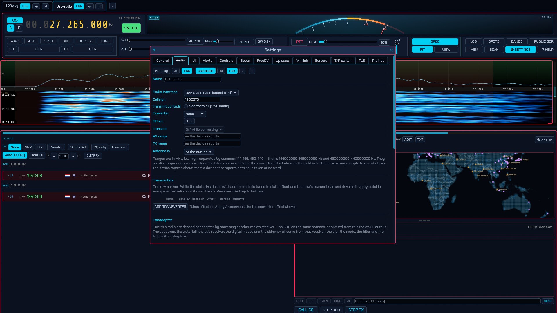
In Settings → Radio, interface USB audio radio (sound card), pick the two devices:
- Receive (radio → PC) — the sound card the radio’s own audio comes in on. Everything on the panadapter and in the decoders arrives here.
- Transmit (PC → radio mic) — the sound card that carries the audio the radio must broadcast. Because the radio keys itself by VOX the moment audio arrives, this device is silent unless the radio is being transmitted through.
That is the whole tab. Every other radio control is absent because the hardware has none: the dial becomes a label rather than a command (the radio tunes itself with its own knobs), and there is no PTT to command — transmit is audio into the radio’s microphone, keyed by VOX. Apply / reconnect reopens the radio with the chosen cards without a restart.
Two things follow from the way it works. The band plan and transmit lockout still apply — sdroxide knows where the dial is because you tuned it here, even though nothing told the radio — so the usual ham-band / 11 m / broadcast rules hold (6.1). And because the only “measurements” come from the audio stream itself, an audio radio has no SWR bridge, no forward-power telemetry and no rig-reported S-meter — the level figures that still work are audio levels, which describe the radio’s own audio rather than what its antenna hears, and the radio’s front panel is where signal strength really lives. It is otherwise a perfectly ordinary radio: every mode, the logbook, the panadapter (a demodulated-audio spectrum), spots and awards all work as they do on any other backend.
15.23 Luiton LT-310SDR — DIY isolated digimode & audio interface (EXPERIMENTAL, at your own risk.)
The Luiton LT-310SDR has no CAT port, so it is driven the way 15.22 describes — through the sound cards — with one difference: the PTT is commanded over a USB-to-serial line, not left to the radio’s VOX. That needs a small, galvanically isolated interface between the PC and the radio.
This is experimental. sdroxide drives it through the T/R switch’s Serial RTS/DTR line rather than a dedicated PTT field; the “keeps receiving if the program dies” behaviour is whatever the serial driver does with RTS when the port closes; and it has not been tested against real hardware here. Build it and use it at your own risk.
The interface
The interface provides galvanic isolation for both audio and PTT control between a PC (running sdroxide, JS8Call, WSJT-X, …) and the Luiton LT-310SDR transceiver.
Components
- 1× FTDI USB-to-TTL adapter: DSD TECH SH-U09C5 (or similar FT232RL module)
- 1× optocoupler: PC817 (DIP-4)
- 1× resistor: 1 kΩ (0.25 W)
- 2× audio isolation transformers: 1:1 600 Ω : 600 Ω (EI14 / Bourns)
- 1× potentiometer: 10 kΩ trimpot (TX audio level adjustment)
- Connectors: 1× RJ12 plug (6P6C), 3× 3.5 mm stereo jacks, perfboard, project box
1. PTT control. Connect the FTDI RTS line through the 1 kΩ resistor to PC817 pin 1 (anode), and FTDI GND to PC817 pin 2 (cathode). Connect PC817 pin 4 (collector) to the PTT pin on the RJ12, and pin 3 (emitter) to the GND pin on the RJ12. Driving RTS HIGH lights the optocoupler’s LED and grounds the radio’s PTT line — no electrical contact between PC and radio.
2. TX audio (PC soundcard out → radio mic in). Connect PC line-out (tip & sleeve) across the primary of the first 1:1 transformer. One secondary pin goes to GND on the RJ12; the other goes through the 10 kΩ potentiometer to the MIC pin on the RJ12. Isolated, and the trimpot stops the PC output overdriving the sensitive mic input.
3. RX audio (radio speaker out → PC soundcard in). Connect the Luiton EXT SPKR 3.5 mm jack (tip & sleeve) across the primary of the second transformer; its secondary goes straight across PC line-in / mic-in (tip & sleeve). Isolated reception for the decoders, and ground-loop mains hum is stripped.
Configuring sdroxide
- Settings → Radio → USB audio radio (sound card) (15.22). Set Receive to the card the radio’s EXT SPKR arrives on, and Transmit to the card feeding the radio’s mic through the trimpot.
- Settings → T/R switch (6.11):
link Serial RTS/DTR line, the FTDI’s port (
/dev/ttyUSB0,COMx), and contact 1 → RTS. Give that contact a role that is not “Ground the SDR antenna” — this is a PTT closure, not an antenna relay; Aux fits, or leave the other contacts at Not used. Key-down asserts RTS and key-up drops it, which is exactly the PTT the interface wants. - Tune on the radio’s own dial. On this backend sdroxide’s dial is a label, so the band plan and the transmit lockout follow what you type here, not the radio (15.22).
The PTT being the T/R switch’s serial line leaves the switch’s other channels free for an antenna relay or an amplifier key line, since each link can carry more than one contact.
Failsafe caveat. sdroxide drops RTS on key-up and closes the port when it exits. Whether the radio returns to receive if the program crashes depends on the serial driver lowering RTS when the port closes — many FTDI drivers do, some do not. If a stuck transmitter must be impossible, wire the optocoupler so a floating RTS is the receive state, and test it.
16. Appendix
Keyboard shortcuts
| Key | Action |
|---|---|
| Left / Right arrow | Tune ±100 Hz (with Shift, ±10 Hz). |
| Up / Down arrow | Tune ±1 kHz. |
| Page Up / Page Down | Tune ±10 kHz. |
| M | Toggle mute. |
| N | Toggle noise blanker. |
| F | Fit the view to the full receiver span. |
| V | Flip the waterfall (scroll upwards). |
| 1 – 9, 0 (numpad) | Transmit voice-keyer slots 1–10 (nothing if the slot is empty). |
| − (numpad) | Stop a voice-keyer message. |
| Space (CW, with KEY on) | The straight key: carrier while held, and re-bindable as CW straight key in Settings → Controls (2.14). |
| Ctrl+W | Open Settings on the UI page, where saved window arrangements (Workspaces) are listed (6.4). |
| F1 | Open this manual (works even while typing). |
Shortcuts are ignored while typing in a text field.
While this manual is open it takes the scrolling keys for itself, so reading it never tunes the radio at the same time: Up / Down scroll a few lines, Page Up / Page Down scroll a screen, Home / End jump to the ends, and Left / Right step to the previous / next section in the CONTENTS outline. Esc or F1 closes it and the keys go back to tuning.
It opens filling the window, and you can move and resize it from there like any other panel.
Finding something. The bar across the top searches the whole manual as you type. Every occurrence is highlighted where it stands, the one you are on in yellow and the rest in cyan, and the view follows it:
| Key / button | What it does |
|---|---|
| Ctrl+F | Puts the caret in the find field. |
| ▶ or Enter or F3 | Next match (wraps round at the end). |
| ◀ or Shift+Enter or Shift+F3 | Previous match. |
| ✕ or Esc | Clears the search. A second Esc closes the manual. |
The tally beside the buttons reads 3 / 17 — which match you are on, out of how
many there are. In the CONTENTS outline every chapter and subsection holding the
term turns yellow with a count beside it, so a term that only appears in one
chapter out of eleven is visible before you scroll anywhere: search for WSPR
and the outline tells you where it is discussed and how much is said about it.
The search is case-insensitive, so wspr and WSPR find the same things.
These are the defaults. Every one of them can be rebound — and PTT, band changes, filter width and much else bound to keys, mouse buttons or a MIDI controller — on the Controls tab; see 6.4. F1 is the exception: it always opens the manual, so it is not rebindable.
The spoken-announcement actions (6.3) ship with no default keys, since any choice would take a key somebody is already using. Bind them under Speech on the Controls tab:
| Action | What it does |
|---|---|
| Speak status | Reads the whole radio out: band, frequency, mode, VFO, split, and the SWR while keyed. |
| Repeat last announcement | Says the last one again — for the word that a burst of noise landed on. |
| Stop speaking | Stops mid-sentence and drops whatever is queued. |
| Announcements on/off | The master switch, confirmed out loud when switching on. |
Modes
| Mode | Description |
|---|---|
| LSB / USB | Lower / upper sideband voice. |
| CW | Morse (continuous wave). Decoded on a waterfall cursor, with type-ahead keyboard sending — see 2.14. |
| AM | Amplitude modulation. |
| SAM | Synchronous AM. Its ECSS-U/ECSS-L filter presets keep one sideband and reject the other — the medium-wave DX trick for ducking an adjacent channel. |
| C-QUAM | C-QUAM, Motorola’s AM stereo for the medium wave: AM carrying the sum and the stereo difference as carrier phase, with a 25 Hz pilot for the stereo lamp and the mono blend. Receive only. See cquam-design.md. |
| NFM / WFM | Narrow / wide FM. WFM decodes broadcast stereo and RDS/RBDS automatically. |
| DIGU / DIGL | Data over USB / LSB (general digital). |
| DSB | Double sideband. |
| ISB | Independent sideband: two different signals on one carrier, one on each sideband — a broadcaster’s two language services, or voice on one side and a teleprinter on the other. The lower sideband goes to your left ear and the upper to your right, so both can be listened to at once (or one recorded while the other is read). Receive only. |
| DRM | Digital Radio Mondiale — digital shortwave broadcasting. Receive only; decodes the programme audio, the station label and its scrolling text. See 2.19. |
| SPEC | Spectrum only (no demodulation). |
| FT8 / FT4 | Automatic digital modes with decoding, QSO sequencing, and logging. |
| JS8 | JS8 — conversational messaging on FT8’s waveform. Four speeds (Normal 15 s / Fast 10 s / Turbo 6 s / Slow 30 s); directed queries, heartbeats and multi-frame free text. |
| WSPR | Weak Signal Propagation Reporter — a two-minute beacon carrying a callsign, grid and power. Not a QSO mode: it measures paths, uploads them to WSPRnet, and feeds the propagation heat map. See 3.11. |
| PI4 | “Next Generation Beacon” — a one-minute four-tone FSK beacon carrying a callsign. Receive only. Not a QSO mode: it measures paths, and carries no grid to feed the propagation heat map with. See 3.20. |
| PSK | PSK31 keyboard mode (BPSK31 / varicode). |
| RTTY | RTTY keyboard mode (Baudot; selectable shift and baud), on a sideband. |
| RTTY-FM | The same modem on an FM carrier, the way a club bulletin is still sent on VHF. |
| NAVTEX | The maritime safety broadcast on 518, 490 and 4209.5 kHz: navigational and meteorological warnings, search-and-rescue bulletins and ice reports, framed into messages. Receive only. |
| DSC | Digital Selective Calling — the marine distress and calling system on VHF channel 70 and the MF/HF distress channels: 1200-baud FFSK carrying distress alerts (MMSI, nature, position, time) and routine calls. Receive only. See 3.21. |
| JT65 / JT9 | The classic WSJT weak-signal modes — 65-FSK (JT65) and 9-FSK (JT9), both in a 60-second slot, carrying <to> <from> <grid\|report>. Receive only in this build (no QSO sequencer). See 3.22. |
| FST4 | The slow weak-signal mode for EME, troposcatter and LF/MF: 160-symbol GFSK in a 15/30/60/120/300-second T/R period, carrying the same 77-bit message as FT8/JT65. Receive only in this build. See 3.23. |
| MSK144 | Meteor scatter on 6 m and 2 m: continuous-phase binary MSK at 2000 baud in a 15-second period, carrying the same 77-bit message as FT8. The decoder hunts the period for meteor-trail bursts. Receive only in this build. See 3.24. |
| Q65 | The modern WSJT weak-signal mode for EME, ionoscatter, rainscatter and troposcatter: 65-tone FSK in a 15/30/60/120/300-second T/R period, with a tone-spacing letter A–E for Doppler spread. Carries the same 77-bit message as FT8. Receive only in this build. See 3.25. |
| UVPACKET | A packet protocol for private amateur VHF/UHF groups: a short π/4-DQPSK burst carrying an application byte pipe (app type, sequence, 1–32 payload blocks) rather than a WSJT message. The sub-mode is detected from the preamble. Receive only in this build. See 3.26. |
| JTTY | Experimental. The WSJT-X 3.2 asynchronous RTTY-like text mode: no T/R slots, ~1.888-second frames of 4-GFSK about 125 Hz wide carrying free text or typed contest atoms behind a tail-biting convolutional code. Sends a message once. See 3.28. |
| FSK441 | The original meteor-scatter mode on 6 m and 2 m: 4-FSK at 441 baud carrying free text and the R26/R27/RRR/73 single-tone shorthand, in a 15/30-second period. The decoder hunts the period for meteor-trail pings; transmit repeats the message for the length of the over. See 3.27. |
| OLIVIA | Robust MFSK keyboard mode (selectable tones/bandwidth). |
| THOR | DominoEX-family IFK keyboard mode with FEC (THOR4…THOR32). |
| FSQ | Fast Simple QSO — 33-tone IFK with directed (FSQCALL) messaging and images. |
| HELL | Hellschreiber — facsimile “dot” mode read by eye, not decoded (Feld Hell, Slow, X5, X9, FSK Hell 245/105, Hell 80). |
| SSTV | Slow-scan TV image mode (Scottie, Martin, Robot), on a sideband — LSB on 160/80/40 m, USB above. |
| SSTV-FM | The same picture on an FM carrier, the way slow-scan is sent on VHF and UHF. |
| RIFP | Radio Image Framing Protocol (draft-dulaunoy-rifp-00): packetised images over continuous-phase FSK. Centred on the dial, ~25 kHz wide — 70 cm, 2 m/6 m all-modes, or 10 m FM. |
| RFPAINT | RF Paint — transmit-only spectrum painting of text and images onto the waterfall. |
| RADE | FreeDV RADE V1 — digital voice: a neural codec (Radio Autoencoder) over an OFDM waveform about 900 Hz wide, decoded speech in place of what the receiver hears. On a sideband, and which one follows the band the way phone does — LSB on 160, 80 and 40 m, USB on 60 m, 30 m and above. |
| PACKET / PACKET-HF | AX.25 packet radio: 1200 baud Bell 202 or 9600 baud G3RUH on VHF/UHF FM, 300 baud AFSK on HF sideband. Carries Winlink sessions and offers the modem as a KISS TNC. See 11. |
| APRS | Automatic Packet Reporting System — 1200 baud AX.25 on the region’s shared channel, with a live map of every station heard, its own symbol per station, and messages you can send and answer. See 3.12. |
| ADS-B | Aircraft surveillance on 1090 MHz: a target list and a radar picture with history dots, speed vectors and data blocks. Receive only, and needs a receiver streaming at least 2 Msps. See 3.13. |
| VDL2 | The VHF datalink aircraft exchange ACARS over, on fourteen channels between 136.650 and 136.975 MHz at once: a message log and the stations sending them. Receive only. See 3.15. |
| AIS | Ship reporting on the two channels either side of 162.000 MHz at once: a vessel list and a marine chart with hulls drawn to their heading, time-based trails and speed vectors. Receive only. See 3.16. |
| ACARS | Airline datalink on VHF airband, decoded off the AM carrier: aircraft registrations, labels and message text, every message block-checked. Receive only. See 3.18. |
| HFDL | The shortwave aircraft datalink (ARINC 635): ground stations across 2.8–22 MHz talking to aircraft over the ocean, with a decode log and an aircraft map drawn from the positions the aircraft downlink. Receive only, on an HF receiver. See 3.19. |
| ATCHAT | AtCHAT NET — a 2.7 kHz COFDM multi-station keyboard and file mode: dynamic master election, a shared roster, common and directed chat, and block-CRC-ARQ file/image transfer. See 3.17. |
Bands
160M, 80M, 60M, 40M, 30M, 20M, 17M, 15M, 12M, 10M, 6M,
4M (Region 1 only), 2M, 1.25M (Region 2 only), 70CM, 33CM (Region 2
only), 23CM, 13CM, 9CM, 6CM — read as 5CM outside Region 1 — and
ALL (general coverage, formerly GEN). Bands your
device cannot receive are disabled in the selector; bands your region does not
have are not offered.
Waterfall colour schemes
Classic (PowerSDR-style), Viridis, Gray, Icom (Icom-style palette,
peaking at red with no white blow-out), Neon, Synthwave, Matrix, Tron,
Amber (one warm phosphor family, to wear with the Amber Phosphor UI
theme), Rainbow (the full spectrum in order, to wear with the Rainbow
UI theme) and Blue — the traditional blue waterfall SDR# has used since the
beginning and SDR++ inherited: a navy floor rather than a black one, so the
noise keeps its texture, and a top half that runs white, yellow, orange and two
shades of red where the other ramps have already saturated. Chosen on the UI
tab of the Settings window (6.3).
17. Addendum: a headless station on a Raspberry Pi Zero 2 W
A small, cheap board with a USB dongle makes a good network listening node: the receiver and the decoding run on the board, and your laptop, tablet or phone drives it through a browser. This is the “Pi at the antenna” arrangement §8 and §9 describe, sized for a Raspberry Pi Zero 2 W.
The board is 64-bit (armv8), so it runs the linux-aarch64-compat build
made for Raspberry Pi OS Bookworm — no compiling. Run it as a server and use
a browser for the drawing: that split is what makes a four-core, 512 MB board
useful, because the graphical interface is the part it cannot carry.
Three things decide whether it is pleasant or painful:
- Keep the sample rate low — 1.024 Msps or less on Settings → Radio. The narrow modes need a fraction of an RTL-SDR’s 2.4 Msps default, and the low rate is what keeps the board cool and ahead of the DSP.
- Stay off the wideband lanes — ADS-B, VDL2, AIS and DAB need sustained megahertz of throughput and memory the board does not have. The narrow decoders (FT8/FT4/FT2, WSPR, JS8, PSK/RTTY, NAVTEX, DSC, ACARS), the broadcast listening and the scheduled recordings are the workload it does well.
- Power the dongle through a powered USB hub. The Zero 2 W has one USB OTG port and a regulator that cannot reliably feed an SDR; brown-outs look like “radio not found” or dropped samples, and they are the commonest reason a Pi-and-dongle setup seems not to work.
The full walkthrough — imaging the card, installing the aarch64-compat build,
the udev rules, the first-run setup, the systemd service and the troubleshooting
in one place — is the Pi Zero 2 W setup guide, in the same four languages as
the quick-starts:
For a graphical sdroxide on the Pi itself, or for the wideband decoders, step up to a Pi 4 (2 GB+) or Pi 5 — see the README’s Raspberry Pi note about Mesa’s V3DV Vulkan driver and the OpenGL fallback.