sdroxide-brown
QO-100 quick-start (sdroxide + ADALM-Pluto)
A task-oriented walkthrough for getting an ADALM-Pluto + Ku-band LNB
station onto the QO-100 (Es’hail-2) geostationary transponder with sdroxide. It
covers the one-time station setup, locking onto the bird, and the QO-100
beacon-sync tab. For the reference detail behind each control, see
USER_MANUAL.md §2.22 (QO-100 beacon plugin) and §6.2.7
(PlutoSDR).
The 10 GHz downlink comes down through the LNB; the 2.4 GHz uplink leaves the Pluto directly.
What you need
- ADALM-Pluto (or a LibreSDR / ANTSDR-class AD936x board).
- A universal Ku-band LNB with a 9750 MHz local oscillator — the usual QO-100 choice.
- A dish, the coax from the LNB, and a 2.4 GHz uplink antenna.
- sdroxide installed. The Pluto driver is built in; there is nothing else to install.
The frequency chain
downlink   10489.750 MHz --> LNB (LO 9750 MHz) --> 739.750 MHz --> Pluto
uplink      2400.xxx MHz <-- Pluto (direct, not converted)
Bold names such as Converter are buttons and fields exactly as they appear on
screen. Settings > Radio is a menu path; 192.168.2.1 is a value you type.
Part A — Settings
Done once and saved. Everything is in the Settings window, on the General and Radio tabs.
1. Start sdroxide
Open the program. The main window has the control bar across the top and the panadapter and waterfall below it.
2. Open the settings
Press SETTINGS on the top control bar.

3. Callsign and locator
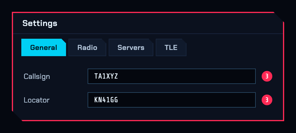
On the General tab, enter your callsign in Callsign and your Maidenhead
grid (e.g. KN41GG) in Locator. The satellite lock and the world map use
this locator — LOCK ON will not work without it.
4. Radio tab — device: PlutoSDR
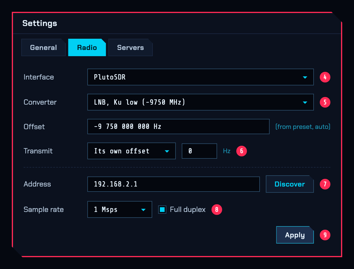
Switch to the Radio tab and pick PlutoSDR in the interface selector. A Pluto is a network device even on a USB cable: plugging it in creates a network adapter, not a serial port. The next five fields are on this same tab:
5. Converter: LNB, Ku low (-9750 MHz)
In the Converter dropdown, pick the LNB, Ku low (-9750 MHz) preset —
because our LNBs have a 9750 MHz local oscillator. This fills in the
-9 750 000 000 Hz offset below automatically, so the 10489.750 MHz beacon lands
near the right place on the dial.
6. Transmit row: Its own offset = 0
In the Transmit row next to the converter offset, choose Its own offset
and type 0 into the Hz box beside it.
There is no need to enter a TX figure such as 8085 MHz the way we used to. This
0 means “the downlink comes through the LNB, but the 2.4 GHz uplink leaves the
radio directly — the transmit side is not converted”. If you later find your TX
frequency is off, correct it from this box (in Hz, same sign rule as the receive
offset).
7. Pluto address
In the connection section below, type the Pluto’s IP into Address, or let
Discover find it. Over USB, 192.168.2.1 is enough. On a LAN, use the
Pluto’s address on that network. ip:192.168.2.1 is also accepted; an address
starting with usb: is refused, because this backend reaches the radio over the
network the USB cable already provides.
8. Sample rate and Full duplex
Set Sample rate to 1 Msps and tick Full duplex below it, so you keep
hearing your own downlink while transmitting.
Note. Full duplex only works over real Ethernet — a Pluto or LibreSDR behind a gigabit adapter. Over USB the station is half-duplex and you will not hear your own downlink during an over. Also, a stock Pluto cannot go below about 2.084 Msps; a lower value is rounded up and the connection message says so.
9. Apply and close
Press Apply at the bottom and close the Settings window. Settings take effect on Apply / reconnect.
Part B — Locking onto the satellite
Done each time you work the bird.
10. Open the SAT window
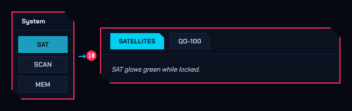
Press SAT in the System box. The button glows green while a lock is running; the correction keeps being applied even with the window closed.
11. Pick QO-100
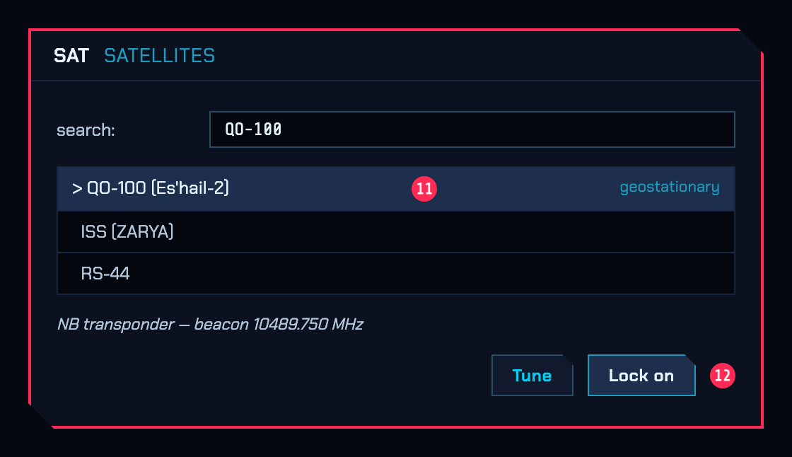
On the SATELLITES tab, type QO-100 into the search box and pick it from the
list. Its published links (narrowband transponder, beacon) appear below.
12. LOCK ON
Press LOCK ON at the bottom. QO-100 is geostationary, so it needs no Doppler correction; the transponder mapping derives the 2.4 GHz uplink from wherever you set the downlink dial.
Part C — Beacon sync
Optional but recommended. If your LNB is not very stable, the QO-100 beacon-sync plugin (contributed by the ATÖLYE group) measures where the 10489.750 MHz narrowband beacon really is, corrects the converter/LNB offset so the dial and the signal agree, and keeps correcting it as the LNB warms up and drifts.
13. Switch to the QO-100 tab
It is the second tab of the SAT window.
Prerequisite. The plugin corrects a residual error of a few kHz to tens of kHz — it does not guess from scratch. The
Settings > Radioconverter offset has to be roughly right first (step 5), so the beacon lands somewhere near 10489.750 MHz.
14. See the beacon in the strip
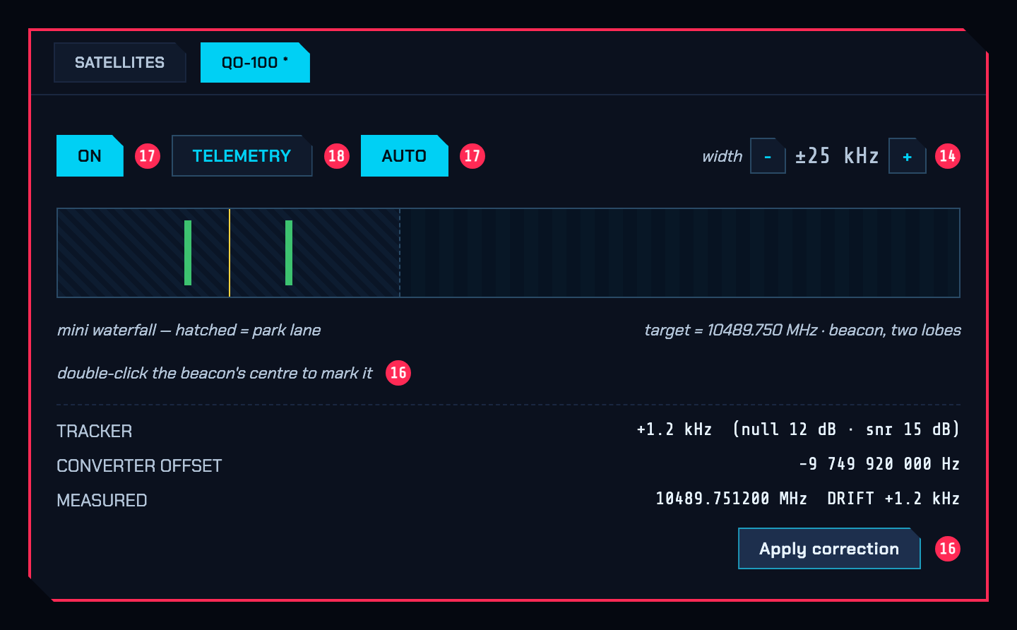
If the beacon is not visible as a band / two symmetric lobes, step width up with + (±5 kHz steps, up to ±50 kHz). Widen only until the two lobes and the null between them are clear, then bring it back toward ±5 kHz.
15. Still nothing: nudge 9750 by hand
Nudge the 9750 MHz converter offset in Settings > Radio to an approximate value
in the right direction and press Apply; repeat until the beacon is inside the
strip. The plugin takes it from there.
16. Simple (one-shot) correction
Double-click the middle of the beacon in the strip. That plants a “the beacon is here” mark (the two lobes, centred on the null). Then press APPLY CORRECTION at the bottom. The receiver reopens on the corrected offset and the beacon jumps toward the centre. Two passes — one wide (coarse), one narrow (fine) — get it within a few hundred Hz.
17. Automatic, continuous correction
Press ON (the spectral tracker starts — it only measures, it changes nothing), then AUTO (the loop closes: every clean, steady measurement is applied as a slow, rate-limited nudge to the offset).
AUTO then corrects LNB drift in the background. A single noisy reading never yanks the receiver; it takes a run of agreeing measurements to move the offset. No correction is made while you are transmitting — each one reopens the receiver, which would cut off your over — so a held-back correction goes out as soon as the over ends. AUTO also watches its own work and switches itself off if the offset it writes does not move the beacon, or if it has gone further than any LNB could plausibly be out by, with a notice saying which.
18. Telemetry (optional)
Press TELEMETRY to run the AO-40 frame decoders; the beacon’s own status text appears when it locks. Not needed for calibration — it is an independent check.
19. Leave it running in the background
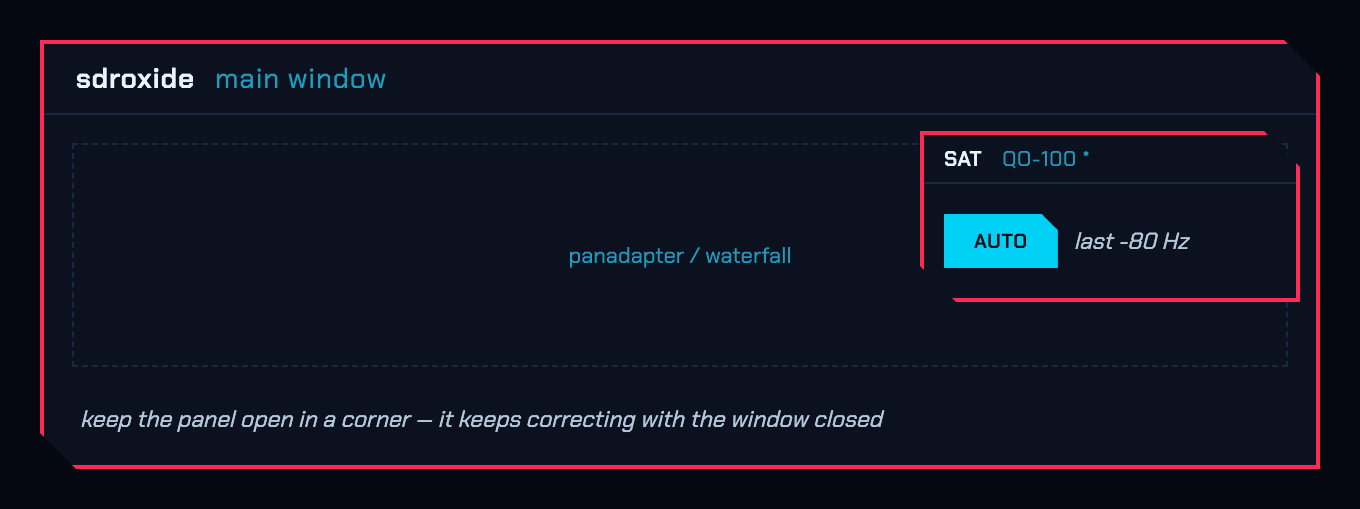
When you are done, minimise this window and keep it in a corner of the screen (closing it is fine too). The LNB correction keeps going with the window closed; the SAT chip stays lit and the QO-100 tab keeps its dot.
Good QSOs, and 73.